1 minute read
Upper Front Gear Group (7N4871


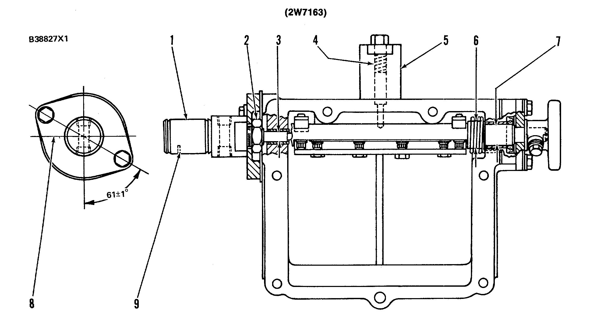
AIR INTAKE SHUTOFF
(1) Hydraulic shutoff cylinder. Make an alignment of cylinder port and vent hole (9) in a vertical downward position at assembly.
Advertisement
(2) Torque for nut that holds cylinder (1) to the flange............................45 ±7 N•m (33 ±5 lb. ft.)
(3) Diameter of cylinder rod .....................................7.920 ± 0.013 mm (.3118 ± .0005 in.)
Bore in bushing after assembly.....................................7.996 ± 0.044 mm (.3148 ± .0017 in.)
Bore in housing for bushing .....................................9.525 ± 0.013 mm (.3750 ±.0005 in.) Install bushing with split along centerline (8) toward front or rear.
(4) 2V244 Spring for shutoff actuator pin:
Length under test force................29.2 mm (1.15 in.) Test force.......8.9 ± 0.7 N (2.00 ±.16 lb.) Free length after test....................54.6 mm (2.15 in.) Outside diameter .....................9.04 mm (.356 in.)
(5) Torque for carrier (put 2P2506 Thread Lubricant on the threads).............................70 ± 10 N•m (50 ± 7 lb. ft.)
(6) Bore in spring bushing..................19.30 ± 0.25 mm (.760 ±.010 in.)
Diameter of shaft .....................18.97 ±0.02 mm (.747± .001 in.)
(7) Diameter of shaft .....................18.97 ±0.02 mm (.747 ± .001 in.)
Bore in two shaft bushings (after assembly) .....................19.050 ±0.044 mm (.7500 + .0017 in.)
Bore in housing for bushings........22.205 ±0.013 mm (.8742 0005 in.)