38 minute read
Appendix


A. TIMING ADVANCE FAILURES
Timing advance failures have occurred on 2EK and 4CK engines. The January 1995 TEN article (included) summarizes nine improvements that should be checked before releasing a truck with a failed timing advance unit.
Recently, the fuel camshaft bearings have been shown to be a contributor to timing advance failures. These bearings should be replaced as part of an OPT or normal overhaul. They should also be checked for wear, on any engine that has high mileage and multiple timing advance failures.
In addition to the nine improvements, there are two Service Letters that should be mentioned. Service Letter PS8200 (Increase Oil Sump to 40 Quarts) and Service Letter PI3005 (Install Derate Software to Limit Contingent Damage After Timing Advance Failure).
These Service Letters are included in this chapter as well as Truck Engine News articles that relate to this subject.
Truck Engine News
Media Number - SEBD6662-00 Publication Date - 1995/01/01
Electronic Timing Advance Improvements
1272, 1253, 1264
3406B (8TC, 2EK), 3406C (4CK) Truck Engines Numerous improvements have been made to the electronic timing advance components on these truck engines. The Steps that follow provide a way to check the electronic timing advance components to determine if the latest components and improvements are incorporated. Use the chart to determine which Steps apply to your engine.
Engine S/N Range Applicable Step(s) 8TC1 - Up 1 - 4, 6 - 10 8TC1 - 13234 5, 10 2EK1 - Up 1 - 4, 7 - 10 2EK1 - 01823 6, 10 4CK1 - Up 3, 7, 9, 10 4CK1 - 2537 1, 10 4CK1 - 6001 2, 10 4CK1 - 11473 4, 10 4CK1 - 15840 9, 10
NOTE: * Steps 1 through 3 can be performed without removing the cover.
* Steps 4 through 7 require removing the cover.
* Step 8 requires the disassembling the timing advance.
* Step 9 requires removing the governor if the gasket is leaking.
* Step 10 should NOT be done on the 2EK/4CK Rear Sump configurations or Brakesaver™ equipped engines.
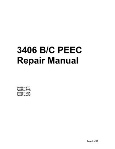
1. Check solenoid (BTM) arm. See Illustration 1, Item 1. * Check arm to shaft joint for damage.
* Check the solenoid part number. The former 9X-6770 Solenoid has been replaced by the new 105-2939 Solenoid. The new solenoid has a stronger shaft. This change is effective with S/N 4CK2537.
2. Check control group (timing sensor) for a loose tip. See Illustration 1, Item 2. * Check for loose tip.
* Put 9S-3263 Thread Lock of the threads of the 9X-9555 Control Group (timing sensor) before it is installed. This change is effective with S/N 4CK6001.
* The 118-7204 Sensor Tip Kit is available for repairing or replacing the sensor tip.
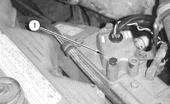
3. Check to be sure the bell crank is in the correct position. See Illustrations 1 and 2, Item 3 and Illustration 3, Items 5 and 6. * Check the thrust bearing face and the front of the 2W-3635 Sleeve for wear caused by the bell crank being out of position with respect to the thrust bearing.
4. Check bell crank assembly to be sure pin (4) is correctly installed. See Illustrations 1 and 2, Items 3 and 4. * Check the faces of the bell crank to be sure that no excessive wear has occurred.
* Check round area of the bell crank to be sure the spring is not causing galling of the bell crank on the pivot pin.
* The 2W-3623 Bell crank Assembly pin depth is correct effective with S/N 4CK11473.
* Bell crank endplay should be .13 to .64 mm (.005 to .025 in).
5. Check spool in fuel pump and governor drive group. See Illustration 3, Item 7.
* Check spool for damage and part number.
* Replace former 4W-2750 or 7E-5564 Spool with new 4P-3384 Spool. The new spool is effective with S/N 8TC13234.
6. Check eight bolts (8) in fuel pump and governor drive group. See Illustration 3, Item 8. * Check to be sure 6J-2819 Bolts (8) are used.
* Tighten the 6J-2819 Bolts to a torque of 16 N·m (12.0 lb ft). The new longer bolts and higher tightening torque are effective with S/N 2EK1823.
7. Check to be sure the former 3P-3547 Retaining Ring has been replaced by the new 108-4511 Clamp Assembly. See Illustration 3, Item 9.
8. Check to be sure the plug is in position in the carrier assembly. See Illustration 3, Item 10. (New threaded plug used with 101-1944 Carrier Assembly shown.) * New 101-1944 Carrier Assembly with threaded plug effective with S/N 4CK4699.
* Do NOT use former 0T0200 Cup Plug.
9. Check for oil leak between governor and fuel injection pump housing. See Illustration 4, Item X. * Oil leak can be internal or external.
* Oil leaking past 4W-2491 Gasket.
* New tightening specification for 8S-4710 Bolt (11) is 16 ± 4 N·m (12 ± 3 lb ft) and is effective with S/N 4CK15840.
Illustration 1. Timing Control Group components. Solenoid (1). Control Group (2). Bell crank Assembly (3). Pin (4).
Illustration 2. (View A-A) Timing Control Group components. Bell crank Assembly (3). Pin (4).
Illustration 3. Governor And Fuel Pump Drive Group components. 2W-3635 Sleeve Assembly (5). Thrust bearing (6). 4P-3384 Spool (7). 6J-2819 Bolts (8). 108-4511 Clamp Assembly (9). 101-1942 Plug in 1011944 Carrier Assembly (10).
Illustration 4. Governor And Fuel Injection Pump Group. 8S-4710 Bolt (11)
STEP 10
Truck Engine News
Media Number - SEBD6660-00 Publication Date - 1994/11/01
Engine Oil Capacity Change
1326, 7542
3406 (92U), 3406B (7FB, 8TC, 4MG, 5YG, 3ZJ, 5KJ), 3406C (3ZJ, 5KJ, 8PN), 3406E (5EK) Truck Engines Except 3406B (2EK) PEEC And 3406C (4CK) Electronic Engines Equipped With Front Sump Oil Pan The approved oil capacity for the above truck engines has been increased to 40 quarts or 10 gallons. Formerly the capacity was 36 quarts or 9 gallons. The new 120-8972 Oil Level Gauge (dipstick) is available to retrofit MOST existing engines to measure the increased capacity. The new dipstick will fit both front and rear sump non-Brake Saver applications. The new dipstick is NOT a full range dipstick. There are NO oil level marks or crosshatch on the new dipstick. Since each application is different, the location of the "FULL" and "ADD" marks will vary. Use the "120-8972 Oil Level Gauge Calibration Procedure" to establish the "FULL" and "ADD" add marks on the new dipstick. The new calibration procedure is for the 40 quart "FULL" mark with a 34 quart "ADD" mark. The new calibration procedure was created to minimize errors related to drain back time by compensating for oil that is hung up in the cylinder head. The new procedure also takes into account the oil that is not measurable in the deep sump because it is trapped in the shallow sump. The new oil capacity, dipstick, and dipstick calibration procedure can help alleviate some oil consumption complaints by increasing the effective operating range by two quarts and by improving the dipstick accuracy. The perception of excessive oil consumption can be changed by expanding the size of the operating range. The expanded operating range will help decrease the number of oil additions into an otherwise healthy engine during the oil change period. The chance of overfilling will also be reduced. Some complaints of excessive oil consumption can be directly related to overfilling caused by misinterpreting the full range dipsticks.
This procedure will calibrate the 120-8972 Dipstick to accurately register a 40 quart FULL capacity and a 34 quart ADD capacity on 3406, 3406B, 3406C, and 3406E Truck Engines. NOTE: This procedure should NOT be used on 3406B PEEC and 3406C Electronic Engines equipped with a front sump oil pan.
1. Drain a hot engine for 20 minutes. Remove BOTH shallow sump and deep sump drain plugs.
2. Remove the oil filter.
3. Install the drain plugs removed in Step 1.
4. Install a new DRY oil filter.
5. Add 28 quarts (7 gallons) of CF4 oil to the engine at locations 1, 2, or 3. ONLY THESE FILL LOCATIONS SHOULD BE USED WITH THIS PROCEDURE. (See the illustration.)
Locations to add oil for dipstick calibration. Location 3 is one of three plugs in unused oil level gauge locations.
6. Install the new 120-8972 Dipstick into the guide tube. Then remove the dipstick and NOTE the oil level on the dipstick.
7. Mark this level on the new dipstick as "ADD" with an engraving pen or other comparable tool.
8. Add 6 quarts (1.5 gallons) of oil to the engine at locations 1, 2, or 3. ONLY THESE FILL LOCATIONS SHOULD BE USED WITH THIS PROCEDURE. (See the illustration.)
9. Install the new dipstick into the guide tube. Then remove the dipstick and NOTE the oil level on the dipstick.
10. Mark this level on the new dipstick as "FULL" with an engraving pen or other comparable tool.
11. Add 6 quarts (1.5 gallons) of oil to the engine for a total fill quantity of 40 quarts.
Systems Operation
3406C (PEEC III) Truck Engines
Media Number - SENR5508-02 Publication Date - 2001/10/01
Governor Servo
Date Updated - 2001/10/11
Illustration 14 Rack Movement Toward Full Fuel (A) Oil inlet (B) Oil outlet (C) Oil passage (D) Oil passage (E) Pressure oil (F) Drain oil (1) Piston (2) Cylinder (3) Sleeve (4) Valve g00536051
When the rack solenoid (BTM) is energized, the rack solenoid moves valve (4) to the left. The valve opens oil outlet (B) and the valve closes oil passage (D). Pressure oil from oil inlet (A) pushes piston (1) and fuel rack (5) to the left. Oil that is behind the piston goes through oil passage (C) and along valve (4) and out oil outlet (B).
Illustration 15 No Rack Movement (Constant Engine Speed) (A) Oil inlet (B) Oil outlet (C) Oil passage (D) Oil passage (E) Pressure oil (F) Drain oil (G) Blocked oil (1) Piston (2) Cylinder (3) Sleeve (4) Valve (5) Fuel rack g00536053
When the desired engine speed is reached, the Rack Solenoid (BTM) holds valve (4) in a fixed position. Piston (1) moves to the left until both oil outlet (B) and oil passage (D) are blocked by valve (4). Oil is trapped in the chamber behind piston (1). This creates a hydraulic lock which stops the piston and fuel rack movement.
Illustration 16 Movement Of Rack Toward The Fuel Off Position (A) Oil inlet g00536054
(B) Oil outlet (C) Oil passage (D) Oil passage (E) Movement of rack toward the fuel off position (F) Pressure oil (G) Drain oil (1) Piston (2) Cylinder (3) Sleeve (4) Valve (5) Fuel rack
When the Rack Solenoid (BTM) is de-energized, spring force in the solenoid moves valve (4) to the right. The valve closes oil outlet (B) and opens oil passage (D). Pressure oil from oil inlet (A) is now on both sides of piston (1). The left side area of the piston is greater than the right side area of the piston. The force of the oil is also greater on the left side of the piston. This moves the piston and fuel rack (5) to the right.
Timing Advance Unit
Illustration 17 Front View of Timing Advance Unit (1) Timing solenoid (2) Timing position sensor (3) Bell crank g00536055
Illustration 18 Timing Advance Unit Before Any The Timing Advance (A) Pressure oil (B) Blocked oil (C) Drain oil (1) Timing solenoid (4) Sleeve (5) Valve spool (6) Ring (7) Gear (8) Carrier (9) Fuel injection pump camshaft (10) Body assembly (11) Bolt (12) Ring g00536056
The timing advance unit connects the drive end of the fuel injection pump camshaft with the timing gears in the front of the engine. The unit uses engine oil pressure to change the fuel injection timing. An electronically actuated timing solenoid (BTM) controls a double acting hydraulic servo. The double acting hydraulic servo directs engine oil that is under pressure to either side of the drive carrier. The side determines if the timing will be advanced or if the timing will be retarded. The total timing advance range is 25 crankshaft degrees. Timing is controlled by the PEEC III system as a function of the following conditions: engine rpm, load demand (rack position), boost pressure, engine acceleration and throttle position. A timing position sensor is used for accurate feedback control of the timing
advance through the ECM and the timing solenoid (BTM). Timing position sensor (2) is located on top of the timing advance actuator housing. Bell crank (3) is used to transfer linear motion of the timing advance unit to the end of Timing Position Sensor (2). Bell crank (3) is in contact with a thrust bearing. The thrust bearing is fastened to the timing advance body assembly (10) and the thrust bearing follows the movement of the timing advance body assembly (10). The timing solenoid (BTM) (1) is installed toward the inside of the engine into the timing advance actuator housing. The timing solenoid (BTM) is spring loaded toward the retarded position. The timing solenoid (BTM) must receive a positive voltage from the ECM in order to move the servo valve spool that changes the fuel injection timing. The lever of Timing Solenoid (BTM) (1) is connected to servo valve spool (5) through sleeve (4). The timing advance unit is connected to the fuel injection pump camshaft. Bolts (11) pull rings (6) and (12) together in order to hold gear (7). Carrier (8) has two helical splines. The outer splines are in contact with the helical splines of ring (6) and the inner splines are in contact with the helical splines on fuel injection pump camshaft (9). When the engine is started, gear (7) drives fuel injection pump camshaft (9) through ring (6) and carrier (8).
Advance Timing
Illustration 19 Oil Pressure Locations Toward Maximum Timing Advance (A) Pressure oil (B) Drain oil (1) Timing solenoid (4) Sleeve (5) Valve spool (6) Ring (7) Gear (8) Carrier (9) Fuel injection pump camshaft g00536057
(10) Body assembly (11) Bolt (12) Ring
As the engine begins to run, the ECM sends current to the timing solenoid (BTM) which moves valve spool (4) to the left in the above illustration. At this point, the valve spool (4) closes off the oil drain passage in the body assembly (10). Engine lubrication oil flows through the fuel injection pump housing and through a passage in the fuel injection pump camshaft (9) into the body assembly (10) and the oil is stopped by the valve spool (4). Oil pressure pushes the body assembly (10) and the carrier (8) to the left. As carrier (8) is forced to the left by oil pressure, the carrier slides between the helical splines on ring (6) and the helical splines on the fuel injection pump camshaft (9). The helical splines that are on the carrier and the ring cause the camshaft to turn in relation to gear (7). This outward motion of the body assembly (10) causes the fuel injection timing to be advanced.
Retarded Timing
Illustration 20 Retarded Timing (A) Pressure oil (B) Drain oil (1) Timing solenoid (4) Sleeve (5) Valve spool (6) Ring (7) Gear (8) Carrier (9) Fuel injection pump camshaft (10) Body assembly (11) Bolt (12) Ring g00536058
When the ECM senses a need for the engine timing to be retarded, the voltage to the timing solenoid (BTM) is reduced. Spring pressure in the timing solenoid (BTM) moves valve spool (4) to the right in the above illustration. This blocks the engine lubrication oil from the oil drain passage on the outer end of body assembly (10). The oil flows from the fuel injection pump camshaft (9), through the body assembly (10) and around the valve spool (4). The oil pressure builds up and the oil pressure moves the body assembly (10) and the carrier (8) to the right. This action causes fuel injection pump camshaft (9) to turn in relation to gear (7) and fuel injection timing is retarded.
Oil Flow for Fuel Injection Pump, Rack Actuator, and Automatic Timing Advance
Illustration 21 Fuel Injection Pump and Rack Actuator Oil Flow (A) Pressure Oil (B) Drain Oil (1) Fuel injection pump housing (2) Rack actuator housing (3) Oil passage for the cylinder block (4) Oil drain passage to the cylinder block (5) Transducer module g00536059
Lubrication oil under pressure is supplied to the fuel injection pump housing from the left side of the cylinder block through passage (4). At this point, part of the oil flows into a
main oil passage in fuel injection pump housing (2) in order to lubricate the three fuel injection pump camshaft bearings. At the camshaft bearing that is next to the rack actuator housing, oil flows between the bearing and the camshaft in order to lubricate the thrust bearing for the camshaft retainer. Oil flows at the camshaft bearing on the drive end of fuel injection pump housing (2) into drilled passages in the camshaft. The oil in the camshaft supplies oil to the timing advance unit. Oil drains from the camshaft bearings into the fuel injection pump housing. An oil drain hole keeps the level of the oil in the housing even with the center of the camshaft. Oil drains from the housing, through drain port (5) and back to the engine block. From passage (4), part of the oil is directed back to the passages that are formed between the fuel injection pump housing (2) and the rack actuator center housing. Oil flows through these passages to two different locations. Some of the oil flows through a passage that is between the rack actuator housing and fuel injection pump housing (2). The passage goes to the transducer module (6) which sends an electrical signal to the ECM in order to monitor engine oil pressure. The remainder of the oil flows through a different passage. The passage goes back through the fuel injection pump housing. This passage is connected to fuel rack servo (1). The fuel rack servo moves the fuel rack through a double acting piston. The internal parts of the rack actuator housing are lubricated by the following methods: • Oil leakage from the fuel rack servo (1) • Oil that is slung by the rotation of the camshaft retainer Oil drains back through an opening between the lower part of the rack actuator housing and the fuel injection pump housing. The fuel injection pump housing has an oil drain passage (5) that is connected to the engine block.
B. Engine Speed Burps/Engine Hesitations
- General Troubleshooting Information - Explanation of Troubleshooting Manuals - Erratic Cruise Control - Relocation of Speed Timing Sensor to Eliminate Engine Surge
Engine Speed hesitations have occurred on all PEEC engines. These surges can be the result of a variety of failure modes:
- OEM Wiring, Battery Wiring - Parameter Settings - Gear Train Wear - Transmission/Clutch Wear - BTM’s - Rack and Timing Sensors - Engine Speed Sensors - Transducer Modules - Vehicle Speed Sensor Adjustment - Throttle Sensor - ECM
For re-creatable surges, use P-111 for the 3406B and P-309 for the 3406C PEEC engines. These procedures are in the Electronic Troubleshooting guide.
Troubleshooting
3406B (PEEC) PROGRAMMABLE ELECTRONIC ENGINE CONTROLS
Media Number - SENR3479-05 Publication Date - 1991/02/01 Date Updated - 1997/01/06
P-111: Intermittent Engine Speed Or Power Cutouts
NOTE: Use this procedure only if engine DOES NOT completely shut down (that is, it did NOT need to be restarted using the key switch).
Probable root causes:
* Poor connections
* Battery power or ground to ECM (vehicle wiring)
* Vehicle speed signal
* Fuel supply
* Throttle position sensor
* Rack controls
* Timing advance controls
* Cruise control switches
* ECM or Personality Module Perform the following tests in order:
1. Check external PEEC harness and connectors (refer to P-201: Inspecting Electrical Connectors). * Vehicle connector (J2/P2)
* ECM/Sensors connector (J3/P3)
* ECM/Solenoids connector (J4/P4)
* Transducer connector (J5/P5)
* Rack solenoid connector (J10/P10)
* Shutoff solenoid connector (J11/P11) 2. P-210: Electrical Power Supply To PEEC Test
3. P-213: Vehicle Speed Signal Test
4. Check fuel tanks for foreign objects that may block fuel supply.
5. P-211: Throttle Position Sensor Test
6. P-232: Rack Solenoid (BTM) Test
7. P-231: Rack Position Sensor Test
8. P-242: Timing Solenoid (BTM) Test
9. P-241: Timing Position Sensor Test
10. P-214: Cruise Control and PTO Switches Test
11. P-215: Service Brake and Clutch Switches Test
12. P-220: ECM And Personality Module Test
Troubleshooting
3406C (PEEC III) DIESEL TRUCK ENGINE
Media Number - SENR5503-00 Publication Date - 1992/12/01 Date Updated - 1997/01/06
P-309: Intermittent Engine Speed or Power Cutouts Probable Root Causes: Perform the following tests:
Note: Use this procedure only if engine DOES NOT completely shutdown (that is, it did NOT need to be restarted using the key switch). 1. Poor electrical connections……… Check external PEEC III wiring harness and connectors (refer to P-500: Inspecting Electrical Connectors): ECM connector (J4/P4), Vehicle Speed Buffer connector (J14/P14), Transducer connector (J5/P5), Rack solenoid connector (J3/P3), OEM Vehicle Speed Sensor connector, Shutoff solenoid connector (J13/P13).
2. Battery power or ground to ECM (vehicle wiring)… P-500: Electrical Power Supply 3. After market engine protection devices Check for correct installation and operation of engine protection devices. 4. Vehicle speed signal………… P-504: Vehicle Speed Signal 5. Fuel Supply…………… Check fuel tanks and lines for foreign objects that may block fuel supply. 6. Throttle position sensor……… P-502: Throttle Position Sensor 7. Rack controls………… P-522: Rack Solenoid (BTM) P-521: Rack Position Sensor 8. Timing advance controls…………. P-532: Timing Solenoid (BTM) P-531: Timing Position Sensor
9. Cruise Control Switches…………. P-505: Cruise Control/PTO Switches 10. Service Brake and Clutch Switches………….. P-506: Service Brake/Clutch Switches 11. ECM or Personality Module…………….. P-510: ECM and Personality Module
For further troubleshooting ideas and for intermittent engine surges, use the 3406C (SENR6425) Intermittent Failure Analysis manual. This manual is full of troubleshooting short cuts and tricks to help isolate the most troublesome problems. Short cuts covered in SENR6425 are as follows: swap rack and timing BTM’s, program parameters out of the way (127mph and 3000rpm), by-pass shutoff solenoid, hotwire OEM battery wiring, temporarily disconnect rack and timing sensors, program engine monitoring package to OFF………..
REHS0478 describes the relocation of the speed sensor. This procedure is sometimes necessary for engines with front gear train wear. In the procedure the speed sensor is relocated to the flywheel housing to get a more stable signal. This publication is included.
Finally, cruise control dropouts and surges around VSL have been caused by worn clutches and transmission yoke nut problems as well as pinched wires behind the BTM and transducer module. Electronic Communicator Newsletters are included to describe this in more detail. A Truck Engine News article discussing the Throttle Adjustment is also included.
Special Instruction
Media Number - REHS0478-00 Publication Date - 1999/07/01 Date Updated - 2001/09/28 i01131554
Instructions For Correcting Speed Surge In 3406C PEEC III Truck Engines
SMCS Code: 1408 Truck Engine:
3406C (S/N: 4CK1)
Introduction
This instruction addresses the problem of a speed burp (power loss) in the 3406C PEEC III Truck Engines. This speed burp is typically followed by a speed surge (power recovery). This occurs most often during normal driving at varied vehicle speeds. The speed burp with a speed surge is eliminated with the relocation of the engine speed sensor from the fuel injection pump to the flywheel housing. Speed surge occurs due to wear in the gears in the front gear group. This wear creates excessive clearances between the gears. The fuel pump is driven by the front gear group. There is an engine speed sensor that determines engine speed from the fuel pump camshaft. Because of the excessive clearances in the gears, the engine speed sensor does not sense the most accurate engine speed. Excessive clearances may cause the governor to react erratically. This will cause the governor to undershoot and to overshoot in the actual fuel rack position. The overall effect is a speed burp and a speed surge that is felt by the driver.
The required replacement parts are listed below. These components are designed to work with a speed signal from the flywheel. This problem is most noticeable with the following horsepower ratings. Any horsepower ratings that are not listed must use one of the available personality modules that is closest to the necessary horsepower rating. Required Parts
• 165-1594 Harness Assembly • 165-1595 Harness Assembly • 115-8109 Wire Splice • 4P-5820 Pickup Assembly • 3N-2704 Mounting Plate
Note: The 3N-2704 Mounting Plate can be used to install the speed buffer if a suitable mounting location cannot be found.
Table 1
Engine Serial Number Horsepower Rating Personality Module Part Number 4CK3414-UP 350 @ 1800 174-3395 4CK1-3413 350 MT TOP 4 174-3396 4CK1-UP 400 STD W/O BRKSV 174-3397 4CK1-UP 400 STD W/ BRKSV 174-3398 4CK1-UP 425 @ 2000 W/O BRKSV 174-3399 4CK1-9352 425 @ 2000 H/T W/O BRKSV 174-3400 4CK9353-UP 425 @ 2000 H/T W/O BRKSV 174-3401 4CK1-13151 425 @ 1800 H/T W/O BRKSV 174-3402 4CK1-UP 460 @ 1900 W/O BRKSV 174-3403
Installation Procedure
Illustration 1
g00600404 1. Install speed buffer (1) on the 165-1594 Harness Assembly in a convenient location. The speed buffer is used to maintain the signal strength from the 4P5820 Pickup Assembly in the flywheel housing to the ECM. The 3N-2704
Mounting Plate can be used if a suitable mounting location cannot be found.
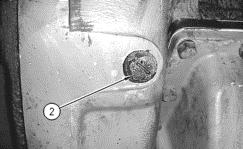
Illustration 2
g00600543 2. Remove plug (2) from the right hand side of the flywheel housing.
Illustration 3
g00600554 3. Install 4P-5820 Pickup Assembly (3) in the flywheel housing.
Illustration 4
g00600612 4. Install two pin connector (4) from the 165-1594 Harness Assembly to the 4P5820 Pickup Assembly (3).
5. Install the wire tie-wraps in order to secure the wiring harnesses.
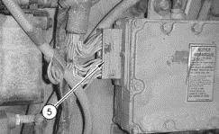
Illustration 5
g00600636 6. Remove the P4 connector (5) from the ECM.
Illustration 6
g00601086 7. Use the following procedure to install the wiring for the electronic control module (ECM): a. Remove the green wire "6711" (Z) from pin "28". Wrap electrical tape around the end of this wire because the wire will not be used.
b. Remove the yellow wire "6704" (W) from pin "18".
Illustration 7 New Wiring Schematic At The ECM g00600703
c. Install the yellow wire "6704" in pin "28". See the new wiring schematic.
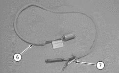
Illustration 8 g00600780 d. Connect 165-1595 Harness Assembly (6) to the 165-1594 Harness
Assembly.
e. Install white wire (7) from the 165-1595 Harness Assembly in pin "18".
See the new wiring schematic.
f. Remove the green wire "6121" (Y) from pin "1".
g. Install the red wire from 165-1595 Harness Assembly to pin "1". See the new wiring schematic.
h. Install the green wire "6121" in the red splice of the 165-1595 Harness
Assembly. See the new wiring schematic.
i. Remove the black wire "6202" (X) from pin "21".
j. Install the black wire from 165-1595 Harness Assembly to pin "21". See the new wiring schematic.
k. Install the black wire "6202" in the black splice of the 165-1595 Harness
Assembly. See the new wiring schematic.
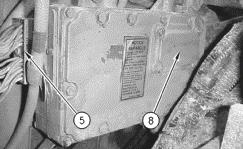
Illustration 9
g00600853 8. Install P4 connector (5) to the ECM. 9. Remove cover (8) from the ECM. 10. Remove the personality module from the ECM. 11. Install a new personality module. See Table 1. 12. Install cover (8).
ECN 960712
On-Highway Truck Vehicle Speed Tip – Erratic Cruise
There have been several instances where drivers of on-highway trucks would complain of erratic cruise control or loss of power as the truck’s vehicle speed approached the programmed vehicle speed limit. The dealership personnel would find that there were no logged vehicle speed faults and the vehicle speed circuitry checked out OK.
One possible solution to these problems is to tighten the nut that secures the yoke to the output shaft of the transmission. When this nut loosens, the chopper wheel can slip causing the ECM to see a slower than actual vehicle speed. The ECM increases the fuel rate to get the vehicle back to the desired vehicle speed. By the time the chopper wheel catches up and sends out the correct vehicle speed, the truck may have exceeded the programmable vehicle speed limit causing the ECM to cut the fuel rate. The same thing happens when cruise control is used. The chopper wheel slips causing the ECM to register a slower than actual vehicle speed. The ECM increases the fuel rate to get the truck back to the set speed. The chopper stops slipping and
sends out the true vehicle speed, which is now higher than the set speed and the ECM cuts the fuel rate back – and the cycle repeats.
If the chopper wheel can be rotated with a screwdriver, it is too loose. (Some chopper wheels have been loose enough to rotate with a finger.) Tighten the nut on the output shaft of the transmission to the torque specified by the manufacturer.
Truck Engine News
Media Number - SEBD6612-00 Publication Date - 1990/09/01
3176 And 3406B (PEEC) Truck Engines Reference: Service Manual Module, 3406B (PEEC) Truck Engine Test Procedures, SENR3479. Service Manual Module, Electronic Troubleshooting 3176 Diesel Truck Engine, SENR3913.
The throttle adjustment procedure is critical to insure proper engine performance. Some engines equipped with 9X9647 or 9X9648 Throttle Position Sensors (TPS) have experienced problems because the throttle linkage was not adjusted correctly. When incorrectly adjusted, the engine may experience low power, or in the worst case, "cutout" when fully loaded. Incorrect adjustment can cause the TPS rotary disk to travel beyond normal operating ranges. If the rotary disk travels too far (over rotates), the engine will "cutout" when fully loaded. If the rotary disk does not travel far enough (under rotates), full throttle will not be reached.
Incorrect adjustment cannot be detected with the Electronic Control Analyzer Programmer (ECAP) status display for throttle position. To verify correct TPS adjustment, connect the ECAP or Digital Diagnostic Tool (DDT) to the output of the TPS with the 8C9801 PWM Signal Adapter Group. Set the service tool to display the screen for duty cycle measurement of the pulse width modulated signal. Adjust the throttle linkage to get a low idle reading of 15 to 20% duty cycle and a high idle reading of 80 to 85% duty cycle. This adjustment may have to be performed several times before both low and high idle adjustment ranges are achieved at the same time.
For more details on the correct throttle adjustment procedure, see the Reference.
C. Engine Shutdowns
Engine shutdowns have occurred on 3406B and C PEEC engines. The following can cause these shutdowns:
- OEM Wiring - Kysor Shutdown System - Rack system wear - Shutoff solenoid’ - Personality module - ECM - Rack BTM - Engine Speed Sensor - Transducer module - Rack sensor
For engine shutdowns use Troubleshooting Procedure P-110 and P-308 for the 3406B and C engines respectively. These procedures are included in this manual.
For additional tips and short cuts refer to the Intermittent Failure Analysis Manual (SENR6425).
Remember: Troubleshooting an engine that won’t start is easier than troubleshooting and engine with and intermittent problem.
A Truck Engine News article on the Kysor Shutdown System is also included in this manual.
Troubleshooting
3406B (PEEC) PROGRAMMABLE ELECTRONIC ENGINE CONTROLS
Media Number - SENR3479-05 Publication Date - 1991/02/01 Date Updated - 1997/01/06
P-110: Intermittent Engine Shutdowns
NOTE: Use this procedure ONLY if the engine completely shut down and needed to be restarted using the key switch.
Probable root causes:
* Poor Connection
* Battery power or ground to ECM (vehicle wiring).
* After Market shutdown device (PEEC does NOT have engine protection shutdown feature).
* Fuel supply
* Shutoff solenoid
* Shorted 8-volt sensor supply voltage
* Rack controls
* Engine speed sensor
* ECM or Personality Module Perform the following tests in order:
1. Check external PEEC harness and connectors (refer to P-201: Inspecting Electrical Connectors). * Vehicle connector (J2/P2)
* ECM/Sensors connector (J3/P3)
* ECM/Solenoids connector (J4/P4)
* Transducer connector (J5/P5)
* Rack solenoid connector (J10/P10)
* Shutoff solenoid connector (J11/P11) 2. P-210: Electrical Power Supply to PEEC Test
3. Check for proper installation and operation of shutdown devices.
4. P-223: Shutoff Solenoid Test
5. Check fuel tanks for foreign objects that may block fuel supply.
6. Bypass OEM wiring and shutdown devices for testing. Refer to P-210: Electrical Power Supply To PEEC Test.
7. Check the following for damaged or abraded 8-volt sensor supply wires: * Timing position sensor
* Rack position sensor
* Engine speed sensor
* Transducer module (on wires in governor housing)
* PEEC engine harness 8. P-232: Rack Solenoid (BTM) Test
9. P-231: Rack Position Sensor Test
10. P-222: Engine Speed Sensor Test
11. P-220: ECM And Personality Module Test.
Troubleshooting
3406C (PEEC III) DIESEL TRUCK ENGINE
Media Number - SENR5503-00 Publication Date - 1992/12/01 Date Updated - 1997/01/06
P-308: Intermittent Engine Shutdowns Probable Root Causes: Perform the following tests:
Note: Use this procedure ONLY if engine shutdown completely and had to be restarted using the key switch.
1. Poor electrical connections……… Check external PEEC III wiring harness and connectors (refer to P-500: Inspecting Electrical Connectors): ECM connector (J4/P4), Vehicle connector (J7/P7), Transducer connector (J5/P5), Rack solenoid connector (J3/P3), Shutoff solenoid connector (J13/P13).
2. Battery power or ground to ECM (vehicle wiring)… P-501: Electrical Power Supply 3. After market engine protection devices Check for correct installation and operation of engine protection devices. 4. Fuel Supply…………… Check fuel tanks and lines for foreign objects that may block fuel supply. 5. Shutoff Solenoid……… P-513: Shutoff Solenoid 6. Shorted 8-volt sensor supply voltage…….. By-pass OEM wiring and shutdown devices for testing (refer to P501: Electrical Power Supply to PEECIII). Check the following for damaged or abraded 8-volt sensor supply wires: Timing position sensor, Rack position sensor, Engine speed sensor, Transducer module (wires in governor housing), PEEC III engine harness.
7. Rack controls………… P-522: Rack Solenoid (BTM) P-521: Rack Position Sensor 8. Engine Speed sensor…………. P-512: Engine Speed Sensor 9. ECM or Personality Module…………. P-510: ECM & Personality Module
Truck Engine News
Media Number - SEBD6581-00 Publication Date - 1988/02/01
Servicing And Programming PEEC Truck Engines Equipped With Kysor ® Shutdown System
3406B PEEC Truck Engines Equipped With Shutdown System Reports indicate a problem servicing and programming a 3406B (PEEC) Truck Engine equipped with a Kysor ® Engine Shutdown System. The Kysor® Engine Shutdown disconnects the Programmable Electronic Engine Control (PEEC) voltage supply when the engine is without oil pressure for a specified amount of time (approximately 30 seconds). This results in an inability to program and service the PEEC system.
Servicing and programming the PEEC can be accomplished by supplying power directly to the PEEC. This can be done as follows.
1. Remove the "A" wire from the J2 connector with a Deutsch pin remover (part to the 1U5803 Deutsch Connector Repair Kit).
2. Attach an 8T8729 Pin to a 16 AWG jumper wire and insert the pin into "A" position of the J2 connector.
3. Connect the other end of the jumper wire to a battery positive (+) source.
4. Connect power to the Throttle Position Sensor and the Vehicle Speed Buffer. In most cases (dependent on OEM wiring) this can be done by connecting a jumper wire from a battery positive (+) source to "A" wire removed in Step 1. An 8T8730 Socket can be used to connect the jumper wire to the 8T8729 Pin on the end of wire "A". NOTE: Be sure to keep all contacts isolated from any grounded surface. When power is supplied to all units of the PEEC system, normal servicing and programming capabilities are restored. When servicing and programming are complete, remove the jumpers and install wire "A" in position "A" in the J2 connector. Be sure the 8T8729 Pin is fully installed in the connector. The pin must withstand a pull of 10 pounds and still remain in place in the connector body.
D. Low Power/Restricted RPM
For low power, reference procedures P-106 thru P-107 (3406B) and P-305 thru P-306 (3406C).
For engines with serial number prefix of 8TC Cold Mode that can limit engine RPM at start-up and after a loss of battery voltage to the ECM.
- No coolant temp sensor. ECM asks for timing advance during start-up and based on the response of the timing system the ECM guesses the thickness of the to determines if cold mode should be used. - This check lasts for about 10 seconds. If the throttle is touched during the check, then cold mode is assumed and low power with 1700 RPM limit is started. - ECM does this every time the ECM is powered-up (if vehicle speed is less than 30 mph, engine is in low power during cold mode).
A Truck Engine News article on bonnet and barrel cleaning is included as well.
For low power PEEC engines there is also a rack linearity procedure. Rack sensors have occasionally become “non-linear”. In this situation they will typically send the ECM a signal that does not represent actual rack travel. For instance the rack sensor may “tell the ECM” that it is at 15mm of travel when it is actually at 12mm. This error results in low power. This problem does not occur every time the rack is increased.
Verify that the rack sensor has not failed using this procedure: Rack reading on ET should be compared to a dial indicator installed in the fuel pump. One millimeter of dial indicator travel should cause an increase of 1mm on ET. If the increase displayed on ET varies greatly (>0.3mm) from that of the dial indicator, then the rack sensor has become non-linear and may be causing low power. See the attached Truck Engine News article.
Troubleshooting
3406B (PEEC) PROGRAMMABLE ELECTRONIC ENGINE CONTROLS
Media Number - SENR3479-05 Publication Date - 1991/02/01
P-106: No Or Poor Response To Throttle
Probable root causes:
* Active Diagnostic Codes
* PEEC Self-Checks or Cold Mode (normal operation)
* Progressive Shift Parameters (normal operation)
* Acceleration Rate Limit (normal operation)
* Throttle position signal
* Rack subsystem
* Vehicle speed signal
Date Updated - 1997/01/06
Perform the following tests in order:
1. Troubleshoot any ACTIVE diagnostic codes. Codes 32 and 56 limit engine speed to low idle.
2. Verify that PEEC has completed its start-up self-checks and is out of Cold Mode.
3. Check Progressive Shift Parameters to verify that they are not the cause of the complaint.
4. If complaint is around 1500 to 1600 rpm, the cause may be PEEC's Acceleration Rate Limit (normal operation). Refer to the section Summary Of PEEC Personality Modules Changes to determine if the Personality Module has ARL.
5. P-211: Throttle Position Sensor Test
6. P-231: Rack Position Sensor Test
7. P-232: Rack Solenoid (BTM) Test
9. P-213: Vehicle Speed Signal Test
Probable root causes:
* Active Diagnostic Codes
* Customer Parameters (normal operation)
* PEEC Self-Checks or Cold Mode (normal operation)
* Throttle position signal
* Fuel supply restrictions
* Inlet air system problems
* Exhaust system restrictions
* Boost pressure signal
* Rack controls
* Timing advance
* Vehicle speed signal
Perform the following tests in order:
1. Troubleshoot any ACTIVE diagnostic codes and LOGGED Codes * Codes 24 and 46 limit engine speed to 1350 rpm.
* Codes 31 and 36 limit engine speed to "Engine RPM At VSL".
* Codes 22, 23, 25, 42, 43, and 44 limit engine power.
* Code 48 limits engine speed to 1350 rpm in gear even if it is only LOGGED and not ACTIVE. 2. Verify that complaint is NOT due to parameters. * Check Progressive Shift Parameters, Vehicle Speed Limit, and Top Engine Limit.
* Verify that Full Load Setting and Full Torque Setting are programmed to the values stamped on the engine information plate.
3. Verify that PEEC has completed its start-up self checks and is out of Cold Mode.
4. P-211: Throttle Position Sensor Test
5. Check for proper fuel pressure and fuel return flow.
6. Check for air system problems:
* plugged air filter
* aftercooler restrictions
* aftercooler leaks
* high intake air temperature 7. Check for exhaust system restrictions.
8. P-224: Boost Pressure Sensor Test
9. P-230: Dynamic Rack Controls Test
10. P-240: Dynamic Injection Timing Test
11. P-213: Vehicle Speed Signal Test
12. Run PAR (Performance Analysis Report) Test.
Troubleshooting
3406C (PEEC III) DIESEL TRUCK ENGINE
Media Number - SENR5503-00 Publication Date - 1992/12/01 Date Updated - 1997/01/06
P-305: No or Poor Throttle Response Probable Root Causes: Perform the following tests:
1. Active Diagnostic Codes……… Troubleshoot and ACTIVE diagnostic codes 2. PEEC III Self-Checks or Cold Mode (normal operation)… Verify that PEEC III has completed its start-up self-check and is out of cold mode 3. Progressive Shift Parameters……….. Check Progressive Shift Parameters to verify that they are not the cause of the complaint. 4. Throttle position signal…………… P-502: Throttle Position Sensor 5. Rack sub-system……… P-521: Rack Position Sensor P-523: Rack Solenoid (BTM) 6. Vehicle Speed Signal…….. P-504: Vehicle Speed Signal
P-306: Low Power/Engine RPM Restricted/Will not reach VSL Probable Root Causes: Perform the following tests:
1. Active Diagnostic Codes……… Troubleshoot and ACTIVE or LOGGED diagnostic codes. Code 24, 46, and 48 limit engine RPM to 1350. Code 36 limits engine RPM to "Engine RPM at VSL". Codes 22, 23, 25, 43, 44, 61, and 62 limit engine power. 2. Customer Parameters……….. Verify that the complaint is NOT due to parameters. Check Progressive Shift, Vehicle Speed Limit, and Top Engine Limit. Verify that the Full Load Setting and the Full Torque Setting are programmed to the values stamped on the engine information plate.
3. PEEC III Self-Checks or Cold Mode (normal operation)…
Verify that PEEC III has completed its start-up self-check and is out of cold mode 4. Throttle position signal…………… P-502: Throttle Position Sensor 5. Fuel supply restrictions………….. Check for proper fuel pressure/fuel return flow. 6. Inlet air system problems……….. Check for air system problems: Plugged air filter, Aftercooler restrictions, Aftercooler leaks, High intake air temperature. 7. Exhaust system restrictions……… Check for exhaust system restrictions 8. Boost pressure signals………….. P-514: Boost Pressure Sensor 9. Rack Controls…………. P-520: Dynamic Rack Controls 10. Timing Advance……… P-533: Dynamic Injection Timing 11. Vehicle Speed Signal……. P-504: Vehicle Speed Signal
Truck Engine News
Media Number - SEBD6676-00 Publication Date - 1996/03/27
Fuel Injection Pump Barrel Sealing Face Reconditioning
1251
3406 Truck Engines Equipped With New Scroll Fuel System (NSFS) This article provides information for a new chemical cleaning process for the fuel injection pump bonnet and barrel sealing surfaces. Either chemical cleaning or lapping may be used to recondition the barrel sealing surfaces. Laboratory and field-testing have shown the chemical cleaning process is less subjective and results in better sealing than the hand lapped parts.
Before beginning the Sealing Face Chemical Cleaning Process, do the Precleaning Inspection. Replace 2W-2409 and 6I-1665 Bonnets with new 108-2102 Bonnets. Precleaning Inspection
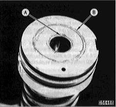
Illustration 1. Top View Of Barrel A. Do not reuse if the check valve seating surface is nicked.
B. Staining here is acceptable. The new bonnet seal ring is inside this diameter. There is no need to remove light to moderate stains in this area.
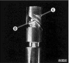
Illustration 2. Plunger NOTE: Do NOT mix plungers and barrels. The original plungers must remain with the same barrels. If the plunger is not acceptable, a new pump group is required. Do not proceed with this process if the plunger is not acceptable.
C. Cavitation erosion above the scroll edge is acceptable.
D. Plungers with worn or nicked scroll edges should not be reused.

Illustration 3. Top View Of Barrel E. A mirror image of the check valve notch is acceptable.
E. Heavy staining should be removed to prevent debris from getting into the sealing joint during assembly. Visible staining "Not Easily Removed" is acceptable because the new bonnet seal ring is inside this diameter.
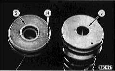
Illustration 4. Bottom View Of Bonnet (Left). Top View Of Barrel (Right) G. This style bonnet can have staining removed with the same cleaning process and reused.
H. Multiple relief notches are acceptable.
J. Light staining and fretting is not an automatic indication of joint leakage. This should be cleaned before reuse.

Illustration 5. Top View Of Barrel K. Staining and/or fretting "Before" cleaning.
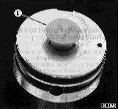
Illustration 6. Top View Of Barrel L. A 7000 Series nozzle tip cap in the barrel bore will help keep the cleaning fluid on the surface. Remove the cap and flush the barrel with clean diesel fuel after cleaning. The chemical cleaning will remove surface stains, but fretting will remain. Laboratory and field test indicate a new style bonnet combined with increased bushing tightening torque [300 N·m (220 lb ft)] will seal with a fretted barrel.
NOTE: The bushing tightening torque of 300 N·m (220 lb ft) is for used plungers and barrels with face fretting ONLY. Use the standard bushing tightening torque of 260 N·m (190 lb ft) in all other cases.

Illustration 7. Timing Spacer M. Debris dent in a timing spacer. Do not reuse. Manufacturing grind marks are acceptable and lapping is not required.