6 minute read
Steering Gear Box

POWER STEERING FILTER
Capacity of Power Steering System ----------------- 4-1/4 Pints Type Fluid -------------- Auto111atic Transmission Fluid - Type A
! FIiter Ejlement
Change Interval -- 1000 hours (mo ,e often in severe dust conditions)
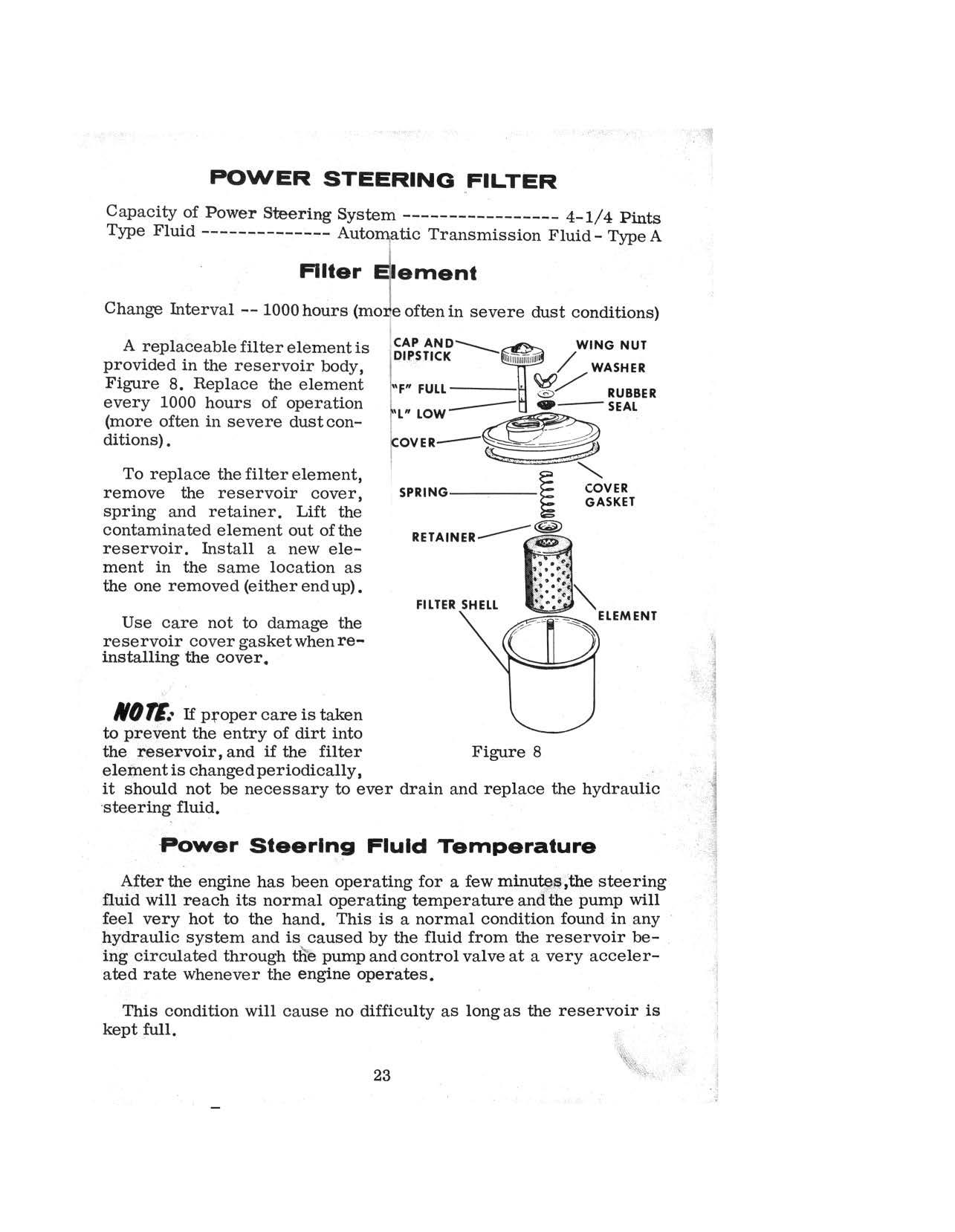
A replaceablefilterelementis !cAP AND----. WING NUT provided in the reservoir body, IDIPSTICK 111 filiiiiiiT1i111 / WASHER Figure 8. Replace the element 'F" FULL · ~/ RUBBER every 1000 hours of operation --- •- SEAL (more often in severe dust con- t'L" LOW ~Ft ditions). k ovER-- ~ . . . .:'~ .. .. · ---- 9 .·
To replace the filter element, l remove the reservoir cover, spring and retainer. Lift the contaminated element out of the reservoir. In.stall a new element in the same location as the one removed (either end up).
SPRING-----~ COVER
. GASKET (@)
RETAINER----,~
FILTER SHELL
Use care not to damage the reservoir cover gasket when reinstalling the cover.
110 TE.• If pfoper care is taken to prevent the entry of dirt into the reservoir, and if the filter Figure 8 element is changed periodically, it should not be necessary to ever drain and replace the hydraulic ·steering fluid.
Power Steering Fluld Temperature
After the engine has been operating for a few minu~ffe;the steering fluid will reach its normal operating temperature and the pump will feel very hot to the hand. This is a normal condition found in any hydraulic system and is caused by the fluid from the reservoir being circulated through tlie pump and control valve at a very accelerated rate whenever the engine operates.
This condition will cause no difficulty as long as the reservoir .is kept full.
23
I
!' ! t.
FIiiing Reservolrr Bleedlng Air from Power Ste.-rlng System
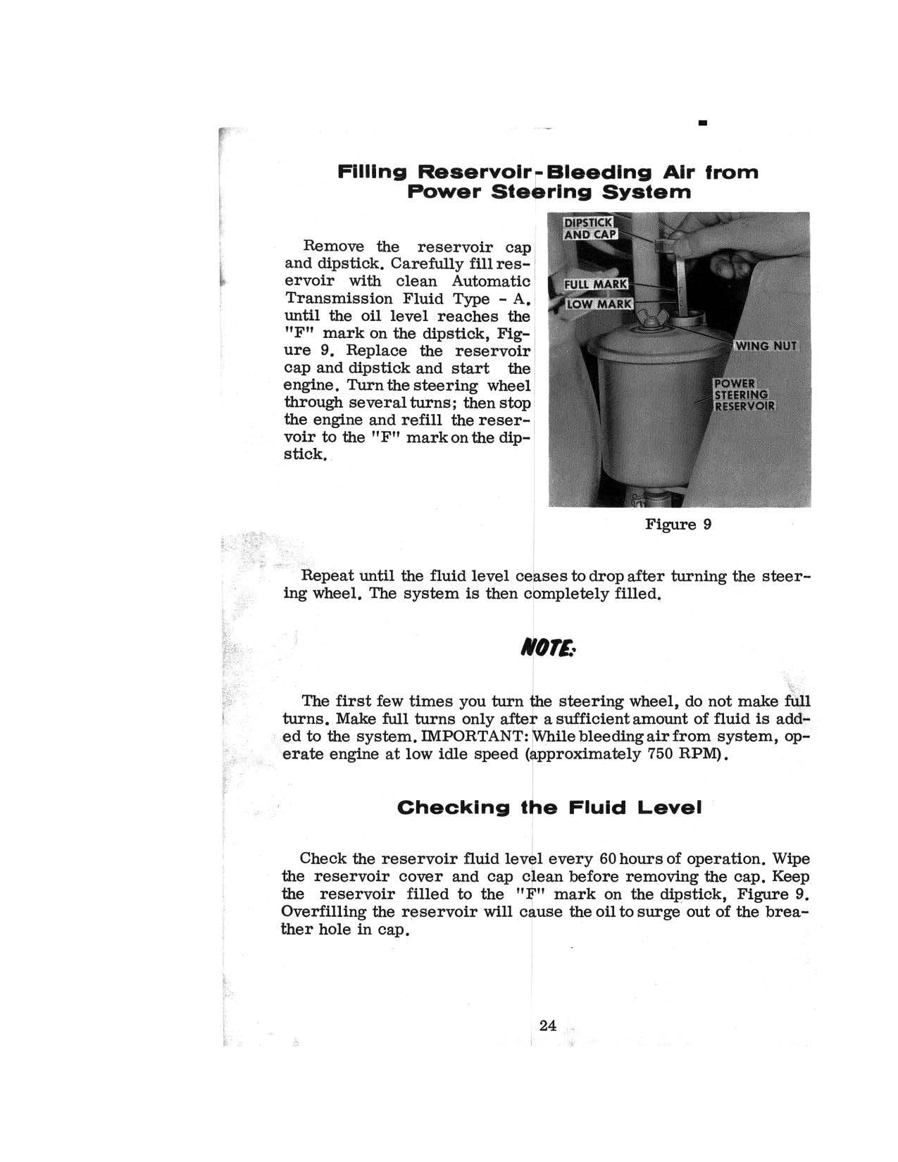
Remove the reservoir cap I and dipstick. Carefully fill reservoir with clean Automatic . Transmission Fluid Type - A. I until the oil level reaches the 1 "F" mark on the dipstick, Figure 9. Replace the reservoir cap and dipstick and start the engine. Turn the steering wheel 1 through several turns; then stop . the engine and refill the reser-: voir to the "F" mark on the dip- I stick, .
Figure 9 ·
·-·•· . Repeat until the fluid level ce ses to drop after turning the steering wheel. The system is then c, mpletely filled.
I
,OTE.•
The first few times you turn ~e steering wheel, do not make ~ 1 turns. Make full turns only after_! sufficient amount of fluid is add• ed to the system. rMPORTANT: [While bleeding air from system, op;..· erate engine at low idle speed (approximately 750 RPM).
Checking t~e Fluld Level
Check the reservoir fluid levl l every 60 hours of operation. Wipe I the reservoir cover and cap c~ean before removing the cap. Keep the reservoir filled to the "~" mark on the dipstick, Figure 9. Overfilling the reservoir will cause the oil to Surge out of the breather hole in cap.
24
I
TRANSMISSION AND CONVERTER OIL AND FILTER CHANGE
1. Remove the drain plug from the transmission, Figure 10.
Figure 10
2. Reniove the transmission oil strainer, Figure 10 and clean with mineral spirits using a soft bristle brush. Reinstall clean strainer in transmission.
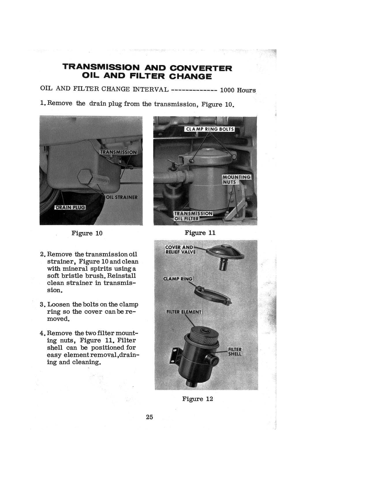
3. Loosen the bolts on the clamp ring so the cover can be removed.
4. Remove the two filter mounting nuts, Figure 11. Filter shell can be positioned for easy element removal,draining and cleaning.
25
Figure 11
Figure 12
j
5. Flush out the filter body with clean fuel before installing the new filter element. After installing the new element, position the shell on the mounting bolts, reinstall the cover, clamp ring and ·bolts, Figure 11.
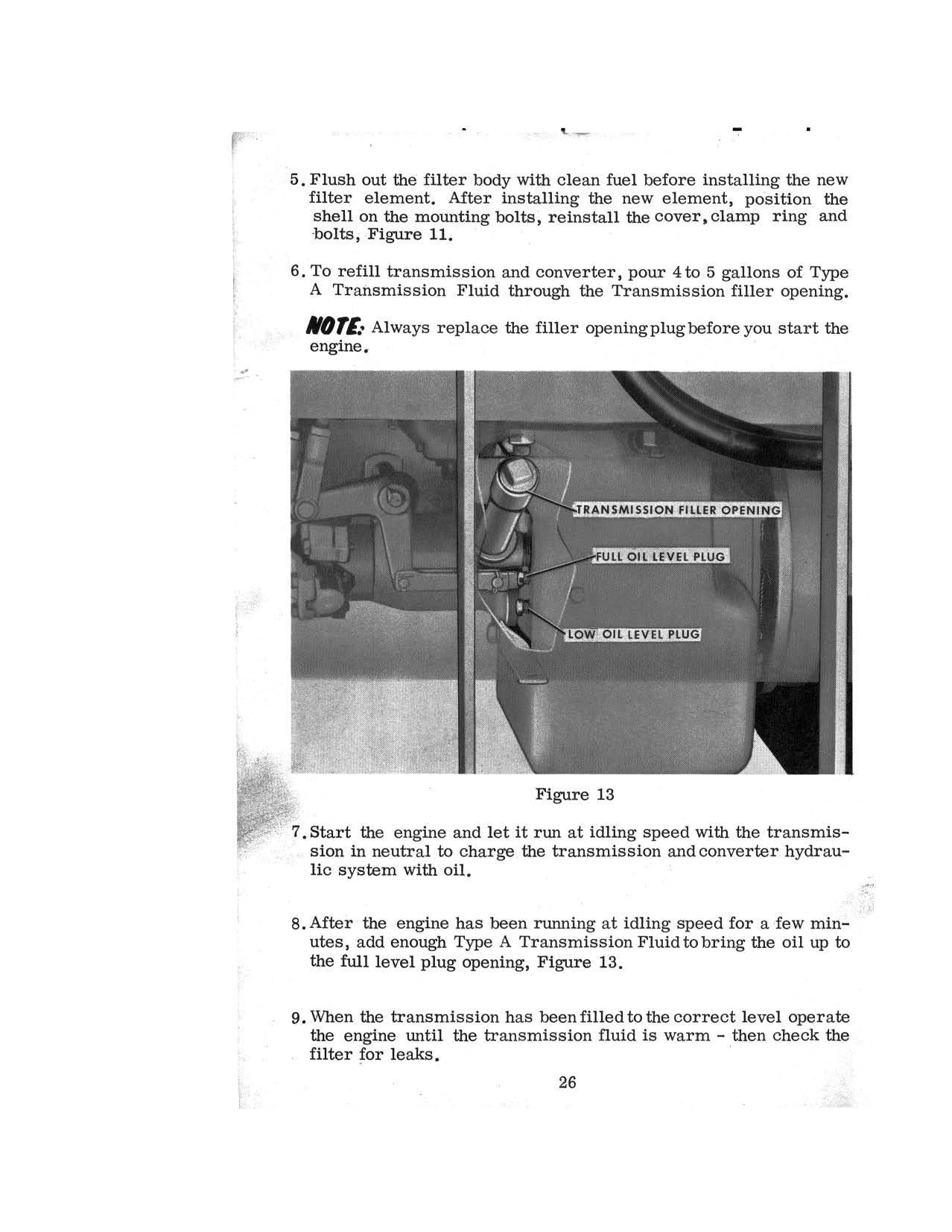
6. To refill transmission and converter, pour 4 to 5 gallons of Type
A Transmission Fluid through the Transmission filler opening. /101£• Always replace the filler opening plug before you start the engine.
Figure 13
· · 7. Start the engine and let it run at idling speed with the transmission in neutral to charge the transmission and converter hydraulic system with oil.
8. After the engine has been running at idling speed for a fow minutes, add enough Type A Transmission Fluid to bring the oil up to the full level plug opening, Figure 13.
9. When the transmission has been filled to the correct level operate the engine until the transmission fluid is warm - then check the filter for leaks.
26
HYDRAULIC RESERVOIR FILTER ELEMENTS
Change Interval -------------------------------- 1000 Hours
Remove the inlet and outlet filter element each 1000 hours of operation (each time the reservoir oil is changed.)
Figure 14
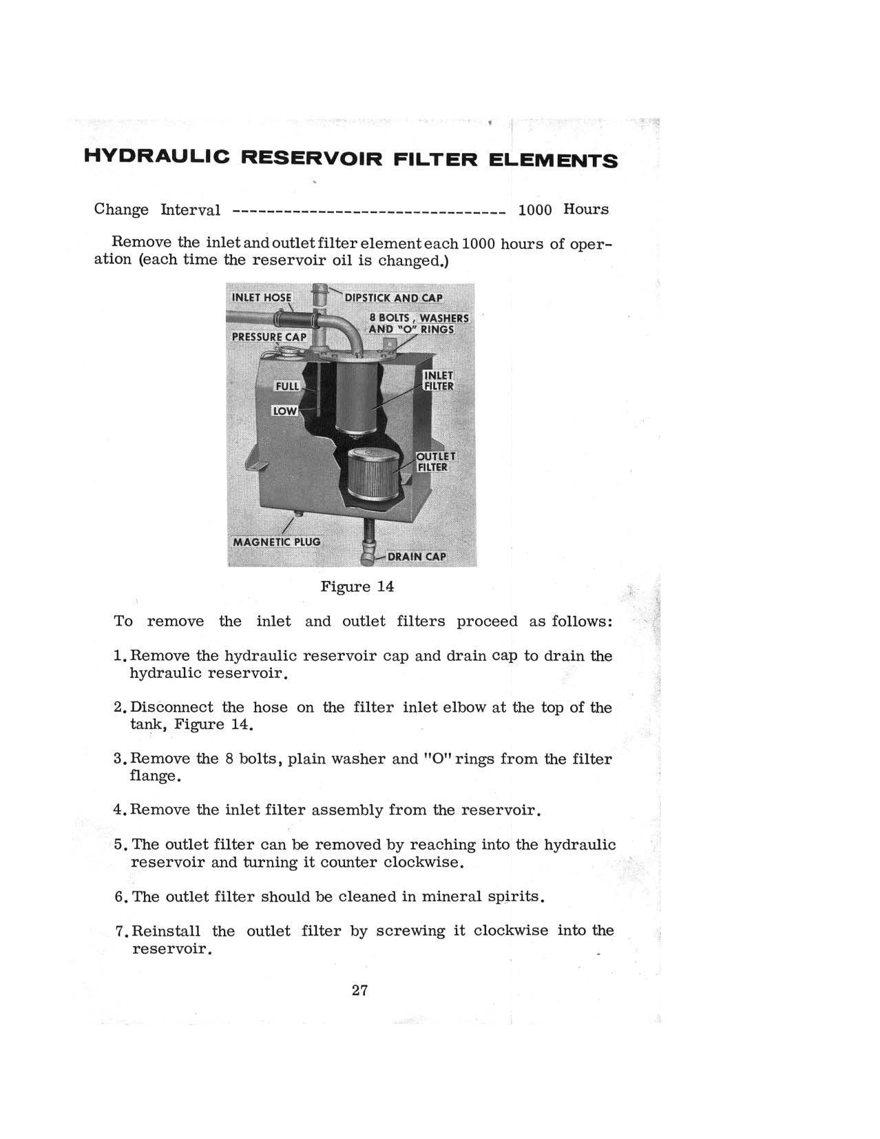
To remove the inlet and outlet filters proceed as follows:
1. Remove the hydraulic reservoir cap and drain cap to drain the hydraulic reservoir.
2. Disconnect the hose on the filter inlet elbow at the top of the tank, Figure 14.
3. Remove the 8 bolts, plain washer and "0" rings from the filter flange.
4. Remove the inlet filter assembly from the reservoir.
5. The outlet filter can be removed by reaching into the hydraulic reservoir and turning it counter clockwise.
6. The outlet filter should be cleaned in mineral spirits.
7. Reinstall the outlet filter by screwing it clockwise into the reservoir.
27
To install a new filter element on the inlet filter flange:
1. Remove the two Flexloc nuts, the filter retainer and relief valve assembly.
2. Wash the parts of the filter assembly before installing new fil-. ter element.
3. Install new filter, two gaskets, retainer and new
Flexloc nuts. Tighten the
Flexloc nuts evenly until end play is out of the filter element. Then torque the
Flexloc nuts to 30 to 35 in. lbs.
FILTER FLANGE-....
4. Reinstall filter flange assembly to the reservoir using a new flange gasket.
Make sure the eight "0" rings and plain washers are installed when the bolts are installed.
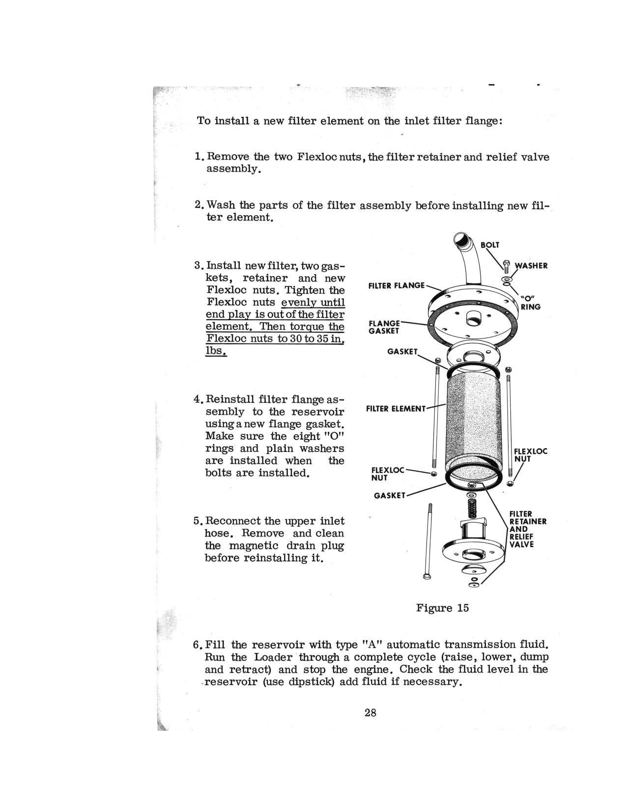
5. Reconnect the upper inlet hose. Remove and clean the magnetic drain plug before reinstalling it.
FLEXLOC-NUT
GASKET
Figure 15
6. Fill the reservoir with type "A" automatic transmission fluid.
Run the Loader · through a complete cycle (raise, lower, dump and retract) and stop the engine. Check the fluid level in the .reservoir (use dipstick) add fluid if necessary.
28
RUN - IN PROCEDURE
IMPORTANT
AT ALL TIMES, KEEP THE ENGINE UP TO THE RECOMMENDED MINIMUM OPERA TING TEMPERATURE (WORK ZONE ON THE TEMPERATURE GAUGE) DO NOT IDLE THE ENGINE
Careful attention must be given to proper "Run-In" procedure. Piston rings and cylinder sleeves can be seriously damaged in a new engine if "Run-In" instructions are not foliowed. The following procedure is recommended:
!.Operating Temperature
Maintain the coolant temperature in the Work Zone on the temperature gauge.
Low operating temperatures contribute to the formation of destructive acids and harmful deposits in the engine.
Adding or removing one or both hood sides will aid in regulating coolant temperature.
Radiator Shutters are available as extra equipment.
2. Crankcase 011
Case Loaders are shipped from the factorywith a special "Run-In" oil in the . crankcase. After the first 20 hours of operation drain this oil while the engine is hot and replace it with fresh oil.
NOT£•
For the next 480 hours, change the crankcase oil at the recommended 120 hour intervals, but use one grade lighter oil than reqommended in the table on Page 16, when the air temperature is above 32°F. Do not drain special run-in oil until the engine has been operated 20 hours. Replace engine filter element after first 120hours of operation and every 240 hours thereafter. Change hydraul\c reservoir inlet filter element and clean the outlet filter after first 20 hours of operation (Run-In) and each time the reservoir oil is changed thereafter. -
29
I