6 minute read
121] Pump-drive assembly .............................................................. 19.1

![1 10] Parking brake parking lock ...................................................... 33.1](https://static.isu.pub/fe/default-story-images/news.jpg)
Basic instructions - Loader arm lock and cab tilt procedure vertical lift machines
SV280 TIER 4B (FINAL) [NFM400877 - ]
W ARNING
Crushing hazard! not enter exit the operator's compartment while the loader arms are raised unsupported. Rest the loader arms the ground verify that loader arm being supported the loader arm strut loader arm lock pin before entering exiting the operator's compartment. Failure comply could result death serious injury .
W1365A
Raise and lock the loader arm for machine service
Sit in the operator's seat, fasten the seat belt, pull down the restraint bar down, and start the engine. Press the operate button enable the hydraulics. Remove the bucket attachment from the mounting plate. Park the machine a level surface.
20092924 1
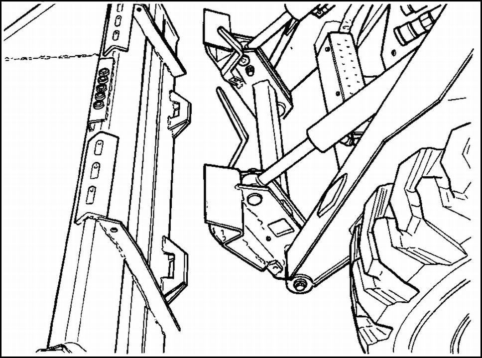
Fully raise the loader arm.
RAPH14SSL0351BA 2
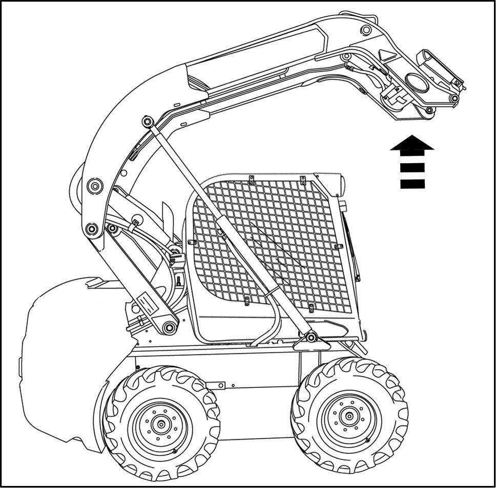
Locate the loader arm lock lever the left - hand side the operator ’s seat. Rotate the lock lever toward the operator ’s seat (clockwise) engage the lock support pin(s). Stop the engine.
Pull the override control knob (red control knob near the right - hand side the operator ’s seat). The loader will brace against the lock support pin and keep the loader arm in a raised position. NOTE: Only use the override control knob lower the loader arm in emergency situations when engine power is not available lower it onto the lock support pin for servicing the machine.
RAIL14SSL0428AA 3
93107457 4
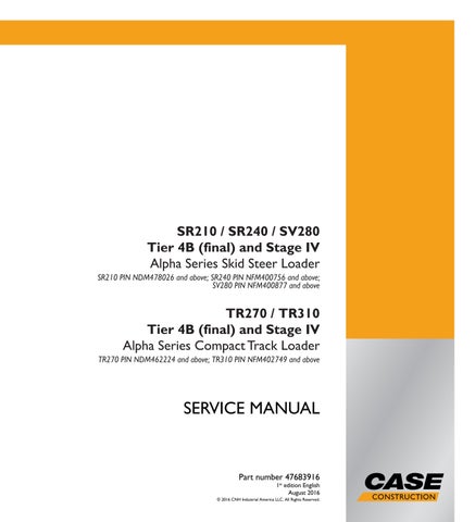
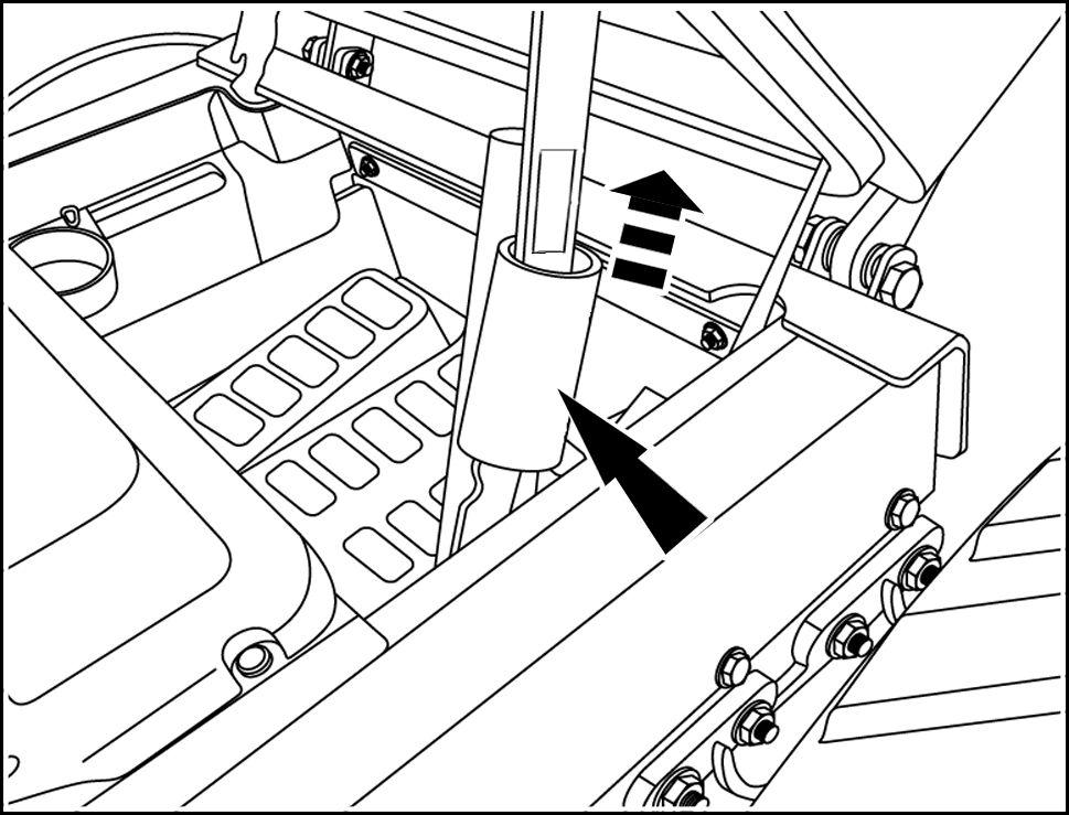
Remove the two, rear retaining nuts, located the rear the cab.
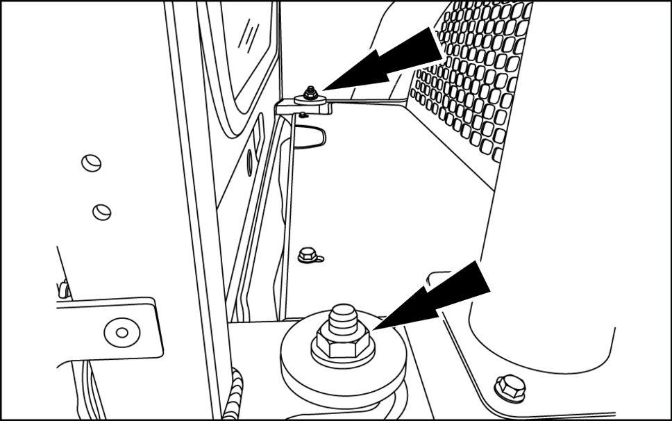
931001633 5
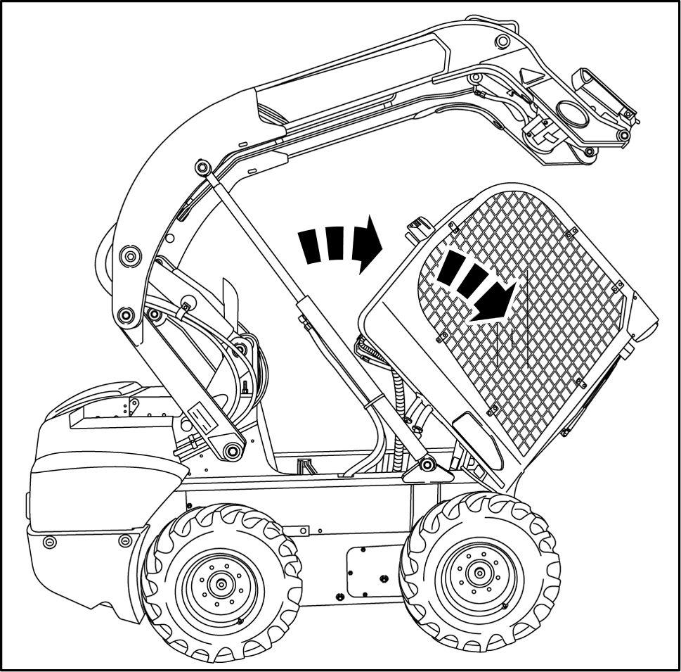
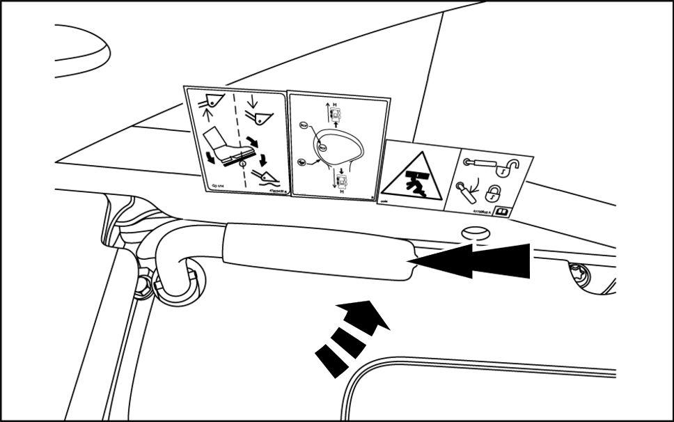
Pull the hand holds the front the machine until the cab is completely tilted forward.
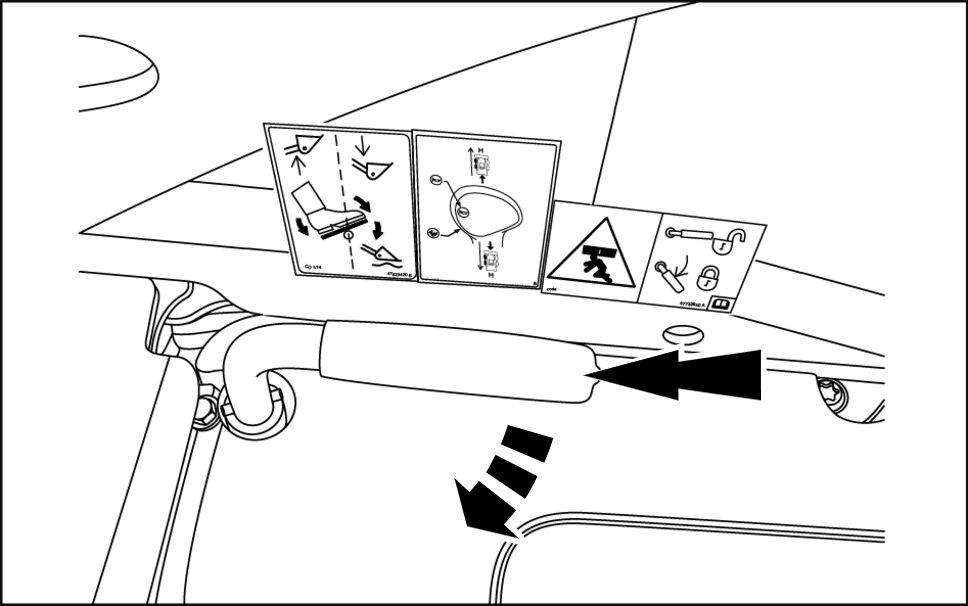
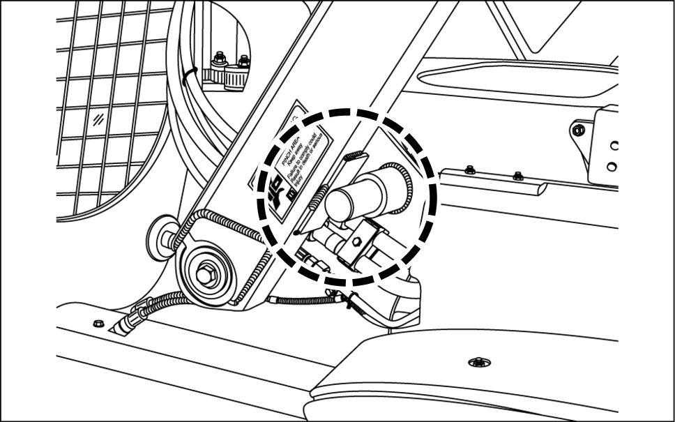
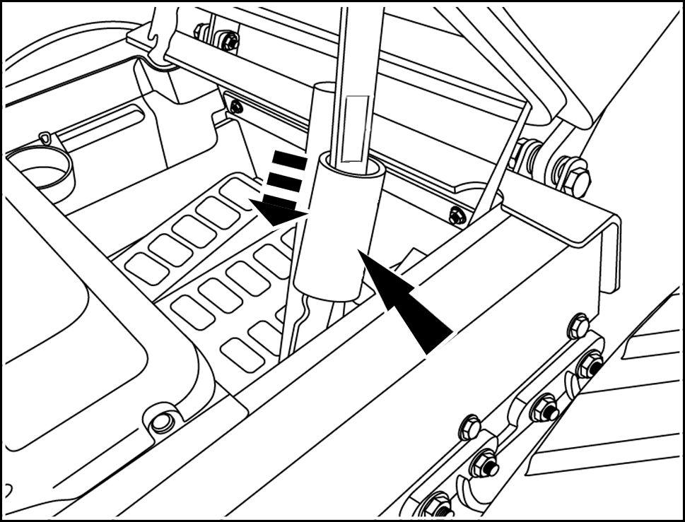
Confirm that the red lock tube has lowered over the cab pivot linkage. it has the cab tilt position is now secure.
RAPH1 1SSL0016BA 6
RAPH12SSL0420BA 7
T ilt and secure the cab for machine operation
Raise the red lock tube exposing the cab pivot linkage. Push the cab backward into the operation position.
RAPH12SSL0420BA 8
Install the retaining nuts. T orque the nuts 170 N·m ( 125 ).
931001633 9
Sit in the operator's seat, fasten the seat belt, pull down the restraint bar down, and start the engine. Press the operate button enable the hydraulics. Fully raise the loader arm.
RAPH14SSL0351BA 10
Rotate the lock lever away from the seat (counter clockwise) retract the lock pin(s). Lower the loader arm. Commence work operations park the machine and stop the engine.
RAIL14SSL0428AA 11
T orque - Standard torque data for hydraulics
SR210 SR240 SV280 TR270 TR310
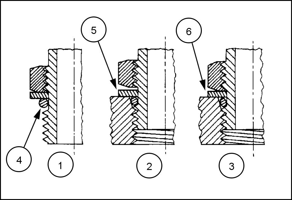
INST ALLA TION ADJUST ABLE FITTINGS STRAIGHT THREAD O RING BOSSES
Lubricate the O- ring coating it with a light oil petroleum. Install the O- ring in the groove adjacent the metal backup washer which is assembled the extreme end the groove (4) . Install the fitting into the SAE straight thread boss until the metal backup washer contacts the face the boss (5) . NOTE: not over tighten and distort the metal backup washer . Position the fitting turning out (counterclockwise) a maximum one turn. Holding the pad the fitting with a wrench, tighten the locknut and washer against the face the boss (6) .
23085659 1
ANDARD T ORQUE TA FOR HYDRAULIC TUBES AND FITTINGS
TUBE NUTS FOR 37° FLARED FITTINGS O- RING BOSS PLUGS ADJUST ABLE FITTING LOCKNUTS, SWIVEL JIC 37° SEA
SIZE TUBING THREAD SIZE T ORQUE T ORQUE
4 6.4 (1/4 ) 7/ - - N·m (9 - ) 8 - N·m (6 - ) 5 7.9 (5/ ) 1/2- - N·m ( - ) - N·m ( - ) 6 9.5 (3/8 ) 9/ - - N·m ( - ) - N·m ( - ) 8 12.7 (1/2 ) 3/4- - N·m ( - ) - N·m ( - ) 15.9 (5/8 ) 7/8- - N·m ( - ) - N·m ( - ) 19.1 (3/4 ) 1-1/ - 104 - 111 N·m ( - ) - N·m ( - ) 22.2 (7/8 ) 1-3/ - 122 - 136 N·m ( - 100 ) - 109 N·m ( - ) 25.4 (1 ) 1-5/ - 149 - 163 N·m (1 - 120 ) 108 - 122 N·m ( - ) 31.8 (1-1/4 ) 1-5/8- 190 - 204 N·m ( 140 - 150 ) 129 - 158 N·m ( - 1 ) 38.1 (1-1/2 ) 1-7/8- 217 - 237 N·m ( 160 - 175 ) 163 - 190 N·m ( 120 - 140 ) 50.8 (2 ) 2-1/2- 305 - 325 N·m ( 225 - 240 ) 339 - 407 N·m ( 250 - 300 )
These torques are not recommended for tubes 12.7 (1/2 ) and larger with wall thickness 0.889 ( 0.035 ) less. The torque is specified for 0.889 ( 0.035 ) wall tubes each application individually . Before installing and torquing ° flared fittings, clean the face the flare and threads with a clean solvent Loctite cleaner and apply hydraulic sealant L OCTITE ® 569 the ° flare and the threads.
Install fitting and torque specified torque, loosen fitting and retorque specifications.
PIPE THREAD FITTING T ORQUE
Before installing and tightening pipe fittings, clean the threads with a clean solvent Loctite cleaner and apply sealant L OCTITE ® 567 PST P IPE S EALANT for all fittings including stainless steel L OCTITE ® 565 PST for most metal fittings. For high filtration / zero contamination systems use L OCTITE ® 545 .
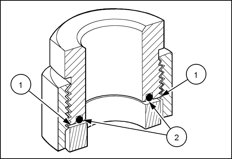
INST ALLA TION ORFS (O - RING FLA T F ACED) FITTINGS
When installing ORFS fittings thoroughly clean both flat surfaces the fittings (1) and lubricate the O- ring (2) with light oil. Make sure both surfaces are aligned properly . T orque the fitting specified torque listed throughout the repair manual. NOTICE: the fitting surfaces are not properly cleaned, the O- ring will not seal properly . the fitting surfaces are not properly aligned, the fittings may damaged and will not seal properly . NOTICE: Always use genuine factory replacement oils and filters ensure proper lubrication and filtration engine and hydraulic system oils.
The use proper oils, grease, and keeping the hydraulic system clean will extend machine and component life.
PIPE THREAD FITTING
Thread Size T orque (Maximum) 1/8- N·m ( ) 1/4- N·m ( ) 3/8- N·m ( ) 1/2- N·m ( ) 3/4- N·m ( )
5001 1 183 2