4 minute read
FUEL SYSTEM


Service Specifications
Fuel Tank Capacity ........................................................................................................................ 341 liters (90 US gal) Interval for draining water from the fuel filter ................................................................................. 50 hours of operation Fuel filter replacement interval ...................................................................... 500 hours of operation or once each year
fuel Conditioner
Diesel fuel conditioner is available from your dealer CAse. Follow the instructions on the can. The conditioner will: 1. Clean the fuel injectors, valves and manifold for increased service life. 2. Disperse insoluble gummy deposits that can form in the fuel system. 3. Separate moisture from the fuel. 4. Stabilize the fuel in storage.
WARNING: Engine fuel is flammable and can cause a fire or an explosion. Do not fill the fuel tank or service the fuel system near an open flame, welding, burning cigars, cigarettes, etc.
fuel filler Cap
Use No. 2 Diesel fuel in the engine of this machine. The use of other fuels can cause the loss of engine power and high fuel consumption. In very cold temperatures, a mixture of No. 1 and No. 2 Diesel fuels is temporarily permitted. See the following note. NOTe: See your fuel dealer for winter fuel requirements in your area. If the temperature of the fuel lowers below the cloud point (wax appearance point), wax crystals in the fuel will cause the engine to lose power or not to start. The Diesel fuel used in this machine must meet the specifications in the chart below or Specification D975-81 of the American Society for Testing and Materials.
fuel storage
If you keep fuel in storage for a period of time, you can get foreign material or water in the fuel storage tank. Many engine problems are caused by water in the fuel. Keep the fuel storage tank outside and keep the fuel as cool as possible. Remove water from the storage container at regular periods of time. Fill the fuel tank at the end of the daily operating period to prevent condensation in the fuel tank.
Specifications for Acceptable No. 2 Diesel Fuel
API gravity, minimum ................................................................................................................................................... 34 Flash point, minimum ................................................................................................................................. 60°C (140°F) Cloud point (wax appearance point), maximum ..................................................................................... -20°C (-5°F) (*) Pour point, maximum ............................................................................................................................ -26°C (-15°F) (*) Distillation temperature, 90% point .................................................................................... 282 to 338°C (540 to 640°F) Viscosity, at 38° C (100° F)
Centistokes ................................................................................................................................................. 2,0 to 4,3
Saybolt Seconds Universal ........................................................................................................................... 32 to 40 Cetane number, minimum ................................................................................ 43 (45 to 55 for winter or high altitudes) Water and sediment, by volume, maximum ........................................................................................................ 0,05 % * see note “Diesel Fuel” on this page.
Open the drain cock, before engine start and allow water or sediment to drain. Close the drain cock when fuel runs out.
fuel filter Replacement
Clean the area around the fuel filter and fuel water separator filter to avoid contamination.
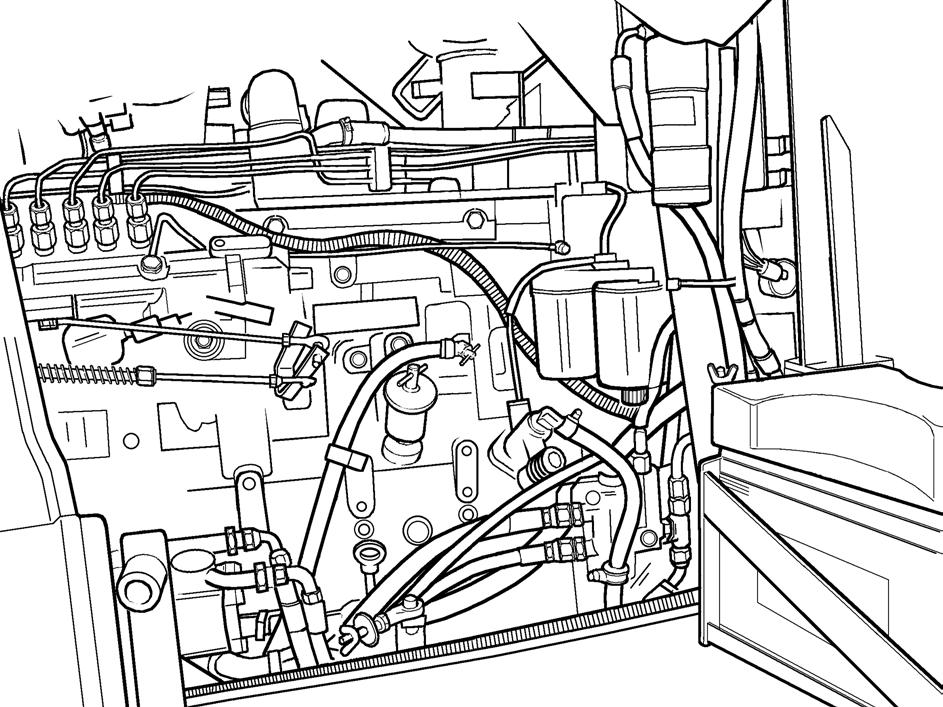
845b MODeLs
2 1
1. 2. FUEL FILTER AND WATER SEPARATOR FILTER FUEL LINE FILTERS
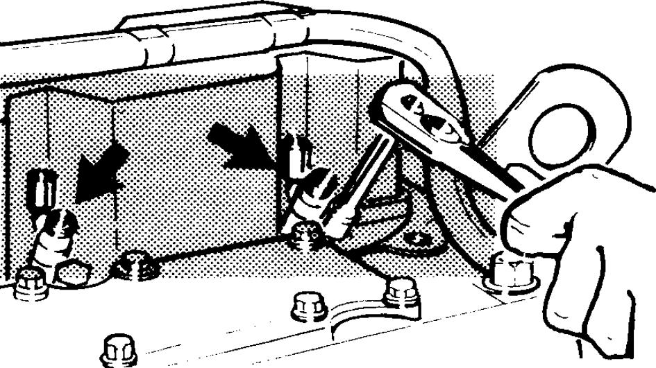
865b AND 885b MODeLs
WARNING: Extinguish all smoking materials or open flames before opening the sediment drain due to presence of flammable fluids.
1 2
1. 2.
FUEL FILTER
WATER SEPARATOR FILTER Remove the filters and clean carefully the area around the filter head gasket. Change the fuel filters and sealing rings. Fill the filters with clean fuel and lubricate the sealing rings with new engine oil. Assemble the filters and tight them manually. After the assembly, make the fuel system air bleed procedure. To drain water from the water separator filter, loose the bolt at the botton of the filter, let the water flows out and tighten the bolt again.
ATTeNTION: Dispose used filters in specialized recycling stations.
fuel Injector Nozzles
Check each 500 hours
FUEL INJECTOR NOZZLES
Remove the fuel lines from top of injectors and cover the fuel lines to prevent contamination. Remove nozzle clamp stud nuts and remove the nozzles from cylinder head. Cover all openings in cylinder head to prevent contamination. The nozzle should be checked by a qualified person in a well equipped shop. The nozzle relief pressure should be 205 bar. Make certain sealing washers are in good condition and seats clean. Install nozzle assemblies in cylinder head, and secure with stud nuts to a torque of 24,5 Nm (18 lbs.ft). Install fuel lines so they are only finger tight (for priming). Crank the engine with starter to bleed the lines then secure fuel line nuts. Check at each fitting for leaks and retighten nuts if necessary to correct leaks.
WARNING: Keep hands away from nozzle tip when popping a nozzle. The finely atomized fuel is ejected with a sufficient force to penetrate the skin and cause blood poisoning. Also, wear safety glasses with side shields or goggles when popping a nozzle.
Adjusting engine Valves
Verify each 1000 hours
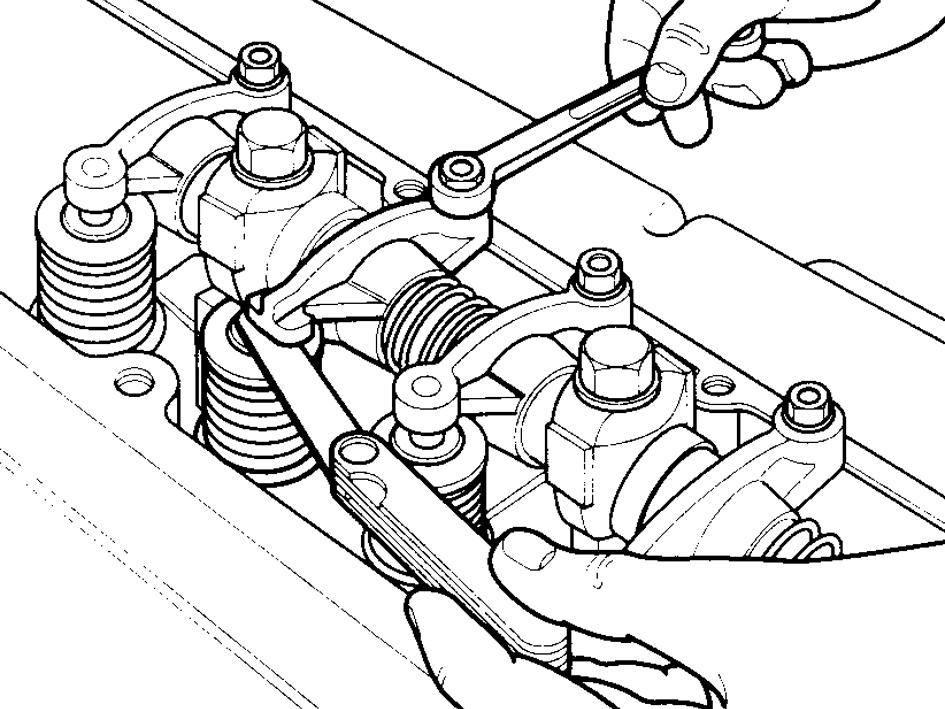
VALVE CLAREANCE
Adjust the valve clearance always when the engine is cold, i.e., the water temperature should be under 60ºC (140ºF). Initially determine the first cylinder top dead center. For that, turn the engine manually and slowly, using a 1/2” square wrench and a manual turning device. The valves clearance must be:
845b MODeLs
Valve clearance with engine cold: Intake ............................................ 0.254 mm (0.010 pol) Exhaust ......................................... 0.508 mm (0.020 pol)
865b AND 885b MODeLs
Valve clearance with engine cold: Intake .............................................. 0.30 mm (0.012 pol) Exhaust ........................................... 0.61 mm (0.024 pol)
NOTe: The clearance will be correct when the feeler gauge is passed between the valve rod and the rocker, with a little resistance.


