10 minute read
OPERATION


This machine and its attachments are to be operated only by a qualified operator stationed at the operator’s controls either seated or standing as conditions require. The use of the seat belt is recommended always, even on the machines equipped with ROPS. Before starting the machine, check, adjust and lock the operator’s seat assembly for maximum comfort and control of the machine. This machine is equipped with power steering which is effective only when the engine is running. If engine fails, stop the machine immediately. For emergency stops, apply foot brakes as required or pull parking/ emergency brake lever. Check the torque of the wheel bolts after every 20 hours of operation until the wheel bolts stay tight, if the machine is new or if a wheel has been removed and installed. Tighten according to procedure and specifications manual instructions. Always travel with the scarifier in the full raised position and lower to the ground when parked. Use extra care when using down pressure on the blade when working on hills, banks and slopes. NOTe: When the Grader wheels have been turned to the maximum (in either direction), do not continue to turn the steering wheel in the same direction. This causes unnecessary wear on pump and valve components of steering system. To start machine motion, raise moldboard, release parking brake, shift into the desired range and direction and move the throttle lever to meet the operational requirements. Select a transmission range that will maintain engine speed appropriate for the load required. Low engine speed can be corrected by downshifting or lightening the load. Over revving the engine should be avoided. Slow the machine by applying the brakes. Incorrect gearshift can result in an accident for the operator as well as damages to the machine and the transmission. Observe the following instructions: 1. Down shift only when the ground speed for the selected range has been achieved. 2. Down shift only one range at a time. WARNING: Do not coast the machine at any time with the transmission in neutral. Do not attempt to decelerate on grades by shifting. Decelerate the engine and apply the foot brakes. Anticipate grades before starting down.
CAUTION: Select the proper gear range to maintain the control. Engage transmission to start up only when the engine is at low idle. Down or up shift only one range at a time and only when the speed of the machine approximates the speed of the next range.
The transmission range and engine speed should be set before beginning the grading operation. Never overload the moldboard, so that the rear wheels begin to slip. This not only alters the grade but causes unnecessary wear to rear tires. Increasing the blade angle (putting one blade tip farther forward than the other tip) will reduce the load. The blade should be set to cast the dirt either inside or outside of the rear wheels, not under the wheels unless it is for compaction purposes. The moldboard pitch can be changed to suit various operations. When the top of the moldboard is tilted forward the cutting edge will not slice the material, but push it. This is advantageous when pushing dirt from one location to another. Tilting the top of the moldboard to the rear will angle the cutting edge so that it will slice and create a bite into the material. This can be advantageous in heavy material because the material will roll against the moldboard, breaking it up and making it easier to move. Using the moldboard to back drag material should be avoided if possible. This can cause heavy wear on the moldboard guides and possibly damage the side shift cylinder piston rod. If back dragging cannot be avoided, make certain material does not contact the positioning piston rod. Worn or poorly adjusted moldboard guides will cause an unstable moldboard for fine grading. When making heavy cuts or moving heavy loads that tend to side shift the Grader, lean the front wheels toward the load to counteract side shift.
NOTe: Remove the scarifier teeth before trying to open or clean a trench. When starting a ditch, position moldboard so that one cutting edge (right or left) is directly behind and 3” (76 mm) below the front wheel, with the other end of the blade as high as possible. Cast the material between the rear wheels. The first cut should be light enough to maintain control of the grader and cut a straight ditch line. When the material accumulates under the machine, it should be cast aside before taking another cut in ditch line. Deeper ditch requires more side casting of material. If a “V” ditch is required, each side of the ditch must be cut alternately to permit the front and rear wheels to travel in the center of the ditch. When it is necessary to cast material over the edge of a fill, side shift the moldboard to its extreme, so that the grader wheels are not on edge of fill. The weight of the machine could cause the edge to give way endangering the operator. Articulation also helps in this situation. When grading a road shoulder, it may be necessary to grade around objects, such as mailboxes abutments or utility poles. The moldboard can be side shifted around the object without changing the grade level.
bank or back sloping
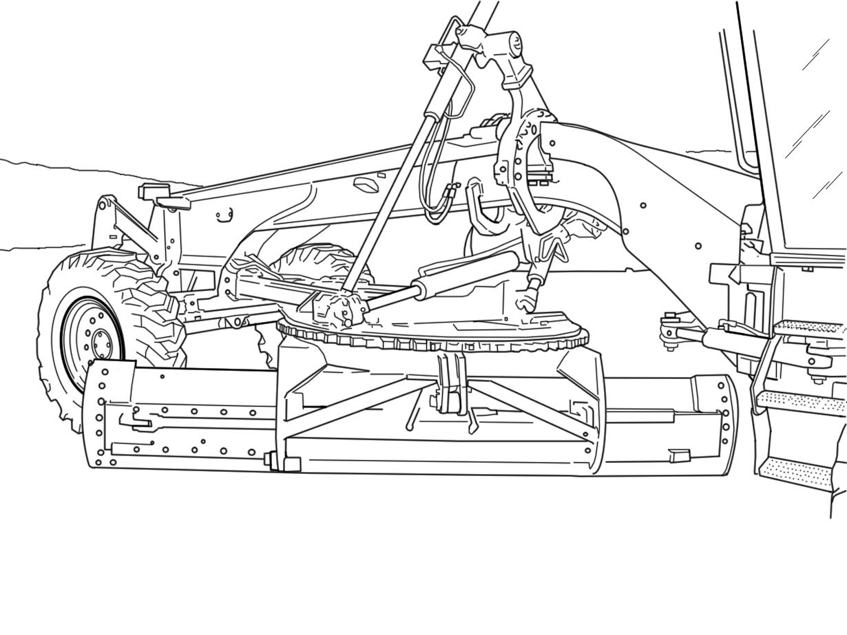
To position the moldboard (in this case to the right side) proceed as follows: 1. Turn the circle until blade is at a right angle (90°) to the grader.
BLADE POSITIONED AT RIGHT ANGLE (90°) TO GRADER 2.
Side shift blade to the extreme right, then side shift the circle until cylinder rod shows about 5” (127 mm) extension. Lower moldboard to the ground.
BLADE POSITIONED AT RIGHT SIDE TO GRADER
3. Disengage the saddle lock pins. Using the blade lift levers, extend the right blade lift cylinder rod and retract the left blade lift cylinder rod (moldboard on the ground). After the saddle has been rotated to the desired position (fully for 90° position), align the saddle pin holes (by sight) and reengage the saddle lock pins.
ROTATING SADDLE 4.
Raise the blade slightly from the ground, then raise the right end of the blade while turning the circle so that right end of the blade moves toward the right front of the grader (this will keep the left end of the blade from hitting the ground) Move simultaneously the circle upwards using the lateral movement lever (in this case, pull backwards the circle side shift lever). NOTe: As the left end of the blade is raised from the ground, it is necessary to lower the left end of the blade and raise the right end of it at the same time.
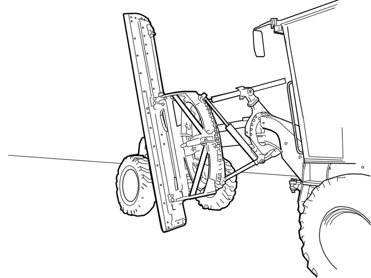
BLADE AT 90° BANK SLOPE INTERMEDIATE POSITION
5.
Continue the operation (as in item 4) until the moldboard is positioned as in the illustration. Then turn the blade (using the circle turn) to the desired position. IMPORTANT: When cutting a bank an excellent blade control can be obtained using the wheel lean to push the blade toward or away from the bank.
CIRCLE POSITIONING
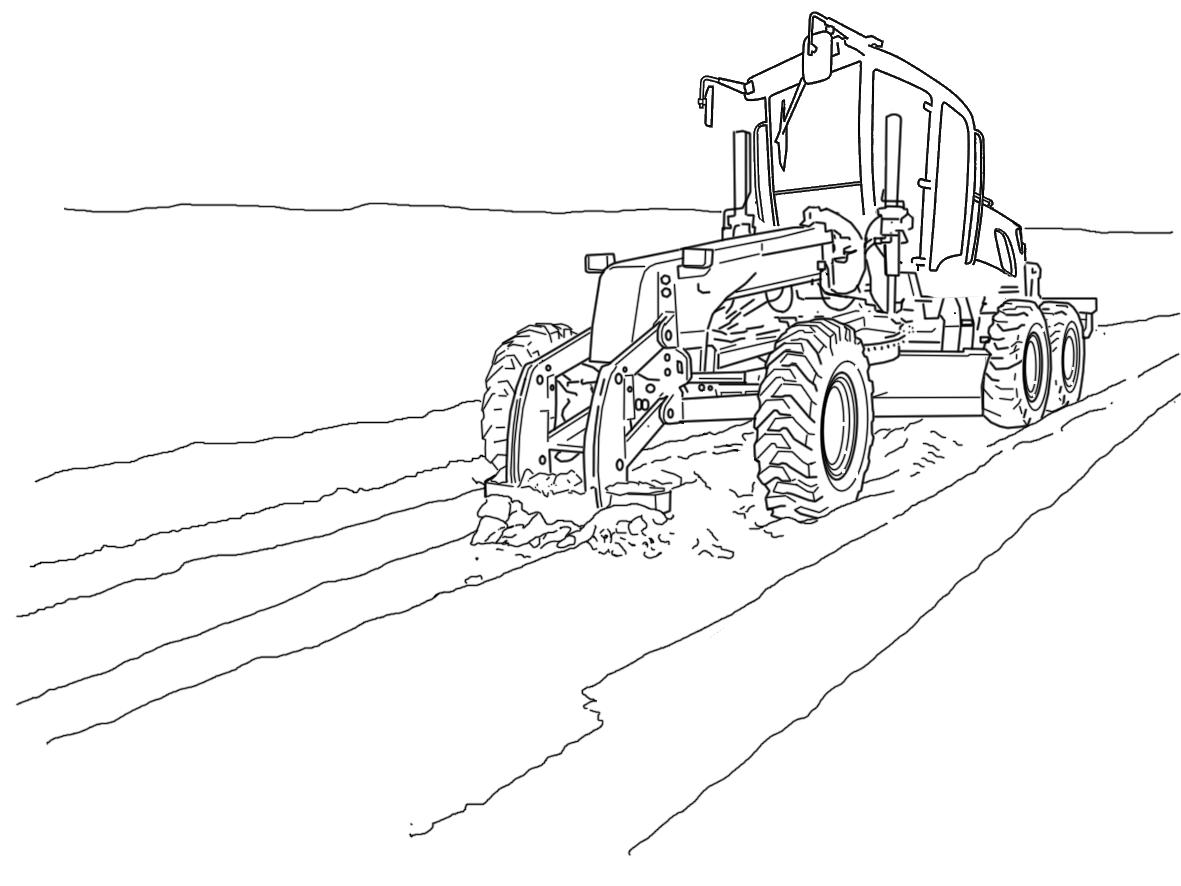
Scarifing
To scarify a surface it is advised to use all the teeth with less penetration than to use less teeth with deeper penetration. It is advantageous to break the surface material into smaller bits. When the scarifier is used in crowded areas, pay attention to the shallow sewers, galleries, and other utilities. Use the lowest speed (1st or 2nd gear) with high engine speed to maintain better control of the grader and to provide good breaking of surface material. The scarifier teeth must be in good condition for best results. Never back drag the scarifier teeth. This can seriously damage the tool bar.
2
1
1. REAR SCARIFIER
When operating a grader and a sharp non articulated turn is to be made, reduce speed and lean the front wheels in the direction of the turn. After completing the turn, straighten the front wheels to the normal position and resume normal speed. When roading a grader from one location to another, carry the moldboard within the wheel width and raised as high as possible to prevent accidents.
2. FRONT SCARIFIER
When driving or operating the grader in traffic always set the hand throttle at low idle. Select the gear range desired, then use the accelerator/decelerator pedal to change the machine’s road speed. The disengagement device must be in off position so that the engine runs as a retarder. Be sure that the engine speed control system is functioning properly, so that the engine speed returns to idle when the operator takes his foot from the accelerator/decelerator pedal. When roading the grader, obey all traffic regulations and be aware of other traffic. Be prepared for any emergency. If the grader is used in congested areas or roads, put adequate warning signs to prevent accidents. Always be aware of other traffic, especially before change of direction or working across traffic flow.
stopping and Parking the Grader
Position the grader in the desired parking area. Position the moldboard with the ends of the blade within the wheel width and lower the moldboard to the ground. Place the transmission forward/reverse lever in neutral and apply the parking brake. Before stopping engine, allow engine to run at 1/4 throttle for 3 to 4 minutes to gradually cool the engine. Then move the throttle lever to idle position and put the ignition key on the OFF position. Remove the key and apply the parking / emergency brake. Check the ROPS mounting bolts after the first 50 hours of operation, and thereafter periodically. The machine’s cooling system is filled at the factory with a 50/50 mixture of water and AKCELA PREMIUM ANTI FREEZE. The AKCELA PREMIUM ANTI FREEZE solution protects the engine to -37°C (-34°F). It is not necessary to drain this solution before placing the unit in service.
Hot Weather
To prevent damage to the machine: 1. Keep the cooling coolant correct level in the reservoir and in the radiator. 2. Test the expansion tank cap before the climate becomes too hot. Replace the radiator cap, if necessary. 3. Clean all dirt and debris from the cooling system and engine area. 4. Use lubricants of the correct viscosity. 5. Use the correct solution of AKCELA PREMIUM ANTI
FREEZE and water in the cooling system. 6. Use lubricants with recommended viscosity..
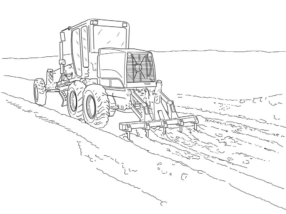
Operating Tips
Articulated graders can be operated with the frame ARTICULATED OR OFF SET (CRAB).
ARTICULATED
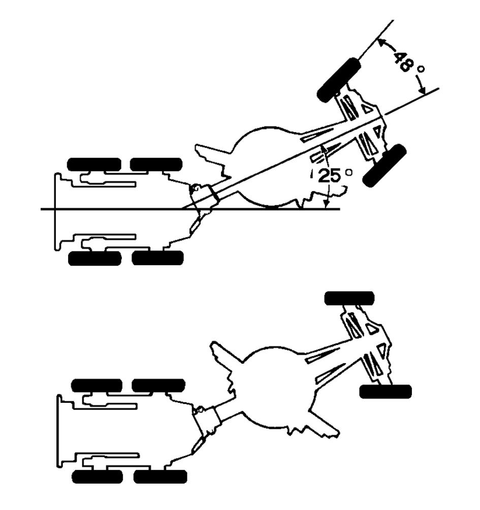
OFF-SET
NON ARTICULATED frame is normally used for grading large areas and for road maintenance and conservation. With the frame ARTICULATED, the turning radius is reduced, making machine control easier in restricted areas. In addition, a more precise control of material spreading is permitted.
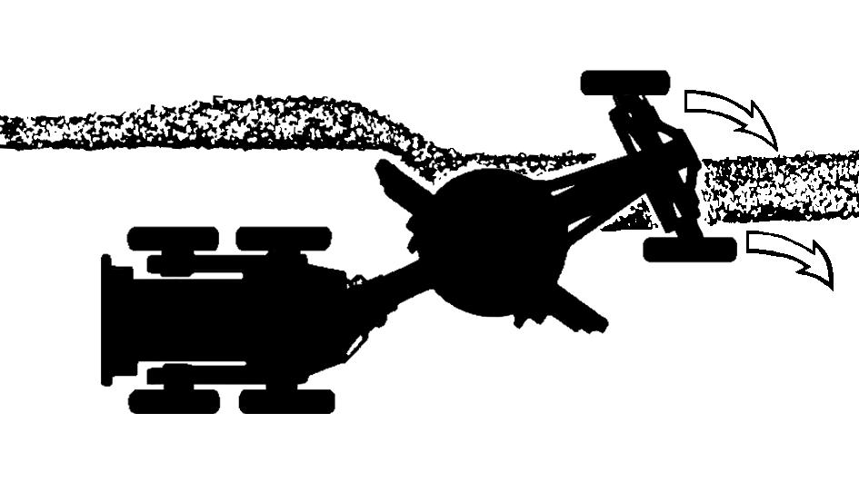
The OFFSET position permits the operator to maintain the machine on firm ground when working in ditches, and reduce the number of passes necessary to spread material. This permits a better weight concentration, behind the blade in severe operation conditions. Although the grader permits the circle turn 360°, most of the grading operations are done with the blade between 15° and 45° in relation to the work direction. Increasing the angle of the blade reduces the side movement of the material cut by the blade. However this permits deeper cuts and more “severe” grading. The change of the attack angle, blade pitch is also very important for productivity. Tilting the moldboard towards the front, eases the rolling of the cutting material and allows still better spreading and compaction of the material. Tilting the moldboard towards the rear, permits higher cutting action of the moldboard, but reduces the material rolling along the moldboard. The blade with the involute “ROLL-AWAY” profile maintains the capacity to roll material, with the top of the blade inclined to the rear. Changing blade angle while cutting, generates side forces on the machine. These forces should be compensated by leaning the front wheels and/or articulating the frame in the direction of the blade cutting forces.
1 2
1. 2. LEANED FRONT WHEELS ARTICULATED CHASSIS
The angle change is only recommended during the cutting, for machines equipped with phenolic resin plates on the circle supports, in order to reduce the friction and wear of the circle table.


