1 minute read
Fuel system
GENERAL INFORMATION 1-3
4. When the same servicing operation is applicable to several different units, the manual will direct you to the appropriate page. 5. For the sake of brevity, self-explanatory removal and installation procedures are omitted. More complex procedures are covered in detail. 6. Each service operation section in this Service Manual begins with an exploded view of the applicable area. A brief explanation of the notation used follows.
Parts marked with an asterisk (*) are included in the repair kit.
Parts within a square frame are to be removed and installed as a single unit. All parts within an irregularly shaped frame form a single assembly. They are considered to be a “major component”. Individual parts within the irregularly shaped frame are considered to be “minor components”.
The number indicates the service operation sequence. Removal of unnumbered parts is unnecessary unless replacement is required.
The “* Repair Kit” indicates that a repair kit is available.
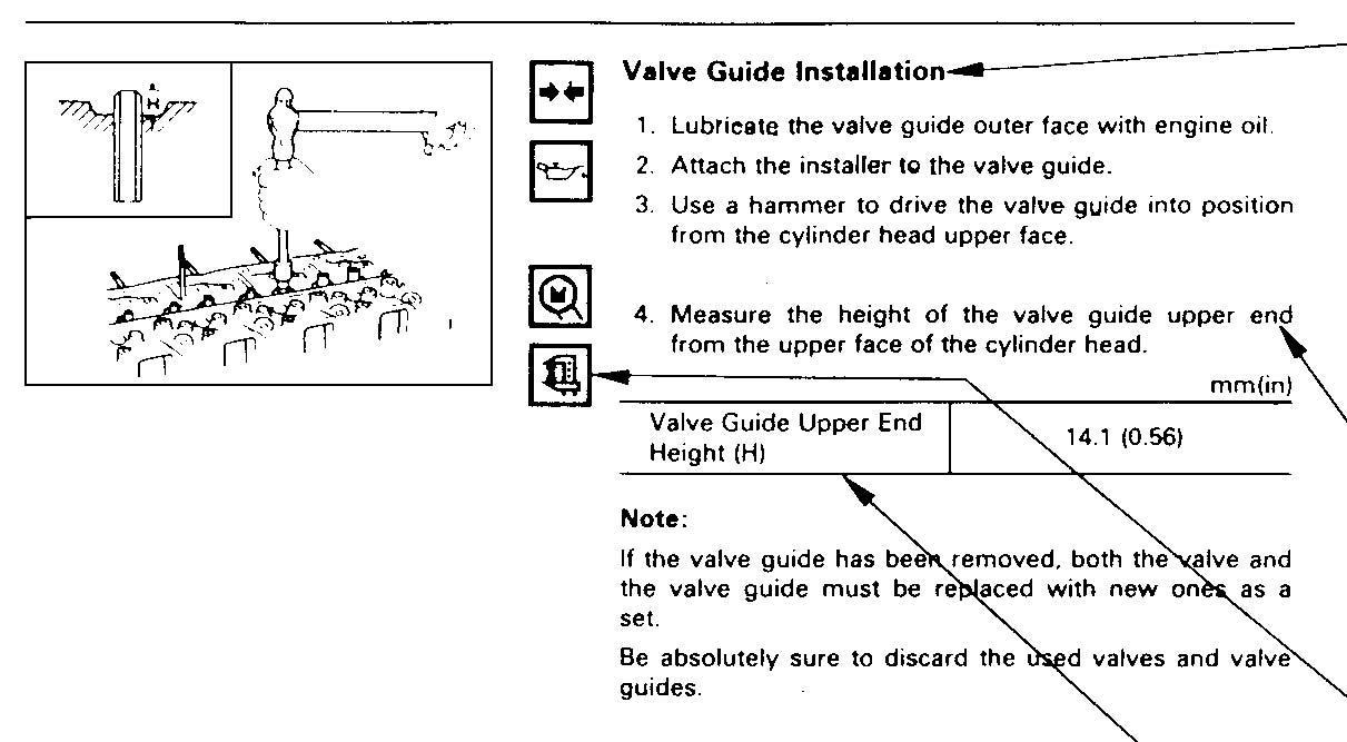
The parts listed under “Reassembly Steps” or “Installation Steps” are in the service operation sequence. The removal or installation of parts marked with a triangle ( ) is an important operation. Detailed information is given in the text.

This is the item shown in the illustration. It is marked with a triangle ( ) on the Major Components page. Letters and numbers contained in a circle refer to the illustration.
Symbols indicate the type of service operation or step to be performed. A detailed explanation of these symbols follows. Service data and specifications are given in this table.
8. The following symbols appear throughout this Service Manual. They indicate the type of service operation or step to perform.


