18 minute read
MAINTENANCE SAFETY


Instructions are necessary before operating or servicing machine. Read Operation & Maintenance Manual, Handbook and signs (decals) on machine. Follow warnings and instructions in the manuals when making repairs, adjustments or servicing. Check for correct function after adjustments, repairs or service. Failure to follow instructions can cause injury or death.
Safety Alert Symbol:This symbol is used for important safety messages. When you see this symbol, follow the safety message to avoid personal injury or death.
Correct
Correct
Correct
Never service the Bobcat Hydraulic Excavator without instructions.
Use the correct procedure to lift and support the excavator. Always lift the blade fully before installing jackstands.
Cleaning and maintenance are required daily.
Wrong Wrong Wrong
Have good ventilation when welding or grinding painted parts. Wear dust mask when grinding painted parts. Toxic dust and gas can be produced.
Vent exhaust to outside when engine must be run for service. Exhaust system must be tightly sealed. Exhaust fumes can kill without warning.
Always lower the bucket and blade to the ground before doing any maintenance. Never modify equipment or add attachments not approved by Melroe Company.
Wrong Wrong Wrong
Stop, cool and clean engine of flammable materials before checking fluid. Never service or adjust machine with the engine running unless instructed to do so in the manual. Avoid contact with leaking hydraulic fluid or diesel fuel under pressure. It can penetrate the skin or eyes. Never fill fuel tank with engine running, while smoking or when near open flame.
Keep body, jewelry and clothing away from moving parts, electrical contacts, hot parts and exhaust.
Wear eye protection to guard from battery acid, compressed springs, fluids under pressure and flying debris when engines are running or tools are used. Use eye protection approved for type of welding. Keep rear door closed except for service. Close and latch door before operating the excavator.
Lead–acid batteries produce flammable and explosive gases. Keep arcs, sparks, flames and lighted tobacco away from batteries.
Batteries contain acid which burns eyes or skin on contact. Wear protective clothing. If acid contacts body, flush well with water. For eye contact flush well and get immediate medical attention.
Maintenance procedures which are given in the Operation & Maintenance Manual can be performed by the owner/operator without any specific technical training. Maintenance procedures which arenot in the Operation & Maintenance Manual must be performed ONLY BY QUALIFIED BOBCAT SERVICE PERSONNEL. Always use genuine Bobcat replacement parts.
Service Schedule
Maintenance work must be done at regular intervals. Failure to do so will result in excessive wear and early failures. The service schedule is a guide for correct maintenance of the Hydraulic Excavator.
Instructions are necessary before operating or servicing machine. Read Operation & Maintenance Manual, Handbook and signs (decals) on machine. Follow warnings and instructions in the manuals when making repairs, adjustments or servicing. Check for correct function after adjustments, repairs or service. Failure to follow instructions can cause injury or death. W–2003–0797
Engine Air CleanerCheck & empty dust cap as required.
Engine Oil Check the engine oil and add as needed.
Engine Coolant SystemCheck radiator coolant level.
Indicator Lights Check for correct operation.
Operator Canopy Check the fastening bolts, nuts & condition of cab.
Seat Belt Check the condition & that fasteners are tight.
Safety Signs (Decals)Check for damaged signs (decals); replace as needed.
Tracks Check & adjust tension.
Hydraulic ReservoirCheck fluid level.
All Machinery Pivot PinsLubricate 22 grease fittings.
Fuel Tank/Fuel FilterDrain water and sediment from fuel tank/filter.
Swing Circle Lubricate 2 grease fittings.
Swing Pinion Lubricate one grease fitting.
Engine Oil & Filter Replace oil & filter element.
Alternator Belt Check & adjust tension.
Hydraulic Filter Replace filter element.
Fuel Filters Replace filter elements.
Battery Check & clean cable ends & check electrolyte level.
Air Cleaner Replace the filter element.
Cooling System Clean the radiator fins.
Alternator & StarterCheck the condition.
Engine Valve ClearanceCheck & adjust valve clearance.
Cooling System Drain, flush & add new coolant to the cooling system.
Hydraulic Tank Change the fluid and change the fill neck strainer.
Case Drain Return ScreenClean the screen with solvent (if equipped).
Final Drive Case Change the gear lube.
After the first 250 hours of machine operation do the following:
*Change the oil in the final drive case.
*Check and adjust engine valve clearance.
Avoid Injury Or Death
Never service or adjust the machine when the engine is running unless instructed to do so in this manual.
W–2012–1285
Keep the engine cover closed when operating the machine.

W–2141–0189
Open the engine cover to service the engine. Pull on the latch and lift the engine cover up until it is fully raised[A].
Air Cleaner Service
See the SERVICE SCHEDULE Page 25 for the correct service interval.
Service the air cleaner as follows:
Daily Check
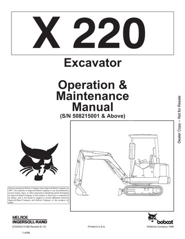
Loosen the clamp on the air cleaner [B].

Remove the cover (Item 1) [C] and the dust cup (Item 2) [C]
Empty dust cup. Visually inspect the filter element. Do not remove element unless plugged and replacement is necessary.
Filter Replacement
Remove the wing nut (Item 3) [C].
Remove the filter element [D]
Check the air cleaner housing for damage.
Wipe the canister and the seal surface clean with a clean cloth. Do Not use compressed air.
Check the seal (Item 1) [D] for damage. Do not use an air filter element with a damaged seal.
Install a new air filter element. Install and tighten thewing nut.

Install the dust cup and cover so the arrow points up.
Check that all the air cleaner hose clamps are tight.
Fuel System
Fuel Specification
Use only clean, high quality diesel fuel, Grade No. 2 or Grade No. 1.
The following is suggested blending guideline which should prevent fuel gelling problems.
Temp.
+15o(9o) 100% 0%
Down to –20o (–29o)50% 50%
For local recommendations, the operator can contact his fuel supplier.
Stop and cool the engine before adding fuel. NO SMOKING! Failure to obey warnings can cause an explosion or fire.
W–2063–0887
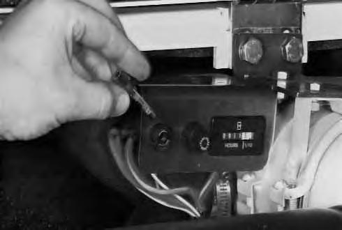
Filling The Fuel Tank
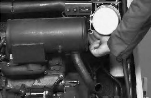
The fuel level in the tank is indicated by the fuel gauge (Item 1) [A] when the ignition key is in the ON position.
NOTE:When the fuel level reaches the 1/8 fuel setting, the low fuel light (Item 2) [A] will come ON to alert the operator of this condition.
Use the key to unlock the fuel fill cap [B]

Turn the fill cap to remove it.
Use a clean, approved safety container to add fuel to the tank.
Add fuel only in an area that has a free movement of air and no open flames or sparks. NO SMOKING!
Always clean up spilled fuel or oil. Keep heat, flames, sparks or lighted tobacco away from fuel and oil. Failure to use care around combustibles can cause explosion or fire which can result in injury or death.
W–2103–1285
A P–00805 2 1 Operation & Maintenance Manual –27–220 (S/N 508215001 & Above) Excavator B P–00810
FUEL SYSTEM (Cont’d)
See the SERVICE SCHEDULE Page 25 for the correct service interval.
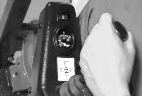
To remove the water and sediment from the fuel tank, remove the fuel hose at the fuel filter inlet elbow[A]. Insert the end of the fuel hose into an approved container and drain.

NOTE:If fuel will not drain, squeeze the primer bulb to start the fuel to flow.
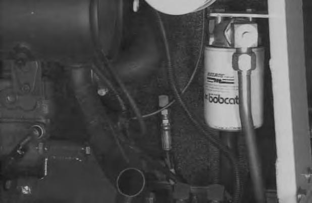
Fuel Filters
See the SERVICE SCHEDULE Page 25 for the correct service interval.
To remove water from filter, open the drain valve (Item 1) [B] at the bottom of the fuel filter.
Use a filter wrench to remove the final fuel filter [B].
Replace the element and hand tighten only.
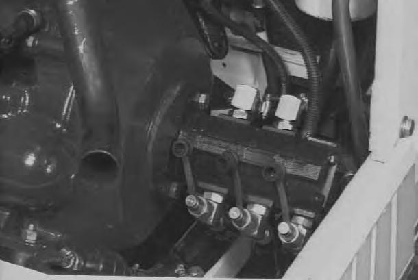
Removing Air From The Fuel System
After replacing the fuel filter or after running out of fuel, air must be removed from the fuel system before starting the engine.
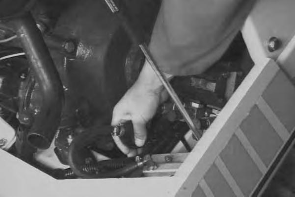
Open the vent screw (Item 1) [C] on the injection pump. Open the bleed screw on the top of the fuel filter housing (Item 1) [A]
Squeeze the primer bulb (Item 1) [D] to fill the filter.
When fuel, free of air bubbles, comes from the filter housing, close the bleed screw.
Leave the vent on the injection pump slightly open.
Start the engine. When the engine runs smoothly, close the vent screw on the injection pump.
NOTE:If engine fails to start after above procedure is performed, it will be necessary to bleed the injector lines, do the following:
– Loosen the three (3) injector line lock nuts, one turn.
– While cranking engine, as fuel emerges from injector lines, slowly tighten the injector line lock nuts.

Engine Lubrication System

Check the engine oil every day. Stop the engine. Open the engine cover.

Remove the dipstick [A].
Keep the oil level between the marks on the dipstick. Use a good quality motor oil that meets the correct API Service Classification of CD or better. (See FUEL, COOLANT AND LUBRICATION Chart Page 48.)
Engine Oil And Filter Replacement
See the SERVICE SCHEDULE Page 25 for the correct service interval.
Use the following procedure to change the oil and filter: Run the engine until it is at operating temperature.
Turn the upperstructure so there is clearance for the engine oil drain plug. Stop the engine.
Remove the drain plug (Item 1) [B]. Drain the oil into a container.
Remove the oil filter (Item 1) [C], using a filter wrench. Clean the filter housing surface. Put clean oil on the filter gasket. Install the new filter and hand tighten only.
Install and tighten the oil drain plug.
Clean the area around the dipstick and remove the dipstick [A]
Remove the dipstick tube cap [D]. Use a funnel and put 4.5 quarts (4,3 L) of oil into the engine. (See FUEL, COOLANT AND LUBRICATION Chart Page 48).
Start the engine and let it run for several minutes. Stop the engine. Check for leaks at the oil filter and the oil drain plug.
Check the oil level and add oil as needed if it is not at the top mark on the dipstick.

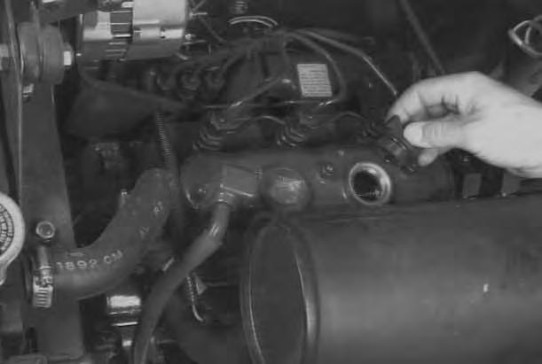
Cooling System
Coolant Level
When the engine is cool, remove the radiator cap [A].
The coolant level must be 3/4–1 inch (19–25 mm) below the filler neck at the radiator.
If the coolant level is low, add premixed coolant (50% water and 50% ethylene glycol) to the radiator.
Coolant Replacement
Turn the upperstructure so there is access to the engine and radiator from between the tracks. Stop the engine.
When the engine is cool, loosen and remove the radiator cap [A]
Open the radiator drain valve (Item 1) [B]


Drain all the coolant into a container.
When all the coolant is removed, close the drain valve.
Propylene Glycol
Pre–mix 50% water and 50% ethylene glycol in a separate container. Fill the radiator with the pre–mixed coolant until it is full.
Run the engine at idle speed for about 5–10 minutes to remove the air from the cooling system (leave the radiator cap off during this operation).
Stop the engine. Check the coolant level and add as needed to bring it 3/4–1 inch (19–25 mm) below the filler neck. Install the radiator cap and tighten.
Wear safety glasses to prevent eye injury when any of the following conditions exist:
• When fluids are under pressure.
• Flying debris or loose material is present.
• Engine is running.
• Tools are being used.
W–2019–1285
Alternator Belt Adjustment

To adjust the belt tension, use the following procedure: Stop the engine. Open the engine cover.

The belt should deflect about 5/8 inch (16 mm) when pressed between the water pump pulley and crankshaft pulley with approximately 22 lbs. (10 kg) pressure [A]
If the tension is not correct, loosen the alternator mounting bolt.
Loosen the adjustment bolt [B]
Move the alternator until the belt tension is correct.
Tighten the adjustment bolt and alternator mounting bolt. Replace the belt if it has stretched or there are cracks in the belt. Check the pulley grooves, make sure the belt is not in contact with the bottom of the groove in the pulleys.
Electrical System
The excavator has a 12 volt, negative ground charging system.
Fuses
The following fuses protect these circuits from overload:
1.25 amp: This fuse protects the engine starting circuit, gauge functions, horn, audible alarm and control console microswitches.
2.25 amp: This fuse protects the cab heater (if equipped) and the accessories.

Replace all fuses with the same type and capacity.
NOTE:Before replacing any fuse, find and fix the problem that caused the circuit overload. Make sure the key switch is in the OFF position before replacing the fuse.
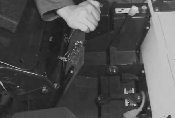
Service The Electrical System
Slide the seat forward.
Remove the pins from the seat plate [B].


Raise the operator cab [C]
The battery cables must be clean and tight [D]. Remove any acid or corrosion from the battery and cables using a sodium bicarbonate and water solution. Cover the battery terminals and cable ends with battery saver grease.
Check for broken or loose connections.
With factory equipped battery, no maintenance is needed as this is a maintenance free battery.
If the machine has had a Melroe parts replacement battery installed, check the electrolyte level in the battery.
If it is lower than 1/2 inch (13 mm) above the plates, add distilled water only.
Batteries contain acid which burns eyes and skin on contact. Wear goggles, protective clothing and rubber gloves to keep acid off body.
In case of acid contact, wash immediately with water. In case of eye contact get prompt medical attention and wash eye with clean, cool water for at least 15 minutes.
If electrolyte is taken internally drink large quantities of water or milk! DO NOT induce vomiting. Get prompt medical attention.
W–2065–1296
ELECTRICAL SYSTEM (Cont’d)
Using A Booster Battery (Jump Starting)
If it is necessary to use a booster battery to start the engine, BE CAREFUL!
Make sure the swing lock is in the engaged position. The key switch must be in the OFF position.
The booster battery must be 12 volt.
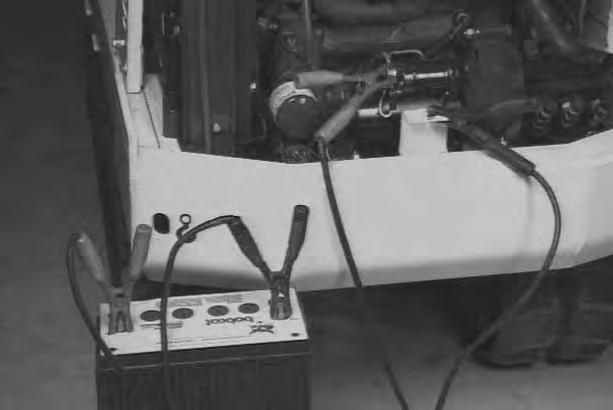
Open the engine cover [A].
Connect the end of the first cable to the positive (+) terminal of the booster battery. Connect the other end of the same cable to the starter positive (+) battery cable terminal (Item 1) [B] & [C].
Connect the end of the second cable to the negative (–) terminal of the booster battery. Connect the other end of the same cable to the frame (Item 2) [B] & [C]
NOTE:See Cold Temperature Starting Procedure, Page 15.
Start the engine. After the engine is running, remove the negative (–) cable (Item 2) [B] connected to the frame first. Disconnect the cable from the starter terminal (Item 1) [B] & [C]
Keep arcs, sparks, flames and lighted tobacco away from batteries. When jumping from booster battery make final connection (negative) at engine frame.
Do not jump start or charge a frozen or damaged battery. Warm battery to 60°F. (16°C.) before connecting to a charger. Unplug charger before connecting or disconnecting cables to battery. Never lean over battery while boosting, testing or charging.
Battery gas can explode and cause serious injury.
W–2066–1296
Damage to the alternator can occur if:
• Engine is operated with battery cables disconnected.
• Battery cables are connected when using a fast charger or when welding on the loader (Remove both cables from the battery).
• Extra battery cables (booster cables) are connected wrong.
I–2023–1285
When jump starting from a second machine:
If ‘‘jump starting’’ the excavator from a battery installed in a second machine, make sure that the second machine is NOT running while using the glow plugs. High voltage spikes from a running machine can burn out the glow plugs.
I–2060–0195
ELECTRICAL SYSTEM (Cont’d) Removal And Installation Of The Battery
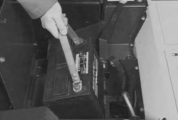

Move the operator seat to the full forward locked position. Remove the two retaining pins from the seat plate [A].

Tilt the operator seat forward [B].
Disconnect the negative (–) cable (Item 1) [C] first.
Disconnect the positive (+) cable (Item 2) [C].
Remove the two bolts (item 3) [C] and remove the holddown clamp (Item 4) [C].
Remove the battery from the compartment [D].
Always clean the terminal and the cable ends, even when installing a new battery.
Install the battery. Install the holddown clamp and the two bolts.
NOTE:Do not touch any metal to the battery terminals.
Connect the battery cables. Connect the negative (–) cable (Item 1) [C] last to prevent sparks at the terminal.
Batteries contain acid which burns eyes and skin on contact. Wear goggles, protective clothing and rubber gloves to keep acid off body.
In case of acid contact, wash immediately with water. In case of eye contact get prompt medical attention and wash eye with clean, cool water for at least 15 minutes.
If electrolyte is taken internally drink large quantities of water or milk! DO NOT induce vomiting. Get prompt medical attention.
W–2065–1296
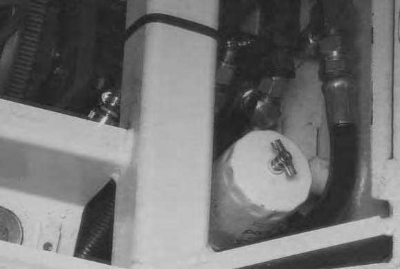
HYDRAULIC SYSTEM Checking And Adding Fluid
Prior to checking the hydraulic fluid level, retract the arm and bucket cylinder, put the bucket on the ground and raise the blade.
Put the machine on a level surface. Retract the arm and bucket cylinders, put the bucket on the ground and raise the blade. Stop the engine. The hydraulic fluid level must be visible in the center of the sight gauge (Item 1) [A]


If the fluid level is not correct, remove the reservoir cap [B]
Check the condition of the fill strainer [C]. The strainer must be installed in the fill neck when adding oil.
Add the correct fluid to the reservoir until it is in the center of the sight gauge [A]. (See Fuel, Coolant and Lubricants Chart, Page 48.)
Install the reservoir cap.
HYDRAULIC SYSTEM (Cont’d)
Diagnostic Couplers
Diagnostic couplers are located at each section of the hydraulic pump (Item 1) [A]
The couplers can be used to check circuit pressures. (Refer to the Service Manual.)
Prior to checking the hydraulic fluid level, retract the arm and bucket cylinder, put the bucket on the ground and raise the blade.
Replacement of the Hydraulic Filter
See the SERVICE SCHEDULE Page 25 for the correct service interval.
Open the engine cover.
Remove the filter element (Item 1) [B]
Clean the housing where the filter gasket makes contact. Put clean hydraulic fluid on the gasket. Install the new filter element and hand tighten only.
Start the engine. Run the machine through the hydraulic functions. Stop the engine. Check the fluid level at the reservoir and add as needed. Check the filter area for leaks.
Hydraulic Reservoir
Replacement Of The Hydraulic Fluid
See the SERVICE SCHEDULE Page 25 for the correct service interval.
Move the upperstructure so there is clearance for the reservoir drain between the tracks.
Retract the arm and bucket cylinders, lower the bucketto the ground. Stop the engine.
Remove the hydraulic filter element [B]

Remove the drain plug (Item 1)[C] from the bottom of the reservoir.
Drain the fluid into a container.
Install the drain plug.
Install the filter. (See information above.)
Add the correct fluid to the reservoir untilit is visible in the sight gauge (approximately 3.75 gals. [14,2 L.] to fill only the reservoir). (See Fuel, Coolant and Lubricants Chart Page 48.)
Run the machine through the hydraulic functions. Stop the engine. Check the fluid level and add as needed.
Lubrication Of The Hydraulic Excavator
Lubricate the Hydraulic Excavator as specified in the SERVICE SCHEDULE Page 25 for the bestperformance of the machine.

Record the operating hours each time you lubricate the Hydraulic Excavator.
Always use a good quality lithium based multi–purpose grease when lubricating the machine. Apply the lubricant until extra grease shows.
Ref.Description (# of Fittings)
1.Blade Cylinder Rod End, every 8–10 hours (1)[A]
2.Blade Pivots, every 8–10 hours (2) [A]
3.Blade Cylinder Base End, every 8–10hours (1) [A].
4.Boom Swing Cylinder Rod End, every 8–10hours (1) [B].
5.Boom Cylinder Base End, every 8–10 hours (1) [B].
6.Boom Base Pivot, every 8–10 hours (1) [B]
7.Swing Circle Pinion, every 50 hours (1)[B]. Install 4 pumps of grease from a grease gun into the grease fitting. Rotate the upperstructure 180o and install 4 more pumps ofgrease into the grease fitting.

8.Boom Swing Bracket Pivot, every 8–10 hours (2) [C]
9.Frame Swing Bracket Pivot, every 8–10 hours (1) [C]

10.Boom Cylinder Rod End, every 8–10 hours (1)[D]
11.Arm Cylinder Base End, every 8–10 hours (1)[D]
12.Arm Cylinder Rod End, every 8–10 hours (1) [D]
13.Arm Base Pivot, every 8–10 hours (1) [D]
14.Bucket Cylinder Base End, every 8–10 hours (1) [D].
LUBRICATION OF THE HYDRAULIC EXCAVATOR (Cont’d)
Ref.Description (# of Fittings)
15.Bucket Cylinder Rod End, every 8–10 hours (1) [A]
16.Bucket Link Pivots, every 8–10 hours (2) [A]
17.Bucket Pivots, every 8–10 hours (3) [A].
18.Boom Swing Cylinder Base End, every 8–10 hours (1) [B].
NOTE: Access to the grease fitting is from under the upperstructure, right side.

19.Swing Circle Ball Bearing, every 50 hours (2) [C].
NOTE:Do not over grease the swing circle or damage to the seal could result. Install 4 to 5 pumps of grease from a grease gun into each of the 2 grease fittings. Rotate the upperstructure 90o and install 4 to 5 pumps of grease into each of the 2 grease fittings.
Final Drive Case
Checking Oil Level
Put the machine on a level surface.
Position the plugs (Item 1) [A] parallel to the ground.
Remove one of the plugs (Item 1) [A]
Add gear lube through the hole if the gear lube level is below the hole. (See Fuel, Coolant and Lubricant Chart, Page 48.)

Install and tighten the plug.
Repeat the procedure for the other side.
Replacing Final Drive Case Oil
See the SERVICE SCHEDULE Page 25 for correct service interval.
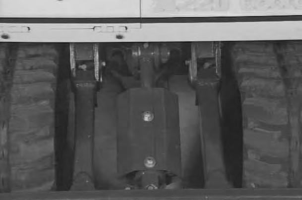
Put the machine on a level surface with the plugs positioned as shown in figure [B].
Remove the bottom plug (Item 1) [B] and the top plug (Item 2) [B].
After all the gear lube is removed, install and tighten the bottom plug.
Add .3 quarts (0,3 L) of gear lube to the top plug hole. Install the plug.
Move the excavator until the plugs are positioned parallel to the ground [A]

Use the same procedure as for Checking Oil Level, (See information above) add additional oil as needed.
Repeat the procedure for the other side.
Track Tension
NOTE:The wear of the parts on the undercarriage vary with the working conditions and the different types of soil conditions. It is necessary to inspect track tension to maintain the correct tension. (See SERVICE SCHEDULE Page 25 for the correct service interval.)

Adjustment
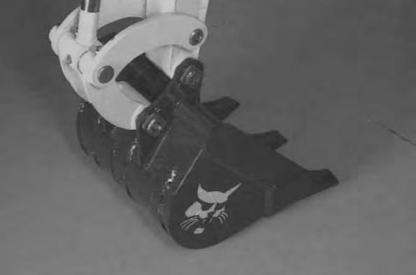
Raise one side of the machine (approximately 4 inches) using the boom and arm as shown in [A].

Raise the blade fully and install jackstands under the blade and the track frame. Operate the boom until all machine weight is on the jackstands.
Stop the engine.
Avoid Injury
Keep fingers and hands out of pinch points when checking the track tension.
W–2142–0189
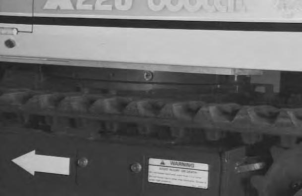
Measure the distance between the frame and the top of the track. If the distance is between 2.25–2.50 inch (57–63 mm), the track tension is correct [B].
If not, loosen one bolt and remove the other bolt from the cover [C]
Add grease to the fitting(Item 1) [D] until the track tension is correct.

If track tension is too tight, decrease the track tension pressure by loosening the bleed screw (Item 2) [D] (maximum of 1 turn) and allow grease to flow out of the bleed screw. When the tension is correct, tighten the bleed screw.
Repeat the procedure for the other side.
If the track tension is still loose after adjusting to theabove mentioned limit, it indicates the track is worn. See your dealer for repairs.
Avoid Injury
Do not loosen the grease fitting more than one complete rotation. Also, be careful not to loosen any part other than the grease fitting. If the grease fitting or any part is loosened too much, it can fly off under high pressure. If the grease does not ooze smoothly, try moving the machine back and forth for a short distance.
W–2143–0189
Joystick Control Change
ISO To Standard Control Pattern
To change from ISO to STANDARD joystick controls, do the following procedure:
Open the tool box door.
Remove the hose cover plate.
Remove the bottom plate from the tool box.
Mark and remove hoses (Items 1, 2, 3 & 4) [A] from the bulkhead elbows.
Install the hoses onto the new locations as shown (Items 1, 2, 3 & 4) [B]
Install new decals (P/N 6587427) onto the right hand console and (P/N 6587428) onto the left hand console.
After exchange of the hoses, the right joystick will now control arm (raise and lower) and the bucket (curl). The left joystick will control the boom (raise andlower) and the upperstructure (swing).
See Service Manual for additional information.
Standard To ISO Control Pattern
To change from STANDARD to ISO joystick controls, do the following procedure:
Open the tool box door.
Remove the hose cover plate.
Remove the bottom plate from the tool box.
Mark and remove hoses (Items 1, 2, 3 & 4) [C] from the bulkhead elbows.

Install the hoses onto the new locations as shown (Items 1, 2, 3 & 4) [D].
Install new decals (P/N 6587425) onto the right hand console and (P/N 6587426) onto the left hand console.
After exchange of the hoses, the right joystick will now control boom (raise and lower) and the bucket (curl). The left joystick will control the arm (raise and lower) and the upperstructure (swing).
See Service Manual for additional information.
HYDRAULIC EXCAVATOR
SPECIFICATIONS
A – 102.7 (2609)
B – 38.62 (981)
C – 86.8 (3205)
D – 28.75 (730)
E – 9.84 (250)
F – 102.7 (2609)
G – 10.4 (264)
H – 43.8 (1112)
I – 58.3 (1480)
J – 35.7 (907)
K – 17.15 (435)
L – 45.8 (1164)
M – 1.02 (26)
N – 20.10 (511)
O – 23.62 (600)
All dimensions are shown in inches. Respective metric dimensions are given in millimeters enclosed by parentheses.
Where applicable, specification conform to SAE or ISO standards and are subject to change without notice.
Hydraulic Excavator Specifications
Operating Weight (Includes 20” Bucket) ROPS Canopy – 3250 Lbs. (1474 kg) km/hr.)
CONTROLS
Vehicle Two Hand or Foot Levers
Excavator Two pilot–operated joysticks control boom, bucket, arm and cab swing. Right foot pedal controls boom swing. Left foot pedal controls auxiliary hydraulics. The blade is controlled by a separate lever.
ENGINE
Make Kubota Model D–750 BW–Clark2
(10,1 Kw) @ 2500 RPM Maximum
3–Spool, parallel Type, Open center (Blade, Swing & Boom Swing);
6–Spool, Parallel Type, Open Center (R.H. Travel, Boom, Arm, Bucket & Blade, L.H. Travel)
Design Undercarriage. Sealed Track Rollers with Reinforced Box–Section Track Roller Frame. Grease Type Track Adjusters with Shock Absorbing Recoil Springs.
FUEL, COOLANT AND LUBRICANTS
Use this chart for correct selection of Fuel, Coolant and Lubricants.
* If Bobcat fluid (P/N 6563328) is not available, use Engine Oil SAE 10W–30/10W–40, Class SE, or better.
Engine Oil Specifications
Description
When fuel sulphur content is less than 0.5% change the engine oil and filter as shown in theSERVICE SCHEDULE Page 25.
Change engine oil and filter according to the following chart if fuel sulphur content is above 0.5%.
Fuel SulphurChange Interval Of ContentEngine & Oil Filter
0.5 to 1.0%1/2 of Regular Interval Above 1.0%1/4 of Regular Interval