19 minute read
MONITORING THE DISPLAY PANELS


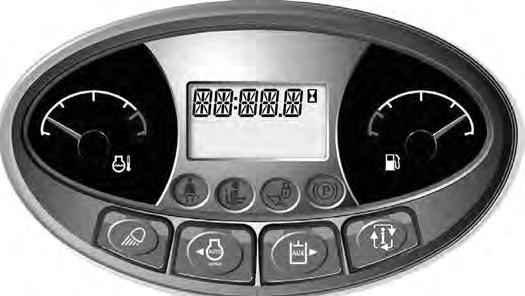
Instrument Panel
Figure 100
Frequently monitor the temperature and fuel gauges [Figure 100].
After the engine is running, frequently monitor the instrument panel [Figure 100] for machine condition.

The associated icon is displayed if there is an error condition.
EXAMPLE: Engine Coolant Temperature is High.
The Engine Coolant Temperature icon (Item 1) [Figure 100] is ON.
Press the Information button (Item 2) (Standard Panel) or press a scroll button (Item 3) [Figure 100] (Deluxe Panel) repeatedly to cycle the data display until the service code screen is displayed. One of the following SERVICE CODES is displayed.
• [M0810] Engine Coolant Temperature Too High
• [M0811] Engine Coolant Temperature Extremely High
Find the cause of the service code and correct before operating the excavator again. (See DIAGNOSTIC SERVICE CODES on Page 185.)
NOTE:The optional Deluxe Instrumentation Panel offers an additional view of service codes that includes a brief description. (See DIAGNOSTIC SERVICE CODES on Page 185.)
Warning And Shutdown
When a WARNING condition exists; the associated icon light is ON and the alarm sounds 3 beeps. If this condition is allowed to continue, there may be damage to the engine or hydraulic systems.
When a SHUTDOWN condition exists; the associated icon light is ON and the alarm sounds continuously. The monitoring system will automatically stop the engine in 15 seconds. The engine can be restarted to move or relocate the excavator.
The SHUTDOWN feature is associated with the following icons:
General Warning
Engine Malfunction
Engine Coolant Temperature
STOPPING THE ENGINE AND LEAVING THE EXCAVATOR
Procedure
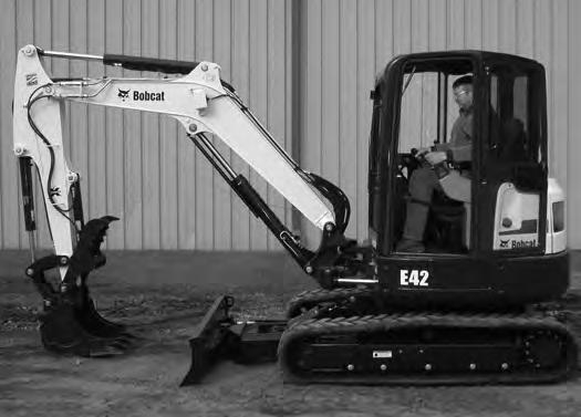
Stop the machine on level ground. Lower the work equipment and the blade to the ground [Figure 101]
Disconnect the seat belt. Remove the key from the switch (If Equipped) to prevent operation of machine by unauthorized personnel. Raise the control console and exit the machine.
Rotate the engine speed control dial (Item 1) [Figure 102] counterclockwise to low idle.
Run the engine at idle speed for about 5 minutes to allow it to cool.

Attachments
Installing And Removing The Attachment (Hydraulic X-Change)
Installation
NOTE: Installation and removal of the bucket is shown. The procedure is the same for other attachments. Disconnect any hydraulic lines that are operated by hydraulic power before removing any attachments (breaker, auger, etc.).
Warning
AVOID INJURY OR DEATH
Never use attachments or buckets which are not approved by Bobcat Company. Buckets and attachments for safe loads of specified densities are approved for each model. Unapproved attachments can cause injury or death.
W-2052-0907
Warning
AVOID INJURY OR DEATH
Both hydraulic pins must be fully extended through the attachment mounting holes. Failure to fully engage the hydraulic pins can allow attachment to come off.
W-2935-0512
Start the engine.
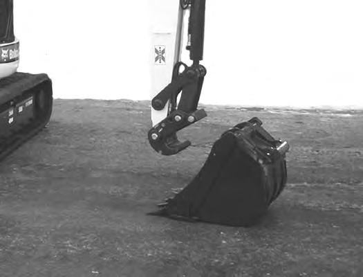
Swing the excavator arm fully to the left [Figure 104] (for better operator visibility when connecting attachments).


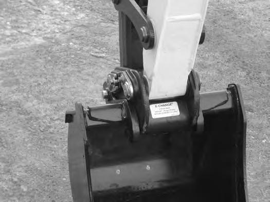
Raise the boom until the X-Change pins (Item 1) engage the attachment hooks (Item 2) [Figure 107] on the bucket.

ATTACHMENTS (CONT’D)
Installing And Removing The Attachment (Hydraulic X-Change) (Cont’d)
Installation (Cont’d)
Figure 108
109
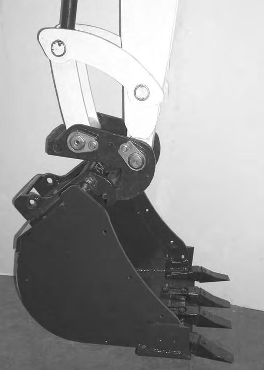
Raise the boom and extend (curl in) the bucket cylinder until the X-Change contacts the back of the attachment [Figure 108]
With the arm vertical, lower the boom until the hooks (Item 1) of the bucket disengage the X-Change pins (Item 2) and the plate (Item 3) [Figure 108] fully engages into the bucket crossmember.

Warning
Keep all bystanders 6 m (20 ft) away from equipment when operating. Contact with moving parts, a trench cave-in or flying objects can cause injury or death.
Press and hold the X-Change switch (Item 1) [Figure 109] to the left (OUT) and FULLY EXTEND the hydraulic pins.
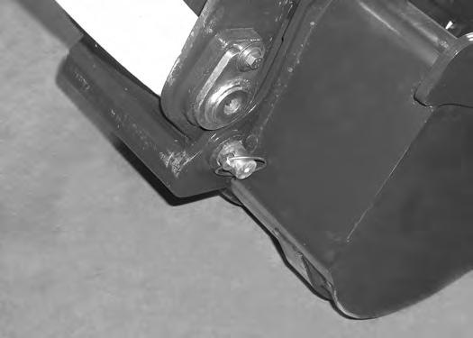
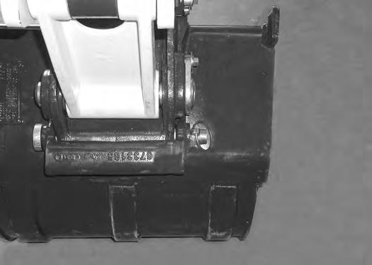
Check that both hydraulic pins (Item 1) [Figure 110] are fully engaged to secure the attachment.
Warning
AVOID INJURY OR DEATH
Both hydraulic pins must be fully extended through the attachment mounting holes. Failure to fully engage the hydraulic pins can allow attachment to come off.
ATTACHMENTS (CONT’D)
Installing And Removing The Attachment (Hydraulic X-Change) (Cont’d)
Removal
NOTE: Removal and installation of the bucket is shown. The procedure is the same for other attachments. Disconnect any hydraulic lines that are operated by hydraulic power before removing any attachments (breaker, auger, etc.).
Warning
Keep all bystanders 6 m (20 ft) away from equipment when operating. Contact with moving parts, a trench cave-in or flying objects can cause injury or death.
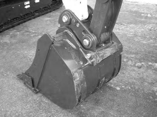
Raise the boom and retract the bucket cylinder until the X-Change pins (Item 1) engage the attachment hooks (Item 2) [Figure 113] on the bucket.
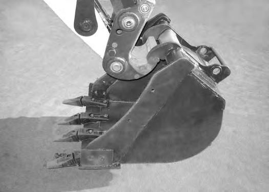
Park the excavator on a flat level surface. Put the attachment on the ground [Figure 111]
Fully retract the bucket cylinder (bucket dump).
Lower the boom and arm until the attachment is on the ground and the X-Change pins are disengaged from the attachment hooks.
Move the arm toward the excavator until the X-Change pins are clear of the attachment [Figure 114].

Press and hold the X-Change switch (Item 1) [Figure 112] on the left console to the right (IN) to FULLY RETRACT the hydraulic pins.
ATTACHMENTS (CONT’D)
Installing And Removing The Attachment (Pin Grabber Quick Coupler)

Installation
NOTE: Installation and removal of the bucket is shown. The procedure is the same for other attachments. Disconnect any hydraulic lines that are operated by hydraulic power before removing any attachments (breaker, auger, etc.).
Warning
AVOID INJURY OR DEATH
Never use attachments or buckets which are not approved by Bobcat Company. Buckets and attachments for safe loads of specified densities are approved for each model. Unapproved attachments can cause injury or death.

W-2052-0907
Start the engine. (See PRE-STARTING PROCEDURE on Page 60.)

Warning
AVOID INJURY OR DEATH
The quick coupler locking clasps must be fully engaged and locked to the attachment pins. Failure to fully engage the locking clasps can allow attachment to come off.
ATTACHMENTS (CONT’D)
Installing And Removing The Attachment (Pin Grabber Quick Coupler) (Cont’d)
Installation (Cont’d)
Figure 118
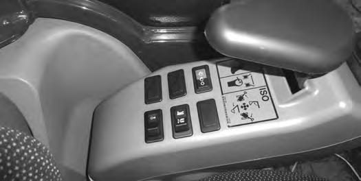
Press the coupler ON / OFF switch (Item 1) [Figure 118] to the left (ON) position to enable the pin grabber quick coupler feature. The switch will illuminate when in the ON position and a buzzer will sound.
Press and release the INTENT switch (Item 2) within five seconds. (The buzzer will continue to sound and the light (Item 1) [Figure 118] will stay ON.)
NOTE:If pin grabber quick coupler, the switch and / or the buzzer do not operate correctly, see troubleshooting chart.
(See Pin Grabber Quick Coupler Troubleshooting on Page 176.)
Roll the coupler out. Move the arm toward the attachment. Reposition the boom, arm and coupler until the coupler (Item 1) [Figure 120] is position over the attachment pin. Raise the attachment up slightly.

Continue to curl the quick coupler until the locking clasp (Item 1) [Figure 119] moves in fully.
Curl the quick coupler in fully [Figure 121]
Press the coupler ON / OFF switch (Item 1) [Figure 118] to the right, (OFF) position. The switch light and buzzer will tur n OFF.

Continue to curl the attachment in for an additional ten seconds to allow the locking clasp to move and lock to the attachment pins.
With the attachment as low to the ground as possible, curl the attachment out and in several times to ensure the attachment is secured to the coupler.

Lower the attachment flat to the ground.

ATTACHMENTS (CONT’D)
Installing And Removing The Attachment (Pin Grabber Quick Coupler) (Cont’d)

Installation (Cont’d)
Figure 122
Visually check that the green locking clasp (Item 1) [Figure 122] is FULLY ENGAGED AND LOCKED
Warning
Keep all bystanders 6 m (20 ft) away from equipment when operating. Contact with moving parts, a trench cave-in or flying objects can cause injury or death.
W-2119-0910
Warning
AVOID INJURY OR DEATH
The quick coupler locking clasps must be fully engaged and locked to the attachment pins. Failure to fully engage the locking clasps can allow attachment to come off.
W-2978-0317
ATTACHMENTS (CONT’D)
Installing And Removing The Attachment (Pin Grabber Quick Coupler) (Cont’d)
Removal
NOTE: Removal and installation of the bucket is shown. The procedure is the same for other attachments. Disconnect any hydraulic lines that are operated by hydraulic power before removing any attachments (breaker, auger, etc.).
Warning
Keep all bystanders 6 m (20 ft) away from equipment when operating. Contact with moving parts, a trench cave-in or flying objects can cause injury or death.
W-2119-0910
Press the coupler ON / OFF switch (Item 1) [Figure 125] to the left (ON) position to enable the pin grabber quick coupler feature. The switch will illuminate when in the ON position and a buzzer will sound.
Press and release the INTENT switch (Item 2) within five seconds. (The buzzer will continue to sound and the light (Item 1) [Figure 125] will stay ON.)
Move the right joystick (Item 1) [Figure 123] to the left (IN) and continue to curl the quick coupler [Figure 124] The coupler locking clasps will lift fully to unlock the attachment from the quick coupler.
Move the right joystick (Item 1) [Figure 123] to the left (IN) and curl the quick coupler (Item 1) [Figure 124] fully.
With the attachment slightly off of the ground, roll the quick coupler back until the coupler starts to disengage from the attachment [Figure 126]
ATTACHMENTS (CONT’D)
Installing And Removing The Attachment (Pin Grabber Quick Coupler) (Cont’d)
Removal (Cont’d)
Figure 127
Roll the quick coupler back fully.
Lower the boom and arm until the attachment is on the ground and the quick coupler is disengaged from the attachment pins.
Move the arm away the excavator until the quick coupler is clear of the attachment [Figure 127]
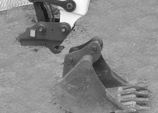
Figure 128
Press the coupler ON / OFF switch (Item 1) [Figure 128] to the right, (OFF) position. The switch light and buzzer will tur n OFF.
ATTACHMENTS (CONT’D)
Installing And Removing The Attachment (Pin-On X-Change)
Installation
NOTE: Installation and removal of the bucket is shown. The procedure is the same for other attachments. Disconnect any hydraulic lines that are operated by hydraulic power before removing any attachments (breaker, auger, etc.).
Warning
AVOID INJURY OR DEATH
Never use attachments or buckets which are not approved by Bobcat Company. Buckets and attachments for safe loads of specified densities are approved for each model. Unapproved attachments can cause injury or death.
W-2052-0907
Warning
Both hydraulic pins must be fully extended through the attachment mounting holes and locked with both retainer pins and clips. Failure to fully engage and lock hydraulic pins can allow attachment to come off and cause serious injury or death.


W-2507-0706
Inspect the pin (Item 1) [Figure 129] for wear or damage. Replace the pin as needed.
Apply a light coat of grease to the ends of the pin (Item 2) [Figure 129]
ATTACHMENTS (CONT’D)
Installing And Removing The Attachment (Pin-On X-Change) (Cont’d)
Installation (Cont’d)
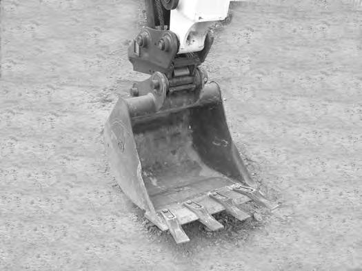
Raise the boom until the pins (Item 1) engage the hooks (Item 2) [Figure 131] on the bucket.
Raise the boom and extend the bucket cylinder until the X-Change contacts the attachment back [Figure 132]
With the arm vertical, lower the boom until the hooks (Item 1) of the bucket disengage the pins (Item 2) of the X-Change and the plate (Item 3) [Figure 132] fully engages in the bucket crossmember.

Warning
Keep all bystanders 6 m (20 ft) away from equipment when operating. Contact with moving parts, a trench cave-in or flying objects can cause injury or death.
W-2119-0910
ATTACHMENTS (CONT’D)
Installing And Removing The Attachment (Pin-On X-Change) (Cont’d)

Installation (Cont’d)
Stop the engine. Turn the start key to the ON position and move both hydraulic control levers to relieve hydraulic pressure.
Drive the pin (Item 1) [Figure 133] through the bucket mount and X-Change.
Install the retainer pin (Item 1) [Figure 134]
Check for proper installation.
Lift the attachment and fully extend and retract the bucket cylinder.
ATTACHMENTS (CONT’D)
Installing And Removing The Attachment (Pin-On X-Change) (Cont’d)

Removal
Use the pin on X-Change when installing new attachments that are equipped with the pin on X-Change bracket.
NOTE: Removal and installation of the bucket is shown. The procedure is the same for other attachments. Disconnect any hydraulic lines that are operated by hydraulic power before removing any attachments (breaker, auger, etc.).
Warning
Avoid Injury Or Death
Never use attachments or buckets which are not approved by Bobcat Company. Buckets and attachments for safe loads of specified densities are approved for each model. Unapproved attachments can cause injury or death.
W-2052-0907
With the engine off, turn the start key to the ON position and move both hydraulic control levers to relieve hydraulic pressure.
ATTACHMENTS (CONT’D)
Installing And Removing The Attachment (Pin-On X-Change) (Cont’d)

Removal (Cont’d)
Warning
AVOID INJURY OR DEATH
Wear safety glasses to prevent eye injury when any of the following conditions exist:
•When fluids are under pressure.
•Flying debris or loose material is present.
•Engine is running.
•Tools are being used.
Start
ATTACHMENTS (CONT’D)
Installing And Removing The Attachment (Pin-On X-Change) (Cont’d)
Removal (Cont’d)
ATTACHMENTS (CONT’D)
Installing And Removing The Attachment (Pin-On Attachment)
Installation
Warning
AVOID INJURY OR DEATH
Stop the machine on a firm flat surface. When removing or installing attachments (such as a bucket), always have a second person in the operator’s seat, give clear signals and work carefully.
Install the arm into the bucket and align the mounting hole.
Install the pin (Item 1) [Figure 140] and washers.
Install the link (Item 2) in the bucket and align the mounting hole. Install the pin (Item 3) [Figure 140] and washers.


Removal
Park the excavator on a flat surface and lower the bucket fully
Remove the two retainer pins (Item 1) [Figure 141].
Remove the washers and pins (Items 1 and 3) [Figure 140]
Do not damage the dust seals in the arm.
Warning
AVOID INJURY OR DEATH
Never use attachments or buckets which are not approved by Bobcat Company. Buckets and attachments for safe loads of specified densities are approved for each model. Unapproved attachments can cause injury or death.
ATTACHMENTS (CONT’D)
Installing And Removing The Pro Clamp System Tool

Installation
Warning
AVOID INJURY OR DEATH
Keep fingers and hands out of pinch points when installing and removing implement or attachment.
W-2571-1212
Warning
Keep all bystanders 6 m (20 ft) away from equipment when operating. Contact with moving parts, a trench cave-in or flying objects can cause injury or death.
W-2119-0910
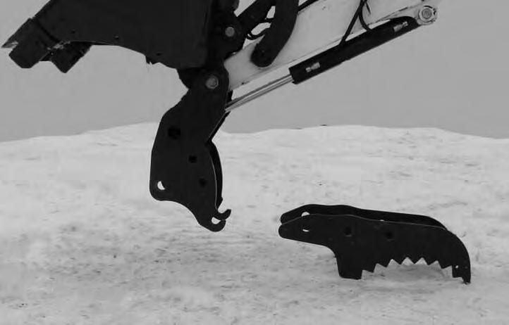
Enter the excavator and start the engine. (See PRESTARTING PROCEDURE on Page 60.)

NOTE: To install the clamp tool (Item 1) onto the clamp base (Item 2), the clamp tool (Item 1) can be positioned in either configuration as shown in [Figure 142].
Move the arm toward the clamp tool.
Engage the clamp base hooks (Item 3) onto the clamp anchors (Item 4) [Figure 142]
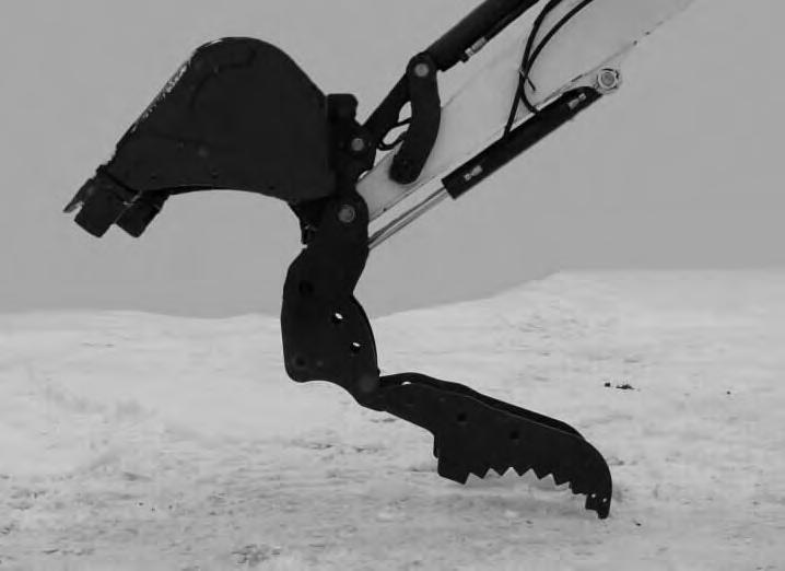
Retract the bucket cylinder (Item 1) [Figure 143] until the clamp tool is supported by the clamp hooks and the tool anchors.

ATTACHMENTS (CONT’D)
Installing And Removing The Pro Clamp System Tool (Cont’d)
Installation (Cont’d)
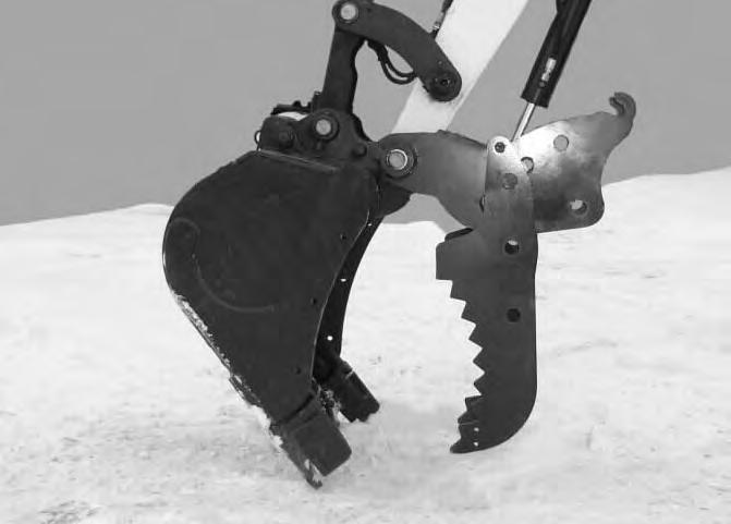
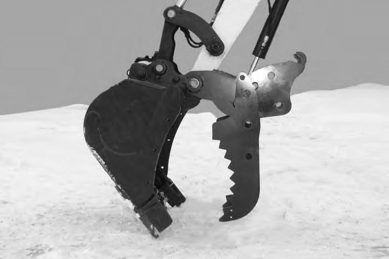
Raise the boom until the clamp tool (Item 1) [Figure 144] is slightly off the ground.
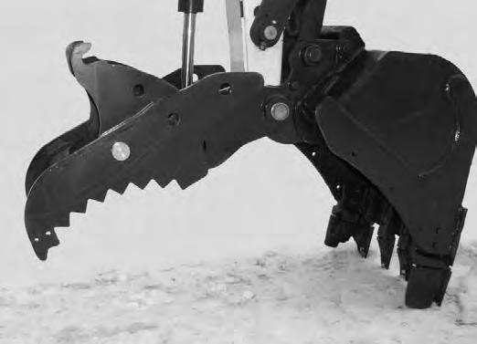
Rotate the bucket (Item 1) [Figure 146] down until it is in the position shown. Lower the boom until the bucket is fully on the ground.
The bottom of the clamp tool (Item 2) [Figure 146] must be slightly off the ground when the bucket is resting on the ground in order to rotate the tool to install the pins.
NOTE:The clamp tool can become unstable and fall off the clamp mount if the clamp tool (Item 2) [Figure 146] is allowed to contact the ground.


NOTE:The clamp tool (Item 2) can be positioned in multiple arrangements depending on which mounting holes are used. See [Figure 147] and [Figure 148] for the approved positions for the clamp tool.
Stop the engine and exit the excavator. (See STOPPING THE ENGINE AND LEAVING THE EXCAVATOR on Page 68.)
Continue to retract the bucket cylinder until the clamp tool (Item 1) [Figure 145] slides into the (index point B) [Figure 144] and [Figure 145].
ATTACHMENTS (CONT’D)
Installing And Removing The Pro Clamp System Tool (Cont’d)
Installation (Cont’d)
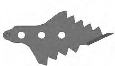
Material Tool Arrangements
Figure 147
* Material Tool Weight: 27 kg

ATTACHMENTS (CONT’D)
Installing And Removing The Pro Clamp System Tool (Cont’d)
Installation (Cont’d)
Grading And Clam Tool Arrangements
Figure 148
* Grading And Clam Tool Weight: 30 kg (65 lb)

** Note: See the correct operating procedure when using the grading tool for grading. (See Using The Pro Clamp System (If Equipped) on Page 98.)

ATTACHMENTS (CONT’D)
Installing And Removing The Pro Clamp System Tool (Cont’d)
Installation (Cont’d)
Figure 149
Warning
AVOID INJURY OR DEATH
Keep fingers and hands out of pinch points when installing and removing implement or attachment.
W-2571-1212
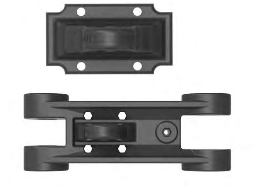
For aligning the clamp tool and base assembly, there are three mounting holes (Item 1, 2 and 3). For indexing the clamp tool, there are two indexing points on the base assembly (Item A and B) [Figure 149]
Use [Figure 147] and [Figure 148] to determine which index point is used for the desired tool position.
Figure 150
Install a pin (Item 1) [Figure 151] in the mounting hole on each side. Install the lock pins (Item 1) [Figure 154].
NOTE:When installing the clamp tool, always install the pins in the hole 1 [Figure 149] first. Hole 1 [Figure 149] will always be used for mounting the tools.
Move the clamp tool along the base assembly to the desired indexing point (A or B) [Figure 150]
NOTE: The clamp tool anchors must be located in one of the indexing points on the base assembly for the mounting holes to align. The base assembly hooks are for lifting the clamp tool only. The hooks cannot be used as an indexing point for mounting hole alignment.

Lifting the bottom of the clamp tool, use the anchors and indexing point as a hinge to align the mounting holes (Item 1) [Figure 150]
NOTE:When repositioning or removing the Pro Clamp System tool, remove the pins from positions 2 or 3 first. The pin in location 1 should always be the last pin removed or the first pin installed [Figure 149].
ATTACHMENTS (CONT’D)
Installing And Removing The Pro Clamp System Tool (Cont’d)
Installation (Cont’d)
Rotate the clamp tool to the desired angle, aligning the other mounting holes [Figure 152]


Note:Always install ALL of the mounting pins and the retaining pins.
Important
Always install all of the mounting pins and retainer pins. Failure to do so will cause structural damage.
ATTACHMENTS (CONT’D)
Installing And Removing The Pro Clamp System Tool (Cont’d)
Removal
Park the excavator on a flat and level surface. Position the bucket as shown in [Figure 155] and lower the boom until the bucket is fully on the ground.
Stop the engine and exit the excavator.
Remove the retainer pins (Item 1) [Figure 154]
NOTE:When repositioning or removing the Pro Clamp System tool, remove the pins from positions 2 or 3 first. The pin in location 1 should always be the last pin removed or the first pin installed [Figure 149].
Hold the bottom of the clamp tool (Item 1) and remove the pin (Item 2) [Figure 155] from each side.
Lift on the bottom of the clamp tool using the anchors as a fulcrum to take pressure off of the pins (Item 2) and remove pins (Item 2) [Figure 156] (both sides). Rotate the tool down until it hangs freely straight down.
Rotate the clamp tool until the anchors (Item 1) [Figure 156] are contacting the indexing point.
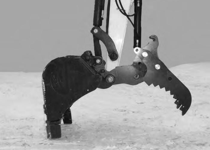
Slightly raise the boom and retract the bucket cylinder fully. Lower the boom until the tip of the clamp tool is touching the ground. Extend the clamp cylinder and slightly lower the boom and rotate the clamp tool forward until the clamp tool is fully on the ground [Figure 157].
Lower the boom and move the arm forward until the hooks of the clamp mount (Item 1) are disengaged from the clamp tool anchors (Item 2) [Figure 158]

OPERATING PROCEDURE Inspect The Work Area
Before beginning operation, inspect the work area for unsafe conditions.
Look for sharp drop-offs or rough terrain. Have underground utility lines (gas, electrical, water, sewer, irrigation, etc.) located and marked. Work slowly in areas of underground utilities.
Remove objects or other construction material that could damage the excavator or cause personal injury.
Always check ground conditions before starting your work:
•Look for signs of instability such as cracks or settlement.
•Be aware of weather conditions that can affect ground stability.
•Check for adequate traction if working on a slope.
Basic Operating Instructions
When operating on a public road or highway, always follow local regulations. For example: A slow moving vehicle (SMV) sign, or direction signals may be required.
Run the engine at low idle speed to warm the engine and hydraulic system before operating the excavator.
Important
Machines warmed up with moderate engine speed and light load have longer life.
I-2015-0284
New operators must operate the excavator in an open area without bystanders. Operate the controls until the excavator can be handled at an efficient and safe rate for all conditions of the work area.
Operating Near An Edge Or Water
Keep the excavator as far back from the edge as possible and the excavator tracks perpendicular to the edge so that if part of the edge collapses, the excavator can be moved back.
Always move the excavator back at any indication the edge may be unstable.
Lowering The Work Equipment (Engine STOPPED)
The hydraulic control levers control the movement of the boom, arm, bucket and upperstructure slew functions.
The console must be in the locked down position, and the key switch in the ON position.
Use the control lever to lower the boom.
The joystick lock switch disengages the hydraulic control functions from the joysticks when the console are raised [Figure 159].
NOTE: If the engine stops, the boom / bucket (attachments) can be lowered to the ground using hydraulic pressure in the accumulator.
The control console must be in the locked down position, and the key switch in the ON position.
Use the control lever to lower the boom.
Lower the control console to engage the hydraulic control functions of the joysticks [Figure 159].

OPERATING PROCEDURE (CONT’D)
Object Handling
Do not exceed the Rated Lift Capacity. (See Lift Chart (7188426) With Standard Arm on Page 205.) or (See Lift Chart (7188428) With Long Arm on Page 211.) or (See Lift Chart (7221250) With Extendable Arm on Page 214.)
Warning
AVOID INJURY OR DEATH
Do not exceed rated lift capacity. Excessive load can cause tipping or loss of control.
W-2374-0500
Extend the bucket cylinder completely and lower the boom to the ground. Stop the engine.
Wrap the chain assembly around the bucket mounting plate.
Make sure the load is evenly weighted and centered on the lifting chain, and is secured to prevent the load from shifting [Figure 160].
Lift and position the load. Once the load is in position and tension is removed from the lift chain (secondary lift system), remove the secondary lift system.
NOTE:When transporting the excavator, when using hydraulically operated attachments, or when lifting objects, the extendable arm must be locked in the retracted position. Fully retract the arm and install the pin and the retainer pin in the locked position. (See Extending The Arm on Page 104.)

OPERATING PROCEDURE (CONT’D)
Object Handling With The Lifting Device
The excavator must be equipped with the optional lift eye link (Item 1) [Figure 162], the boom and arm load hold valves and the overload warning device option. See your Bobcat dealer for available Kits.
Warning
AVOID INJURY OR DEATH
•Do not exceed rated lift capacity.
•Excessive load can cause tipping or loss of control.
•Excessive load can cause failure of the lift eye and cause the load to drop.
W-2991-0714
Do not exceed the machine’s Rated Lift Capacity or the Rated Lift Load (RLL) of the lifting device (lift eye). (See Lift Chart (7188426) With Standard Arm on Page 205.), (See Lift Chart (7188440) With Standard Arm W/ Counterweight on Page 208.), (See Lift Chart (7188428) With Long Arm on Page 211.) or (See Lift Chart (7221250) With Extendable Arm on Page 214.)
Make sure the secondary lifting system (chain) is of sufficient strength to lift the object.

NOTE: Visually check the lifting eye, the clevis and the secondary lifting system (chain) for any damage. Replace any damage components before lifting. See your Bobcat dealer for replacement lift eye and clevis.
The maximum RLL (Item 1) [Figure 161] is shown on the lifting device.
Extend the bucket cylinder completely and lower the boom to the ground. Stop the engine. Exit the excavator. (See STOPPING THE ENGINE AND LEAVING THE EXCAVATOR on Page 68.)
OPERATING PROCEDURE (CONT’D)
Object Handling With The Lifting Device

Install a lift chain (Item 1) (or other type of lifting device) through the clevis (Item 2) [Figure 163] and connect to the object to be lifted.

NOTE:Always use chains or other types of lifting devices that are intended for this type of use and that are of adequate strength for the object being lifted.
Enter the excavator, fasten the seat belt and start the engine. (See PRE-STARTING PROCEDURE on Page 60.)
Make sure the load is evenly weighted and centered on the lifting chain (or other type of lifting device), and is secured to prevent the load from shifting [Figure 165]
Operate the controls slowly and smoothly to avoid suddenly swinging the lifted load.
Lift and position the load. When the load is placed in a secured position and tension is removed from the lift chain, remove the chain from the load and from the lift eye.
Press the switch (Item 1) [Figure 164] to the left to activate the overload warning device.
OPERATING PROCEDURE (CONT’D)
Lift Capacity
The lifting capacities were calculated with a machine that was equipped with a standard bucket and the pin-on Xchange. The difference between the weight of the attachment and the standard bucket, the pin-on Xchange and the quick coupler (if equipped), and the hydraulic clamp (if equipped) must be subtracted.
WARNING
AVOID INJURY OR DEATH
Do not exceed rated lift capacity. Excessive load can cause tipping or loss of control.
W-2374-0500
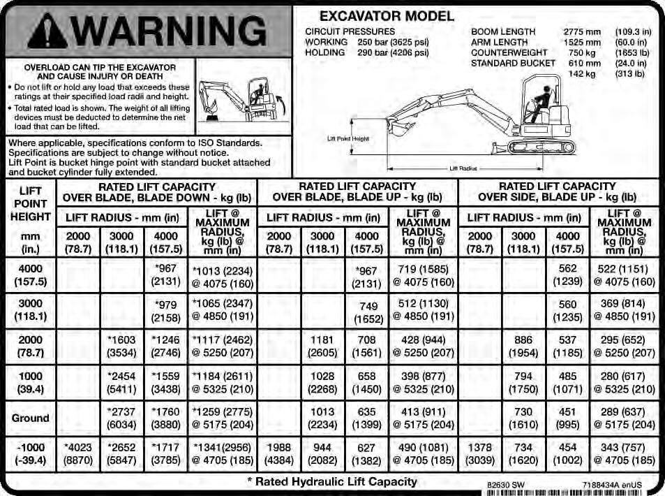
EXAMPLE OF LIFT CAPACITY CHART
* 1246 kg (2746 lb)
7188434
The following example will show how to calculate the lift capacity differences between the lift capacity charts with standard equipment and when using optional equipment.
The standard equipment weights used when determining lift capacity are as follows:
Standard Bucket = 142 kg (313 lb)
Pin-On X-Change = 28 kg (62 lb)
The following lists the weight of the optional quick couplers and hydraulic clamp:
•Pin-on X-Change = 28 kg (62 lb)
•Hydraulic X-Change = 40 kg (87 lb)
•Pin Grabber Quick Coupler = 65 kg (143 lb)
•Lehnhoff® Quick Coupler = 30 kg (66 lb)
•Klac™ Quick Coupler = 43 kg (95 lb)
•TAG Quick Coupler = 26 kg (58 lb)
•Hydraulic Clamp And Cylinder = 86 kg (190 lb)
•Hydraulic Pro-Clamp, Clamp Tool And Cylinder = 144 kg (317 lb)
•Optional Buckets and Attachments (See NOTE below)
NOTE:For bucket weights, see your Bobcat dealer. For attachment weights, see the attachment Operation & Maintenance Manual.
OPERATING PROCEDURE (CONT’D)
Lift Capacity (Cont’d)
The following is an example for determining the lift capacity using the sample chart shown above [Figure 166]
- Machine Position: Over Blade, Blade Down
- Lift Radius: 4000 mm (125.5 in)
- Lift Point Height: 2000 mm (78.7 in)
- Hydraulic X-Change
- Hydraulic Clamp and Cylinder
- Standard Bucket
1. Obtain Lift Capacity from Chart: 1246 kg (2746 lb)
2. Subtract the difference between the weight of the standard configuration (Pin-On X-change and Standard Bucket) and optional equipment which in this case is the Hydraulic X-Change and the Hydraulic Clamp.
Quick Coupler (Pin-On X-Change minus Hydraulic X-change): 28 kg (62 lb) - 40 kg (87 lb) = minus 12 kg (25 lb)
Hydraulic Clamp and Cylinder: 86 kg (190 lb)
3. Calculate actual Lift Capacity for machine as configured:
1246 kg (2746 lb) - 12 kg (25 lb) (coupler difference) - 86 kg (190 lb) (hydraulic clamp and cylinder) = 1148 kg (2531 lb)
* The lift capacity charts (decals) are based off of ISO 10567: 2007. The lifting capacities are defined as the lower value of 75% of tipping load or 87% of the hydraulic lift capacity.