12 minute read
Safety Alert Symbol


This symbol with a warning statement means: “Warning, be alert! Your safety is involved!” Carefully read the message that follows.
Warning
Operator must have instructions before operating the machine. Untrained operators can cause injury or death.
W-2001-0502
Important
This notice identifies procedures which must be followed to avoid damage to the machine.
I-2019-0284
Danger
The signal word DANGER on the machine and in the manuals indicates a hazardous situation which, if not avoided, will result in death or serious injury.
D-1002-1107
Warning
The signal word WARNING on the machine and in the manuals indicates a potentially hazardous situation which, if not avoided, could result in death or serious injury.
W-2044-1107
The Bobcat excavator and attachment must be in good operating condition before use.
Check all of the items on the Bobcat Service Schedule Decal under the 8-10 hour column or as shown in the Operation & Maintenance Manual.
Safe Operation Needs A Qualified Operator
For an operator to be qualified, he or she must not use drugs or alcoholic drinks which impair alertness or coordination while working. An operator who is taking prescription drugs must get medical advice to determine if he or she can safely operate a machine.
A Qualified Operator Must Do The Following:
Understand the Written Instructions, Rules and Regulations
•The written instructions from Bobcat Company include the Delivery Report, Operation & Maintenance Manual, Operator’s Handbook, Safety Manual and machine signs (decals).
•Check the rules and regulations at your location. The rules may include an employer’s work safety requirements. Regulations may apply to local driving requirements or use of a Slow Moving Vehicle (SMV) emblem. Regulations may identify a hazard such as a utility line.
Have Training with Actual Operation
•Operator training must consist of a demonstration and verbal instruction. This training is given by your Bobcat dealer before the product is delivered.
•The new operator must start in an area without bystanders and use all the controls until he or she can operate the machine and attachment safely under all conditions of the work area. Always fasten seat belt before operating.
•Operator Training Courses are available from your Bobcat dealer in English and Spanish. They provide information for safe and efficient equipment operation. Safety videos are also available.
•Service Safety Training Courses are available from your Bobcat dealer. They provide information for safe and correct service procedures.
Know the Work Conditions
•Know the weight of the materials being handled. Avoid exceeding the Rated Lift Capacity of the machine. Material that is very dense will be heavier than the same volume of less dense material. Reduce the size of load if handling dense material.
•The operator must know any prohibited uses or work areas, for example, he or she needs to know about excessive slopes.
•Know the location of any underground lines. Call local utilities or the TOLL FREE phone number found in the Before Operation section of this manual.
•Wear tight fitting clothing. Always wear safety glasses when doing maintenance or service. Safety glasses, respiratory equipment, hearing protection or Special Applications Kits are required for some work. See your Bobcat dealer about Bobcat safety equipment for your model.
SAFETY INSTRUCTIONS (CONT’D)
Avoid Silica Dust
Cutting or drilling concrete containing sand or rock containing quar tz may result in exposure to silica dust. Do not exceed Permissible Exposure Limits (PEL) to silica dust as determined by OSHA or other job site Rules and Regulations. Use a respirator, water spray or other means to control dust. Silica dust can cause lung disease and is known to the state of California to cause cancer.
Fire Prevention
Maintenance
The machine and some attachments have components that are at high temperatures under normal operating conditions. The primary source of high temperatures is the engine and exhaust system. The electrical system, if damaged or incorrectly maintained, can be a source of arcs or sparks.
Flammable debris (leaves, straw, etc.) must be removed regularly. If flammable debris is allowed to accumulate, it can cause a fire hazard. Clean often to avoid this accumulation. Flammable debris in the engine compartment is a potential fire hazard.
The operator’s area, engine compartment and engine cooling system must be inspected every day and cleaned if necessary to prevent fire hazards and overheating.
All fuels, most lubricants and some coolant mixtures are flammable. Flammable fluids that are leaking or spilled onto hot surfaces or onto electrical components can cause a fire.
Operation
Do not use the machine where exhaust, arcs, sparks or hot components can contact flammable material, explosive dust or gases.
Electrical
Check all electrical wiring and connections for damage. Keep the battery terminals clean and tight. Repair or replace any damaged part or wires that are loose or frayed.
Battery gas can explode and cause serious injury. Use the procedure in the Operation & Maintenance Manual for connecting the battery and for jump starting. Do not jump start or charge a frozen or damaged battery. Keep any open flames or sparks away from batteries. Do not smoke in battery charging area.
FIRE PREVENTION (CONT’D)
Hydraulic System
Check hydraulic tubes, hoses and fittings for damage and leakage. Never use open flame or bare skin to check for leaks. Hydraulic tubes and hoses must be properly routed and have adequate support and secure clamps. Tighten or replace any parts that show leakage.
Always clean fluid spills. Do not use gasoline or diesel fuel for cleaning parts. Use commercial nonflammable solvents.
Fueling
Stop the engine and let it cool before adding fuel. No smoking! Do not refuel a machine near open flames or sparks. Fill the fuel tank outdoors.
Ultra Low Sulfur Diesel (ULSD) poses a greater static ignition hazard than earlier diesel formulations with higher Sulfur content. Avoid death or serious injury from fire or explosion. Consult with your fuel or fuel system supplier to ensure the delivery system is in compliance with fueling standards for proper grounding and bonding practices.
Starting
Do not use ether or starting fluids on any engine that has glow plugs or air intake heater. These starting aids can cause explosion and injure you or bystanders.
Use the procedure in the Operation & Maintenance Manual for connecting the battery and for jump starting.
Spark Arrester Exhaust System
The spark arrester exhaust system is designed to control the emission of hot particles from the engine and exhaust system, but the muffler and the exhaust gases are still hot.
Check the spark arrester exhaust system regularly to make sure it is maintained and working properly. Use the procedure in the Operation & Maintenance Manual for cleaning the spark arrester muffler (if equipped).
Welding And Grinding
Always clean the machine and attachment, disconnect the battery, and disconnect the wiring from the Bobcat controllers before welding. Cover rubber hoses, battery and all other flammable parts. Keep a fire extinguisher near the machine when welding.
Have good ventilation when grinding or welding painted parts. Wear dust mask when grinding painted parts. Toxic dust or gas can be produced.
Dust generated from repairing nonmetallic par ts such as hoods, fenders or covers can be flammable or explosive. Repair such components in a well ventilated area away from open flames or sparks.
Fire Extinguishers
Know where fire extinguishers and first aid kits are located and how to use them. Inspect the fire extinguisher and service the fire extinguisher regularly. Obey the recommendations on the instructions plate.
Publications And Training Resources
The following publications are also available for your Bobcat excavator. You can order them from your Bobcat dealer.
For the latest information on Bobcat products and the Bobcat Company, visit our Web site at Bobcat.com/ training or Bobcat.com.
OPERATION & MAINTENANCE MANUAL
6990444enUS
Complete instructions on the correct operation and the routine maintenance of your Bobcat excavator.
SAFETY MANUAL
6901951 (English and Spanish)
Gives basic safety procedures and warnings for your Bobcat excavator.
COMPACT EXCAVATOR OPERATOR TRAINING COURSE
7249283 (English) 7249286 (Spanish)
Introduces operator to step-by-step basics of skid-steer excavator operation.
SERVICE MANUAL
6989433enUS
Complete maintenance instructions for your Bobcat excavator.
OPERATOR’S HANDBOOK
6990434enUS
Gives basic operation instructions and safety warnings.
OPERATOR SAFETY DVD
6904762 (English and Spanish)
DVD gives basic safety instructions for many Bobcat products including excavators.
EXCAVATOR SERVICE SAFETY TRAINING COURSE
6900916
Introduces service technicians to step-by-step basics of proper and safe skid-steer excavator maintenance and servicing procedures.
EXCAVATOR SAFETY VIDEO (Mobile device with quick response code application required)
Scan the code above to watch the excavator safety video or view at Bobcat.com/training
MACHINE SIGNS (DECALS)
Follow the instructions on all the Machine Signs (Decals) that are on the excavator. Replace any damaged machine signs and be sure they are in the correct locations. Machine signs are available from your Bobcat excavator dealer.
MACHINE SIGNS (DECALS) (CONT’D)
Follow the instructions on all the Machine Signs (Decals) that are on the excavator. Replace any damaged machine signs and be sure they are in the correct locations. Machine signs are available from your Bobcat excavator dealer.

MACHINE SIGNS (DECALS) (CONT’D)
Pictorial Only Safety Signs
Safety signs are used to alert the equipment operator or maintenance person to hazards that may be encountered in the use and maintenance of the equipment. The location and description of the safety signs are detailed in this section. Please become familiarized with all safety signs installed on the excavator.
Vertical Configuration
NOTE: See the numbered MACHINE SIGNS (DECALS) on Page 14 and MACHINE SIGNS (DECALS) (Cont’d) on Page 15 for the machine location of each corresponding numbered pictorial only decals as shown below.
1.Thrown Or Flying Objects (7168039)
This safety sign is located on the outside of both tracks.
Warning
Horizontal Configuration
High pressure grease can cause serious injury. Do not loosen grease fitting. Do not loosen bleed fitting more than 1 - 1/2 turns.
Read and understand the Operation & Maintenance Manual for more information.
W-2516-0110
2. Thrown or Flying Objects (7169291)
This safety sign is located on the gas spring in the engine compartment.
The format consists of the hazard panel(s) and the avoidance panel(s):
Hazard panels depict a potential hazard enclosed in a safety alert triangle.


Avoidance panels depict actions required to avoid the hazards.
A safety sign may contain more than one hazard panel and more than one avoidance panel.
Warning
High pressure gas can cause serious injury or death. Do not open. Opening cylinder can release rod.
W-2523-0106

Intended Use
This machine is classified as an Excavator as defined in ISO 6165. This machine has tracks and commonly a mounted bucket for the principle intended functions of excavating, loading and backfilling loose materials such as earth, gravel, or crushed rock.
Additional Bobcat approved attachments allow this machine to perform other tasks described in the attachment Operation & Maintenance Manuals.
Examples of intended use include:
AVOID INJURY OR DEATH
Do not exceed rated lift capacity. Excessive load can cause tipping or loss of control.

W-2374-0500
Warning
AVOID INJURY OR DEATH
Check area to be excavated for overhead or underground electrical power lines. Keep a safe distance from electrical power lines.
50
Keep all bystanders 6 m (20 ft) away from equipment when operating. Contact with moving parts, a trench cave-in or flying objects can cause injury or death. W-2119-0910

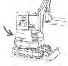
Avoid impacting objects with the blade. Damage to blade and undercarriage components may occur. I-2256-0507
Instruments And Consoles
DESCRIPTION FUNCTION / OPERATION
1 Left Joystick (See HYDRAULIC CONTROLS on Page 44.)

2 Hor n Press the switch on the bottom of the left joystick to sound horn.
3 Boom Swing Switch / Secondary
Auxiliary Hydraulic (If Equipped)
4 Wiper / Washer Switch
(If Equipped)
Move the switch to the left to swing the boom to the left. Move the switch to the right to swing the boom to the right. (See Secondary Auxiliary Hydraulics and Boom Swing in this manual.)
Press the switch to the left to turn wiper ON. Press and hold switch to the left to activate window washer. Press the switch to the right to turn wiper OFF.
5 Hydraulic XChange Switch
(If Equipped)
Pin Grabber Quick Coupler ON/OFF Switch
(If Equipped)
6 Beacon / Strobe Light (If Equipped)
7 Pin Grabber Quick Coupler INTENT Switch
(If Equipped)
8 OVERLOAD WARNING SWITCH (If Equipped)
9 Boom Swing Switch / Secondary Auxiliary Hydraulic (If Equipped)
Press and hold the switch to the right to fully retract hydraulic pins. Press and hold the switch to the left to fully extend hydraulic pins.
Press switch to the left to turn the pin grabber quick coupler ON. Press the switch to the right to turn OFF.
Press switch to the left to turn ON the beacon / Strobe light. Press the switch to the right to turn OFF.


Press switch to the left to initiate the quick coupler install or remove mode. (See Installing And Removing The Attachment (Pin Grabber Quick Coupler) in this manual.)
Press switch to the right to enable Overload Warning feature. Press to the left to disable. (See Overload Warning in this manual.)
Move the switch to the right to activate the secondary auxiliary hydraulics. Move the switch to the left for boom swing function. (See Secondary Auxiliary Hydraulics and Boom Swing in this manual.)
INSTRUMENTS AND CONSOLES (CONT’D)
Right Console
Figure 9
REF DESCRIPTION
FUNCTION / OPERATION
1 Right Joystick(See HYDRAULIC CONTROLS in this manual.)

2 Auxiliary Hydraulic SwitchControls the fluid flow to the auxiliary quick couplers (attachment). (See Auxiliary Hydraulics in this manual.)
3 Blade Control Lever Controls raising and lowering the blade. Pushed all the way forward puts blade in float position. (See BLADE LEVER CONTROL in this manual).
4 Engine Speed Control DialControls rpm of the engine. (See ENGINE SPEED CONTROL DIAL in this manual).
5 Two-Speed Button (Without Angle Blade Option) Engages and disengages High Range Travel Speed. (See Two-Speed Travel in this manual).
5A Two-Speed Button (With Angle Blade Option) Engages and disengages High Range Travel Speed. (See Two-Speed Travel in this manual). (Also see Angle Blade in this manual.) 6 Motion Alarm Cancel SwitchThis switch temporarily disables the motion alarm. (See MOTION ALARM SYSTEM on Page 41.)
7 Not Used
8 Auxiliary Power Outlet12 volt receptacle for accessories. 9 Key Switch
Always perform the PRE-STARTING PROCEDURE. (See PRE-STARTING PROCEDURE in this manual), before starting the engine. (See STARTING THE ENGINE in this manual). 10 Air Conditioning Switch (If Equipped)
Press top of switch to turn air conditioner ON (light in switch will be ON), Press bottom of switch to turn OFF.
11 Fan Motor Switch (If Equipped)Turn clockwise to increase fan speed; counterclockwise to decrease.
12 Temperature Control (If Equipped) Turn clockwise to increase temperature; counterclockwise to decrease.
13 Instrument Panel See Standard or Deluxe Instrument Panel 14 Keyless (If Equipped) (Always perform the PRE-STARTING PROCEDURE, (See PRE-STARTING PROCEDURE in this manual), before starting the engine. (See STARTING THE ENGINE in this manual).
NOTE:Always turn key switch and all accessories to OFF position when the engine is stopped, the battery will discharge if the key is left ON.
INSTRUMENTS AND CONSOLES (CONT’D)
Instrument Panel - Standard

1 LIGHTSPress once for work lights. (Left green LED illuminates.) Press again to turn all lights off. (Left green LED off.)
Press and hold 5 seconds to display software version in display screen.
2 Auto Idle FeaturePress once to turn Auto Idle Feature ON. (Left green LED illuminates.) Press a second time to turn OFF. (Left and right green LEDs off.) (See Auto Idle Feature in this manual).
3 Auxiliary Hydraulic ButtonPress once to enable auxiliary hydraulic function. (Left green LED illuminates.) Continue to press and release to scroll through the selectable auxiliary hydraulic setting (3-2-1-OFF).
Press and hold (minimum of one second) to enable the continuous flow auxiliary hydraulic feature. (Right green LED illuminates.) Continue to press and release to scroll through the continuous flow selectable auxiliary hydraulic settings (3-2-1-OFF).
(See Auxiliary Hydraulics in this manual)
4 Information Cycles through (after each button press) (The following information is displayed in the Data Display Screen, Item 6):
•Hourmeter (On startup)
•Job Clock (1 and 2)
•Engine rpm
•Battery voltage
•Maintenance clock (Press and hold 7 seconds when displayed to reset the maintenance clock.)
•Service codes*
5 Engine Temperature Gauge Shows the engine coolant temperature.
INSTRUMENTS AND CONSOLES (CONT’D)
Instrument Panel - Standard (Cont’d)
REF. NO. DESCRIPTION
FUNCTION / OPERATION
6 Data Display ScreenThe data display screen shows the Hourmeter at start up and then changes to engine rpm during normal operation of the excavator. When preheat is activated, the display screen will show the remaining preheat time. Can also be used to display Job Clock, Engine rpm, and Selectable Auxiliary Hydraulic Flow. (See Job Clock in this manual).
7 Fuel GaugeShows the amount of fuel in the tank.
8 Seat BeltFasten Seat Belt Reminder - Light stays on for 45 seconds to remind operator to fasten seat belt.
9
Not used for this model.
10 Not used for this model.
11 Left Console LockoutIcon ON when left console is raised. Icon OFF when left console is lowered.
12 General Warning **Malfunction with one or more machine functions. (See Service Codes in this manual.)
13 High Range Engaged ***Icon is illuminated when two-speed travel is enabled.
14 Engine Coolant Temperature **Engine coolant temperature high or sensor error.
15 Engine Malfunction ** Engine malfunction or failure.
16 Hydraulic System Malfunction **Hydraulic system malfunction or failure.
17 Fuel Fuel level low or sensor error. (Icon is ON when fuel level is low, Icon flashes when fuel sensor fault is activated.)
* See SYSTEM SETUP AND ANALYSIS for Service Code Description. (See DIAGNOSTIC SERVICE CODES on Page 185.)
** Icons will be ON or flashing when diagnostic system indicates a problem. (See DIAGNOSTIC SERVICE CODES on Page 185.)
*** Icons will be flashing when diagnostic system indicates a problem. (See DIAGNOSTIC SERVICE CODES on Page 185.)
INSTRUMENTS AND CONSOLES (CONT’D)
Instrument Panel - Standard (Cont’d)

Indicator Icons
The display screen can display the following information:
•Operating hours
• Job Clock (1 and 2)
•Engine rpm
•Battery voltage
•Maintenance clock countdown
•Service codes
11
The display screen is shown in [Figure 11]. The data display will show operating hours upon startup.
/