7 minute read
SYSTEM SETUP & ANALYSIS


POWER BOB–TACH (OPTION) Inspection And Maintenance
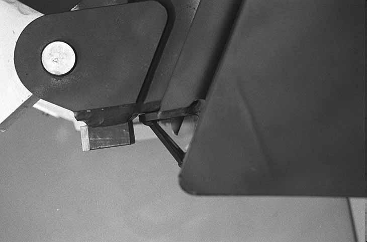
Push and hold the Bob–Tach “WEDGES UP” switch [A] until wedges are fully raised. Push and hold the Bob–Tach “WEDGES DOWN” switch [A] until the wedges are fully down. the wedges must move freely.
The wedges must extend through the holes in the attachment mounting frame (Item 1) [B] and must contact the lower edge of the hole in the attachment [B] and (Item 1) [C].
If the wedge does not contact the lower edge of the hole [C], the attachment will be loose and can come off the Bob–Tach.
Inspect the mounting frame on the attachment and the Bob–Tach, linkages and wedges for excessive wear or damage [D]. Replace any parts including decals and lever that are damaged, bent, or missing. Keep all fasteners tight. Inspect the hoses, tubelines and fittings for leaks. Look for cracked welds. Contact Your Bobcat dealer for repair or replacement parts. Lubricate the wedges. (See SERVICE SCHEDULE, Page 39 and LUBRICATING THE BOBCAT LOADER, Page 70)
B
C
1
D
1
B–15891
N–17047
Wedge Must Contact Lower Edge Of Hole In The Attachment
N–17043

BOBCAT INTERLOCK CONTROL SYSTEM (BICS™)
Deluxe Panel Upgrade
. . . . . . . . . . . . . . . . . . . . . . . . . . . . . . . . . . . . . . . . . . . Icon Identification . . . . . . . . . . . . . . . . . . . . . . . . . . . . . . . . . . . . . . . . . . . . . . . Deluxe Panel Setup . . . . . . . . . . . . . . . . . . . . . . . . . . . . . . . . . . . . . . . . . . . . . Passwords . . . . . . . . . . . . . . . . . . . . . . . . . . . . . . . . . . . . . . . . . . . . . . . . . . . . . Changing the Passwords . . . . . . . . . . . . . . . . . . . . . . . . . . . . . . . . . . . . . . . . . 82 82 82 82 83 83
SYSTEM SETUP & ANALYSIS
BOBCAT INTERLOCK CONTROL SYSTEM (BICS™)
Troubleshooting Chart
19. The following chart shows the effects which can happen to the loader, and the probable causes when the BICS Instrument Panel lights are off. See [A] for location of BICS lights and Icons. Have service procedures performed ONLY BY QUALIFIED BOBCAT SERVICE PERSONNEL.
Press and hold LIGHTS Button (Item 5) [A] for two seconds to view SERVICE CODES in the HOURMETER / CODE DISPLAY (Item 6) [A]. If more than one SERVICE CODE is present, the codes will scroll on the HOURMETER / CODE DISPLAY.
6
5
PRESS FOR CODES
2
1 4
3
B–15551
Indicator
Light Light ON Light OFF
1
PRESS TO OPERATE LOADER Button is pressed. PRESS TO OPERATE LOADER Button is not pressed.
Effect on Operation of Loader When Light is OFF
Lift, tilt and traction functions will not operate.
2
Seat Bar is down. Seat Bar is up. Lift, tilt and traction functions will not operate.
3
Control valve can be used. Control valve cannot be used. Lift, tilt and traction functions will not operate.
4
Loader can be moved forward & backward. Loader cannot be moved forward and backward. Loader cannot be moved forward and backward.
32 SEAT BAR LIFT & TILT VALVE TRACTION
4 NOTES:
Multiple SERVICE CODES and/or Abnormal Symptoms can be caused by corroded or loose ground. Check grounds and both battery connections.
ERROR OFF = shorted to ground or bad fuse, faulty wiring, faulty open relay, no voltage from relay to controller. ERROR ON = shorted to battery voltage, faulty wiring, faulty closed relay.
* Normal BICS operating voltage is less than the electrical system voltage.
SERVICE CODE Means System Error (See Your Bobcat Dealer for Service)
No. of Flashes Service Code Causes
2 11–05 Seat Bar sensor circuit shorted to battery voltage.*
3 11–06 Seat Bar sensor circuit shorted to ground.
1 17–07
2 17–05
3 17–06
3 17–06
1 16–07
2 16–05
3 16–06
5 15–02 Valve output circuit is open. Valve output circuit shorted to battery voltage.* Valve output circuit shorted to ground. Controller not grounded or intermittent ground. Traction lock hold solenoid circuit is open. Traction lock hold solenoid circuit shorted to battery voltage.* Traction lock hold solenoid circuit shorted to ground. Traction lock pull solenoid circuit is shorted to battery voltage.* – ERROR ON (Should be OFF)
6 15–03
Traction lock pull solenoid circuit ERROR OFF (Should be ON). Continuous03–09 System voltage low Flashing 03–10 System voltage high
DELUXE INSTRUMENTATION SERVICE CODES
The hourmeter display on the Left Instrument Panel can change from engine hours to SERVICE CODES (See at right.). These CODES help your dealership analyze monitored functions of your Bobcat loader. Some service procedures must be performed ONLY BY QUALIFIED BOBCAT SERVICE PERSONNEL. Press and hold LIGHTS Button (Item 5) [A] (Page 77) for two seconds to view SERVICE CODES in the display (Item 6) [A] (Page 77). If more than one SERVICE CODE is present, the codes will scroll on the HOURMETER / CODE DISPLAY.
Number Codes List
CODE DESCRIPTION
The following word errors may also be displayed:
REPLY One or both instrument panel(s) not communicating with the controller.
INPUT The controller not communicating with the left instrument panel.
CODE The controller is asking for a password. (Deluxe Panel Only)
ERROR The wrong password was entered. (Deluxe Panel Only)
CODE DESCRIPTION
01–16 Air filter not connected 09–09 Fuel level low
01–17 Air filter plugged
02–16 Hydraulic charge filter not connected 02–17 Hydraulic charge filter plugged
03–09 Battery voltage low 03–10 Battery voltage high 03–11 Battery voltage extremely high 09–21 Fuel level out of range high 09–22 Fuel level out of range low
11–05 Seat bar sensor short to battery 11–06 Seat bar sensor short to ground
12–21 Front auxiliary PWM switch out of range high 12–22 Front auxiliary PWM switch out of range low
03–14 Battery voltage extremely low 12–23 Front auxiliary PWM switch not calibrated
03–22 Battery voltage out of range low
13–05 Fuel shut–off solenoid secondary short to battery 04–09 Engine oil pressure low 13–06 Fuel shut–off solenoid secondary short to ground 04–14 Engine oil pressure extremely low 13–07 Fuel shut–off solenoid secondary open circuit 04–15 Engine oil pressure shutdown level 04–21 Engine oil pressure out of range high 14–02 Fuel shut–off solenoid primary error ON 04–22 Engine oil pressure out of range low 14–03 Fuel shut–off solenoid primary error OFF
05–09 Hydraulic charge pressure low 15–02 Traction lock solenoid primary error ON 05–14 Hydraulic charge pressure extremely low 15–03 Traction lock solenoid primary error OFF 05–15 Hydraulic charge pressure shutdown level 05–21 Hydraulic charge pressure out of range high 16–05 Traction lock solenoid secondary short to battery 05–22 Hydraulic charge pressure out of range low 16–06 Traction lock solenoid secondary short to ground 16–07 Traction lock solenoid secondary open circuit
06–10 Engine speed high 06–11 Engine speed extremely high 06–13 Engine speed no signal 17–05 Hydraulic lock valve solenoid short to battery 17–06 Hydraulic lock valve solenoid short to ground
06–15 Engine speed shutdown level 06–18 Engine speed out of range 17–07 Hydraulic lock valve solenoid open circuit
18–05 Spool lock solenoid short to battery 07–10 Hydraulic oil temperature high 18–06 Spool lock solenoid short to ground 07–11 Hydraulic oil temperature extremely high 18–07 Spool lock solenoid open circuit 07–15 Hydraulic oil temperature shutdown level 07–21 Hydraulic oil temperature out of range high 19–02 Bucket position solenoid error ON 07–22 Hydraulic oil temperature out of range low 19–03 Bucket position solenoid error OFF
08–10 Engine coolant temperature high 20–02 Two–speed solenoid error ON 08–11 Engine coolant temperature extremely high 20–03 Two–speed solenoid error OFF 08–15 Engine coolant temperature shutdown level 08–21 Engine coolant temperature out of range high 21–02 Glow plugs error ON 08–22 Engine coolant temperature out of range low 21–03 Glow plugs error OFF