18 minute read
BOSS ® OPTION PANEL


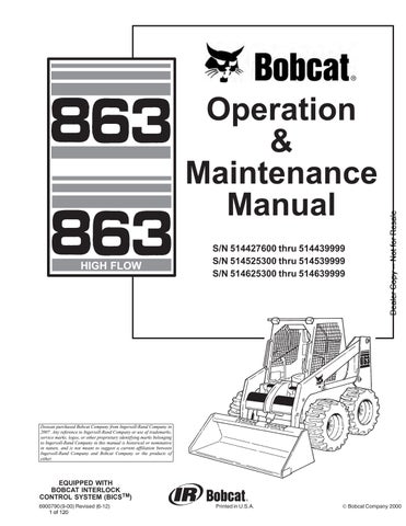
The following items are located on the BOSS Option Display Panel [A] & [(Item 8) [A] Page 4]: 10.a
1. FUEL LEVEL – Shows the amount of fuel in the tank. Flashing pump symbol indicateslow fuel level. H2O symbol is non–functional. (See WARNING SYMBOL )
2. BATTERY VOLTAGE – Shows the condition of the battery and charge rate. It will also indicate a WARNING for high or low voltage (See WARNING SYMBOL ).
3. ENGINE OIL PRESSURE – Shows engine oil pressure. Flashing symbol indicates low oil pressure (See WARNING and SHUTDOWN SYMBOL ).
4. ENGINE COOLANT TEMPERATURE/LEVEL –Shows engine coolant temperature (See WARNING and SHUTDOWN SYMBOL).
5. SHUTDOWN SYMBOL – This symbol is associated with any SHUTDOWN condition. When this symbol comes ON the SHUTDOWN will occur in 30 seconds. During SHUTDOWN the buzzer will sound continuously and the symbol will flash until the key switch is turned OFF.
NOTE:The engine can be restarted for 30–second periods to move the loader after a SHUTDOWN condition.
6. WARNING SYMBOL – The symbol will be ON when any WARNING or SHUTDOWN is activated. The warning symbol is also used to indicate a WARNING if there is no related symbol on the display. During a WARNING, the buzzer will beep three times and the symbol will be ON continuously.
7. HOURMETER – Records the total operating hours of the loader. The five character code will display the operating hours to the nearest tenth. When WARNING or SHUTDOWN occurs, an alpha–numeric code will be displayed in the hourmeter area to inform the operator of the problem (See SYSTEM ANALYSIS , Page 75). During a WARNING or SHUTDOWN the hourmeter symbol is not visible.
8. CHARGE PRESSURE AND FILTER CONDITION – Flashing symbol indicates low fluid charge pressure (See SHUTDOWN SYMBOL). If arrows are ON with gear/drop, it is fluid charge pressure. This symbol will also indicate a clogged hydraulic fluid filter.
9. AIR FILTER CONDITION – This symbol will indicate a clogged air filter element.
10. GLOW PLUG (Diesel) – The symbol will flash when the glow plugs are energized. The hourmeter will also contain characters GLOXX where XX indicates the remaining time the glow plugs will be ON. Time remaining will count down in 5 second increments.
11. ENGINE SPEED – This symbol will indicate an engine overspeed (See WARNING and SHUTDOWN SYMBOL)
12. PARKING BRAKE INDICATOR LIGHT (Non–Functional)
13. HYDRAULIC FLUID TEMPERATURE – This symbol will indicate a high fluid temperature. (See WARNING or SHUTDOWN SYMBOL above)
BOBCAT INTERLOCK CONTROL SYSTEM (BICS™)
The Bobcat Interlock Control System (BICS ™) requires the operator to be seated in the operating position with the Seat Bar fully lowered and the green PRESS TO OPERATE Button [B] activated before the lift, tilt and traction functions can be operated. The Seat Belt must be fastened anytime you operate the loader.
NOTE:Press the green PRESS TO OPERATE Button [B] again if Seat Bar is raised and lowered or key is turned off.
Avoid Injury Or Death
The Bobcat Interlock Control System (BICS) must deactivate the lift, tilt and traction drive functions. If it does not, contact your dealer for service. DO NOT modify the system.
W–2151–0394
The lift, tilt and traction drive functions are interlockedwith the Seat Bar.
The BICS Controller is located inside the cab; behind and to the right of the operator’s seat [A]

There are five green lights on the BICS Controller andall must be ON to operate the loader.
The light functions are as follows [A]:
1. SYSTEM ACTIVATED – ON when the green PRESS TO OPERATE Button is activated.
2. SEAT BAR – ON when the seat bar is in down position.
3. VALVE – ON when lift and tilt hydraulic functions can be used.
4. TRACTION – ON when loader can be moved forward or backward.
5. POWER – ON when the Controller is operating correctly.
NOTE:If any of the lights are off or blinking, see SERVICE CODES Page 77, BICS Troubleshooting Chart, Page 79, or see BICS Inspection and Maintenance Instructions Page 48.
BOBCAT INTERLOCK CONTROL SYSTEM (BICS™) (Cont’d)
Lift Arm By–Pass Control
The lift arm by–pass control knob (Item 1) [A] is used to lower the lift arms if the lift arms can not be lowered during normal operation.

With the operator in the seat, seat belt fastened and the seat bar fully lowered, turn the lift arm by–pass control knob (Item 1) [A] clockwise 1/4 turn. Then, pull up and hold the lift arm by–pass control until the lift arms slowly lower.
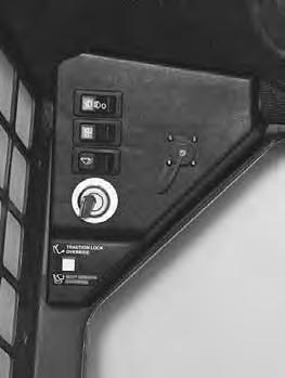
Traction Lock Override
6.
(Functions Only When The Seat Bar Is Raised) There is a Traction Lock Override button (Item 1) [B] on the left hand instrument panel which will allow you to use the steering levers to move the loader forward & backward when using the backhoe attachment or for loader service.
• Press the button once to unlock traction drive (green traction light on BICS Controller will be ON).
• Press the button a second time to lock the traction drive (green traction light on BICS Controller will be OFF).
NOTE:The Traction Lock Override button will unlock the traction drive when the operator is NOT in the seat and the seat bar is raised.


The Traction Lock Override button will function if brake pedal is in the engaged or disengaged position.
Auxiliary Hydraulic System (If Equipped)
When the operator is seated and raises the seat bar, the Auxiliary Hydraulic System will deactivate. Press the Auxiliary Hydraulics Switch (Item 1) [C] to reselect operating mode. (See Auxiliary Hydraulics Page 48.)
Traction Lock Control System
The Traction Lock Control System will lock the traction drive system when the engine stops.
NOTE:When the Traction Lock Override button is activated, the Traction Lock Control System will NOT engage the Traction Lock if the engine stops.
The Traction Lock Control System is incorporated into the BICS system. See BICS Inspection & Maintenance Page 48.
NOTE:The traction light on the BICS controller will remain OFF until the engine is started and if the parking brake is disengaged.
Engine Speed Control
The speed control lever (Item 1) [A] is at the right side of the operator’s seat. Engine speed is controlled by moving the lever forward to increase the engine RPM and backward to decrease the engine RPM.


Parking Brake
Engage the parking brake by pushing down on the top of the pedal [B]. The traction drive system will be locked. (See Traction Lock Override, Page 7.)
To release the parking brake, push down on the bottom of the pedal [C].
NOTE:If the loader will not move when operator is in the operating position with brake pedal released or when Traction Lock Override button is pushed, move the steering levers either forward or backward a small amount to unlock the traction drive.
Avoid Injury Or Death
When operating the machine:
• Keep the seat belt fastened snugly.
• The seat bar must be lowered.
• Keep your feet on the pedal controls or footrests.
W–2261–0397
The steering levers (Item 1) [A] are on the right and left side in front of the seat (foot pedal loader shown). Move levers smoothly. Avoid sudden starting and stopping.

The steering levers control forward and reverse travel and turning of the loader [B].
Forward Travel – Push both levers forward.
Reverse Travel – Pull both levers backward.
Normal Turning – Move one lever farther forward than the other.
Fast Turning – Push one lever forward and pull the other lever backward.
For slow travel speed, push the steering levers forward only a small amount.
To increase travel speed, push both levers farther forward.
For maximum pushing force, push the levers forward only a small amount with the engine at full RPM.
Stopping The Bobcat Loader
When the steering levers are moved to the neutral position the hydrostatic transmission will act as aservice brake to stop the loader.
Reverse
RIGHT TURN 863, 863H Bobcat Loader Operation & Maintenance Manual 9
Left Turn
SEAT BAR RESTRAINT SYSTEM (FOOT PEDALS)
The seat bar restraint system has a pivoting, spring assist seat bar (Item 1) [A] with arm rests and has spring loaded interlocks for the lift and tilt control pedals.
The operator controls the use of the seat bar. The seat bar in the down position helps to keep the operator in the seat.
The interlocks require the operator to lower the seat bar in order to operate the foot pedal controls.
When the seat bar is up, the lift and tilt control pedals are locked when returned to the NEUTRAL POSITION
Avoid Injury Or Death
When operating the machine:
• Keep the seat belt fastened snugly.
• The seat bar must be lowered.
• Keep your feet on the pedal controls.
W–2046–0595
Before you leave the operator’s seat:
• Lower the lift arms, put the attachment flat on the ground.
• Stop the engine.
• Engage the parking brake.
• Raise seat bar, move pedals until both lock.
W–2045–1086
The seat bar system must lock the lift and tilt control pedals in neutral when the seat bar is up. Service the system if pedals do not lock correctly.
W–2105–1285
The spring loaded interlocks (Item 1) [B] control the locking and unlocking functions of the Foot Pedal controls.
The interlocks (Item 1) [B] require the operator to lower the seat bar (Item 2) [B] which allows the operator to move the foot pedals to control the lift and tilt functions.
When the seat bar is lowered, it pushes the interlock (Item 1) [B] down on both sides, releasing the pedal linkages (Item 3) [B] from the interlocks.
The pedals will pivot in both directions when the interlock is down.
When the seat bar is raised, spring forces raise the interlocks [C].
The foot pedals will not pivot when the interlock is up.
See Page 45 for SEAT BAR RESTRAINT SYSTEM Inspection & Maintenance.
SEAT BAR RESTRAINT SYSTEM (MECHANICAL HAND CONTROLS)

The seat bar restraint system has a pivoting seat bar (Item 1) [A] with arm rests and has spring loaded interlocks for the lift and tilt control functions.
The operator controls the use of the seat bar. The seat bar in the down position helps to keep the operator in the seat.
The interlocks require the operator to lower the seat bar in order to operate the hand controls.
When the seat bar is up, the lift and tilt control functions are locked when returned to the NEUTRAL POSITION.
Avoid Injury Or Death
When operating the machine:
• Keep the seat belt fastened snugly.
• The seat bar must be lowered.
• Keep your feet on the foot rests.
W–2179–0694
Before you leave the operator’s seat:
• Lower the lift arms, put the attachment flat on the ground.
• Stop the engine.
• Engage the parking brake.
• Raise seat bar, move hand controls until both lock.
The seat bar system must lock the lift and tilt control in neutral when the seat bar is up. Service the system if hand controls do not lock correctly.
W–2153–0594
The spring loaded interlocks (Item 1) [B] control the locking and unlocking functions of the hand controls.
The interlocks (Item 1) [B] require the operator to lower the seat bar (Item 2) [B] which allows the operator to move the hand controls to control the lift and tilt functions.
When the seat bar is lowered, it pushes the interlock (Item 1) [B] down on both sides, releasing the hand control linkages (Item 3) [B] from the interlocks.
The hand controls will pivot in both directions when the interlock is down.
When the seat bar is raised, spring forces raise the interlocks [C].
The hand controls will not function when the interlock is up.
See Page 46 for SEAT BAR RESTRAINT SYSTEM Inspection & Maintenance.
SEAT BAR RESTRAINT SYSTEM (ADVANCED HAND CONTROLS)
The seat bar restraint system has a pivoting seat bar (Item 1) [A] with arm rests.
The operator controls the use of the seat bar. The seat bar in the down position helps to keep the operator in the seat.
When the seat bar is down, and the green PRESS TO OPERATE Button is activated, the lift, tilt, and traction drive functions can be operated.
When the seat bar is up, the lift, tilt, and traction drive functions are deactivated.
Avoid Injury Or Death
When operating the machine:
• Keep the seat belt fastened snugly.
• The seat bar must be lowered.
• Keep your feet on the foot rests.
W–2179–0694
Before you leave the operator’s seat:
• Lower the lift arms, put the attachment flat on the ground.
• Stop the engine.
• Engage the parking brake.
• Raise seat bar.
• Move the hand controls to the NEUTRAL POSITION to make sure that both lift and tilt functions are deactivated.
The seat bar system must deactivate the lift and tilt control functions when the seat bar is up. Service the system if hand controls do not deactivate.
W–2302–0698
See Page 47 for SEAT BAR RESTRAINT SYSTEM Inspection & Maintenance.
Hydraulic Controls
Foot Pedals
Keep both feet on pedals while operating machine. Failure to do so can cause serious injury.
W–2002–1285
Put your feet on the pedals and KEEP THEM THEREany time you operate the loader.
Two foot pedals (Item 1) [A] control the hydraulic cylinders for the lift and tilt functions.
Lift Arm Operation
The left pedal controls the lift arms. Push on the bottom (heel) (Item 2) [A] of the pedal to raise the lift arms.
Push on the top (toe) (Item 3) [A] of the pedal to lower the lift arms.
Lift Arm Float Position
Push the top (toe) (Item 3) [A] of the pedal all the way forward until it locks into the float position.
Use the float position of the lift arms to level loose material while driving backward.
Push the bottom (heel) of the lift pedal to unlock from the float position.
Tilt Operation
The right pedal controls the action of the bucket. Push the top (toe) (Item 4) [A] of the pedal to tilt the bucket forward.
Push the bottom of the pedal (heel) (Item 5) [A] to tilt the bucket backward.
Bucket Position Valve Operation (If Equipped)
The function of the bucket position valve is to keep the bucket in the same approximate position it is placed in, prior to the upward lift cycle.
Bucket positioning functions automatically during the upward lift cycle only.
The bucket positioning function (if equipped) can be turned OFF with the bucket level switch. (See Pages 3 & 4.)
HYDRAULIC CONTROLS (Cont’d)
Hand Controls (Mechanical and Advanced Hand Controls)
Keep both feet on footrests while operating machine. Failure to do so can cause serious injury.
W–2152–0594
Put your feet on the footrests and KEEP THEM THERE for comfort and safety any time you operate the loader.
Two hand levers [A] control the hydraulic cylinders for the lift and tilt functions.
Lift Arm Operation
The left hand lever controls the lift arms. Move the left hand lever away (Item 1) [A] from the operator to raise the lift arms.
Move the left hand lever toward (Item 2) [A] the operator to lower the lift arms.
Lift Arm Float Position
Move the left hand lever all the way toward the operator (Item 2) [A] until it locks into thefloat position.
Later AHC Models With Float Button
– Press anbd hold the Float Button (Item 5) [A] before moving the lever. – Press again to disengage.
Use the float position of the lift arms to level loose material while driving backward.
Move the left hand lever upward to unlockfrom the float position.
Tilt Operation
The right hand lever controls the action of the bucket. Move the right hand lever away (Item 3) [A] from the operator to tilt the bucket forward.
Move the right hand lever toward (Item 4) [A] the operator to tilt the bucket backward.
Bucket Position Valve Operation (If Equipped)
The function of the bucket positioning valve is to keep the bucket in the same approximate position it is placed in before beginning the upward lift cycle.
Bucket positioning functions automatically during the upward lift cycle only.
The bucket positioning function (if equipped) can be turned OFF with the bucket level switch. (See Page 3 and 4).
Advanced Hand Controls (AHC) (If Equipped)

AHC operation is the same as mechanical hand controls above.
Two lights (Item 1) [B] on the left handle are always ON when the AHC is functioning correctly. If lights are blinking or do not come ON , see Advanced Hand Controls
Troubleshooting Chart Page 79.
HYDRAULIC CONTROLS (Cont’d)
Auxiliary Hydraulics (If Equipped)
Avoid Burns
Hydraulic fluid, tubes, fittings and quick couplers can get hot when running machine and attachments. Be careful when connecting and disconnecting quick couplers.
W–2220–0396
NOTE:The loader has auxiliary proportional control for front auxiliary hydraulics only. Proportional control allows for slow–to–fast movement of auxiliary functions. EXAMPLE: If you move the auxiliary switch half way, the auxiliary function will move at approximately one–half speed.
Quick Couplers
To Connect: Remove any dirt or debris from the surface of both the male and female couplers, and from the outside diameter of the male coupler. Visually check the couplers for corroding, cracking, damage, or excessive wear. If any of these conditions exist, the coupler(s) must be replaced [A]

Install the male half coupler into the female coupler. Full connection is made when the ball release sleeve slides forward on the female coupler and the sleeve is rotated so that the locking pins (Item 1) [B] and the groove (Item 2) [B] do NOT align (Locked Position). This will prevent accidental disconnection.
NOTE: If the locking pins and grooves (Item 3) [C] are aligned, accidental disconnection is possible.
To Disconnect: Rotate the ball release sleeve so that the grooves are aligned with thepins (Item 3) [B] in the female coupler.
Hold the male coupler. Retract the sleeve on the female coupler until the couplers disconnect.

NOTE:Caps and plugs are not used with flush face couplers.
Relieving Hydraulic Pressure
7.
With the engine running, turn the key switch quickly to the left (counterclockwise) past the OFF position. Hold key for at least five seconds after the engine comes to a complete stop. This relieves pressure that can be trapped in the auxiliary circuit which would make it difficult to engage quick couplers from an attachment.
HYDRAULIC CONTROLS (Cont’d)
Auxiliary Hydraulics (Cont’d)
8. Auxiliary Hydraulics Switch


• Momentary Operation
Press the Auxiliary Hydraulics Switch (Item 1) [A] once.
The light (Item 2) [A] will be ON.
• Continuous Operation
Press the Auxiliary Hydraulics Switch (Item 1) [A] a second time.
Both lights (Items 2 & 3) [A] will be ON.
• Disengage
Press the Auxiliary Hydraulics Switch (Item 1) [A] a third time.
Both lights (Items 2 & 3) [A] will be OFF.
NOTE:When the operator is seated and raises the seat bar, the Auxiliary Hydraulic System (Front and Rear) will deactivate. Press the Auxiliary Hydraulics Switch (Item 1) [A] to reselect operating mode.
FRONT Auxiliary Hydraulics Operation (RIGHT Steering Lever)

• Set the Auxiliary Hydraulics Switch for Momentary Operation (See above).
• Push the switch (Item 1) [B] or [C] to the right or left to change the fluid flow direction to the front quick couplers. (EXAMPLE: Open and close grapple teeth.)
FRONT Auxiliary Hydraulics Continuous Operation (RIGHT Steering Lever)
• Set the Auxiliary Hydraulics Switch for Continuous Operation (See above).
• Push the front switch (Item 2) [B] or [C] to give the front quick couplers a constant flow of fluid (EXAMPLE: Operate a backhoe.)
• To release from continuous operation, press the front switch (Item 2) [B] or [C] a second time.

NOTE:The secondary front auxiliary hydraulics and the rear auxiliary hydraulics operate from the same auxiliary section of the control valve. To operate only one of these auxiliary functions, disconnect the other.
REAR Auxiliary Hydraulics Operation (LEFT Steering Lever)
• Set the Auxiliary Hydraulics Switch for Momentary or Continuous Operation (See above).

• Push the switch (Item 3) [B] or [C] to the right or left to change the fluid flow direction to the rear quick couplers [D]. (EXAMPLE: Raise and lower rear stabilizers.) This switch also controls the secondary front auxiliary. (Rear Auxiliary Hydraulics required)
NOTE:See System Analysis Page 75 for troubleshooting malfunctions with the Auxiliary Hydraulics Operation.
HYDRAULIC CONTROLS (Cont’d.)
Auxiliary Hydraulics (Cont’d.)
High–Flow Hydraulics Operation (If Equipped)
The High–Flow function provides additional flow to the system to operate an attachment which requires more hydraulic flow (EXAMPLE: Planer).
Continuous Operation
For continuous flow (through female coupler only). (See Page 16.)
Momentary Operation
For momentary operation. (See Page 16.)
• Be sure Hi–Flow switch is OFF
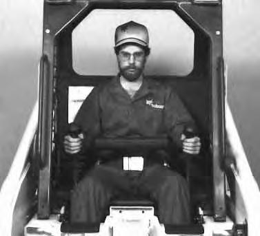
• Connect the attachment to the large quick couplers (Item 1) [A].
• Some attachments may have a case drain which needs to be the connected to the small quick coupler (Item 2) [A]

• When all hydraulic connections have been made, turn the Hi–Flow switch ON (Item 1)[B] (amber light is ON).
Secondary Front Auxiliary Hydraulics (If Equipped)
The secondary front auxiliary quick couplers are a part of the Hi–Flow Hydraulics (factory option) [A]. (Also available as a Field Installed Accessory.) These are used when there is a need for additional auxiliary hydraulics (EXAMPLE: Planer side shift).

• Connect the attachment to the secondary auxiliary hydraulics (Item 3) [A]
• Set the Auxiliary Hydraulic Switch for Momentary or Continuous Operation. (See Page 16.)


• Push switch (Item 1) [C] to the right or left to change fluid flow direction. (EXAMPLE: Side shift on the Planer.)

NOTE:The secondary front auxiliary hydraulics and the rear auxiliary hydraulics operate from the same auxiliary section of the control valve. To operate only one of these auxiliary functions, disconnect the other.
If the high–flow switch is in the ON position, High–Flow Hydraulics will flow through the front auxiliary quick couplers. Damage to unapproved attachments can result. Leave the switch OFF for backhoe operation.
I–2063–0295
HYDRAULIC CONTROLS (Cont’d.)
Attachment Functions Control (If Equipped)
(Attachment Control Kit Required) (Item 1) [A]
This kit, when installed, allows the use of other switches on the right and left control handles (Deluxe Handles) for functions such as water spray, left/right turn signals (Europe only), raise/lower the left/right ends of the moldboard on a Grader, etc.
The following are examples only, consult Attachment Operation & Maintenance Manual.
Switch (Item 1) [B] Left/Right Turn Signals . . .
Switch (Item 2) [B] Left Moldboard Up/Down . . .
Switch (Item 3) [B] Right Moldboard Up/Down
Switch (Item 4) [B] Water Spray . . .
DAILY INSPECTION
Maintenance work must be done at regular intervals. Failure to do so will result in excessive wear and early failures. The Service Schedule [C] is a guide for correct maintenance of the Bobcat loader. It is located inside the rear door of the loader and also in the MACHINE SIGN TRANSLATION Section Page 81.
Daily Inspection and Maintenance:
• Engine Oil Level
• Hydraulic/Hydrostatic Fluid Level
• Engine Air Filter, Air System for Damage or Leaks
• Engine Coolant Level, System for Damage or Leaks

• Operator Cab, Seat Belt, Seat Bar, Pedal Interlocks, & Hand Control Interlocks Mounting Hardware


• Grease Pivot Pins (Lift Arms, Bob–Tach, Cylinders, Bob–Tach Wedges
• Tires for Wear or Damage and Correct Air Pressure
• Fuel Filter, Remove Trapped Water
• Loose or Broken Parts
• Safety Treads and Safety Signs (Decals)
• Bobcat Interlock Control System (BICS ™)
• Lift Arm Support Device
NOTE:Fluids such as engine oil, hydraulic fluid, coolant, etc. must be disposed of in an environmentally safe manner. Some regulations require that certain spills and leaks on the ground must be cleaned in a specific manner. See local, state and federal regulations for correct disposal.
Diesel fuel or hydraulic fluid under pressure can penetrate skin or eyes, causing serious injury or death. Fluid leaks under pressure may not be visible. Use a piece of cardboard or wood to find leaks. Do not use your bare hand. Wear safety goggles. If fluid enters skin or eyes, get immediate medical attention from a physician familiar with this injury.
W–2072–0496
Getting Ready For Operation
Read and understand the Operation & Maintenance Manual and the Operator’s Handbook (Item 1) [A] before operating the loader.
The Operation & Maintenance Manual and other manuals can be kept in a box (Item 2)[A] provided at the right hand side of the operator seat.
Instructions are necessary before operating or servicing machine. Read and understand the Operation & Maintenance Manual, Handbook and signs (decals) on machine. Follow warnings and instructions in the manuals when making repairs, adjustments or servicing. Check for correct function after adjustments, repairs or service. Failure to follow instructions can cause injury or death.
W–2003–1298
Operator must have instructions before running the machine. Untrained operators can cause injury or death.

W–2001–0596
Use the bucket or attachment steps, grab handles and safety treads (on top of the loader lift arms and frame) to get on and off the loader [B]
Safety treads are installed on the Bobcatloader to provide a slip resistant surface for getting on and off the loader.
Keep safety treads clean and replace when damaged. Replacement treads are available from your Bobcat loader dealer.

GETTING READY FOR OPERATION (Cont’d.)
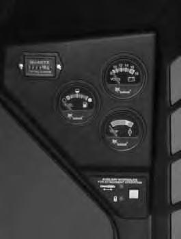
Pull the seat lever (Item 1)[A] and adjust the seat position for comfortable operation of the loader controls.

Fasten the seat belt snugly and adjust it so that the buckle is centered between your hips [B].
Avoid Injury Or Death
When operating the machine:
• Keep the seat belt fastened snugly.
• The seat bar must be lowered.
• Keep your feet on the pedal controls or footrests.
W–2261–0397
Lower the seat bar [B]
Be sure the parking brake is engaged.
All controls must be in the neutral positionbefore you start the engine.
After you start the engine, press the green PRESS TO OPERATE Button on the left instrument panel to operate lift, tilt and traction functions.
Foot Pedals: Keep your hands on the steering levers and feet on the foot pedals while seated in the loader [C]


Keep your hands on the steering levers and feet on the foot pedals or foot rests while seated in the loader [C].
Starting The Engine
When an engine is running in an enclosed area, fresh air must be added to avoid concentration of exhaust fumes. If the engine is stationary, vent the exhaust outside. Exhaust fumes contain odorless, invisible gases which can kill without warning [D].
W–2050–1285
AVOID INJURY OR DEATH
• Engines can have hot parts and hot exhaust gas. Keep flammable material away.
• Do not use machines in atmosphere containing explosive gas [D].
W–2051–1086