15 minute read
MAINTENANCE SAFETY

from Bobcat 853 & 853H Base Plus High Horsepower Loader Operation & Maintenance Manual - PDF DOWNLOAD

Instructions are necessary before operating or servicing machine, Read Operation & Maintenance Manual, Handbook and signs (decals) on machine. Follow warnings and instructions in the manuals when making repairs, adjustments or servicing. Check for correct function after adjustments, repairs or service. Failure to follow instructions can cause injury or death.
W–2003–1289
Safety Alert Symbol:This symbol is used for important safety messages. When you see this symbol, follow the safety message to avoid personal injury or death.
Correct
Correct
Correct
Never service the Bobcat® Skid Steer Loader without instructions.
Cleaning and maintenance are required daily. WRONG
Have good ventilation when welding or grinding painted parts. Wear dust mask when grinding painted parts. Toxic dust and gas can be produced.
Use the correct procedure to lift or lower operator cab with lift arms down.
Vent exhaust to outside when engine must be run for service. Avoid exhaust fume leaks which can kill without warning. Exhaust system must be tightly sealed.
Never work on loader with lift arms up unless lift arms are held by a lift arm support device. Never modify equipment or add attachments not approved by Melroe Company.
Wrong Wrong Wrong
Stop, cool and clean engine of flammable materials before checking fluids.
Never service or adjust loader with the engine running unless instructed to do so in the manual. Avoid contact with leaking hydraulic fluid or diesel fuel under pressure. It can penetrate the skin or eyes.
Never fill fuel tank with engine running, while smoking or when near open flame.
Keep body, jewelry and clothing away from moving parts, electrical contacts, hot parts and exhaust.
Wear eye protection to guard from battery acid, compressed springs, fluids under pressure and flying debris when engines are running or tools are used. Use eye protection approved for type of welding. Keep rear door closed except for service. Close and latch door before operating the loader.
Lead–acid batteries produce flammable and explosive gases. Keep arcs, sparks, flames and lighted tobacco away from batteries. Batteries contain acid which burns eyes or skin on contact. Wear protective clothing. If acid contacts body, flush well with water. For eye contact flush well and get immediate medical attention.
Maintenance procedures which are given in the Operation & Maintenance Manual can be performed by the owner/operator without any specific technical training. Maintenance procedures which are not in this manual must be performed ONLY BY QUALIFIED BOBCAT SERVICE PERSONNEL. Always use genuine Bobcat replacement parts.
Service Schedule
Maintenance work must be done at regular intervals. Failure to do so will result in excessive wear and early failures. The service schedule is a guide for correct maintenance of the Bobcat loader.
Instructions are necessary before operating or servicing machine. Read Operation Maintenance Manual, Handbook and signs (decals) on machine. Follow warnings and instructions in the manual when making repairs, adjustments or servicing. Check for correct function after adjustments, repairs or service. Failure to follow instructions can cause injury or death.
Engine Oil Check the oil level & add oil as needed.
Air Cleaner Check display or condition indicator. Service only when required.
Engine Cooling SystemClean debris from oil cooler, radiator & grill. Check coolant level cold in recovery tank. Add 50/50 ethylene glycol & water as needed.
Lift Arms, Cyl., Bob–TachLubricate with multipurpose lithium based grease (12 places).
Pivot Pins & Wedges
Engine Air System Check for leaks & damaged components.
Tires Check for damaged tires & correct air pressure.
Seat Belt, Seat Bar & PedalCheck the condition of seat belt. Check the seat bar & pedal Interlocks interlocks for correct operation. Clean dirt & debris from moving parts.
Safety Signs & SafetyCheck for damaged signs (decals) & safety tread. Replace any Tread signs or safety treads that are damaged or worn.
Operator Cab Check the fastening bolts, washers & nuts. Check the condition of cab.
Fuel Filter Remove the trapped water.
Hyd. Fluid, Hoses & Check fluid level & add as needed. Check for damage & leaks.
Tubelines Repair & replace as needed.
Final Drive Trans. Check oil level. (Chaincase)
Battery Check cables, connections & electrolyte level. Add distilled water as needed.
Control Pedals & SteeringCheck for correct operation. Repair or adjust as needed.
Wheel Nuts Check for loose wheel nuts & tighten to 105–115 ft.–lbs. (142–156 Nm) torque.
Parking Brake Check operation & adjust as needed.
Alternator Belt Check tension & adjust as needed.
Engine Oil & Filter Replace oil & filter.
Spark Arrestor MufflerClean the spark chamber.
Engine/Hydro. Drive BeltCheck for wear or damage. Make adjustment as needed.
Fuel Filter Replace filter element.
Seat Bar Grease pivots as needed.
Steering Shaft Grease two fittings.
Hyd./Hydro. Filter Replace the filter element.
Hyd. Reservoir BreatherReplace the reservoir breather cap. Cap
Fan Drive Gearbox Check gear lube level.
Final Drive Trans. Replace the oil in the chaincase.
Hyd. Reservoir Replace the fluid.
Hydraulic Motors Replace the case drain filters.
Check wheel nut torque every 8 hours for the first 24 hours. Also replace hydraulic/hydrostatic filter element when the transmission warning light comes ON. Or every 12 months.
*Inspect the new belt after first 50 hours. Clean or replace case drain filters in the event of any major hydraulic or hydrostatic repair.
Never work on a machine with the lift arms up unless the lift arms are secured by a lift arm support device. Failure to use an approved lift arm support device can allow the lift arms or attachment to fall and cause injury or death.
W–2059–0991
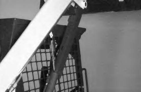
To Engage Lift Arm Support Device
Maintenance and service work can be done with the lift arms lowered. If the lift arms are raised use the following procedure:
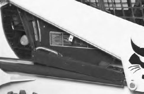
Put jackstands under the rear corners of the loader.
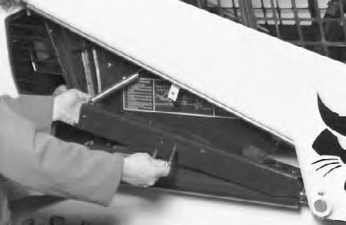
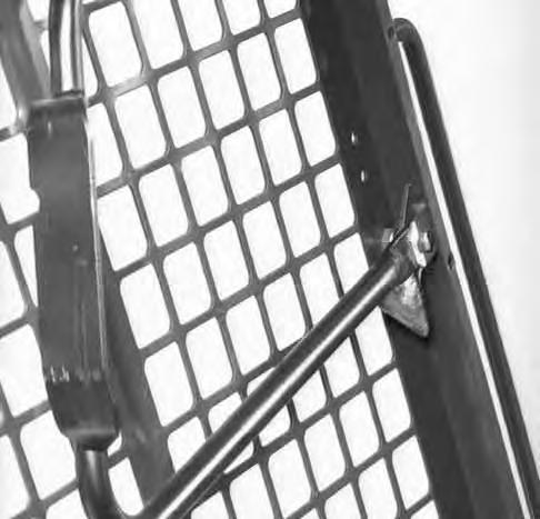
Disconnect the spring from the lift arm support device retaining pin and remove the retaining pin [A]
Lower the lift arm support device on top of the lift cylinder. Hook the free end of the spring to the lift arm support device so there will be no interference with the support device engagement.
With the operator in the seat, seat belt fastened and seat bar lowered, start the engine.
Raise the lift arms, until the lift arm support device drops onto the lift cylinder rod [C].
Lower the lift arms slowly until the support device is held between the lift arms and the lift cylinder. Stop the engine. Raise the seat bar and move the pedals until both pedals lock.
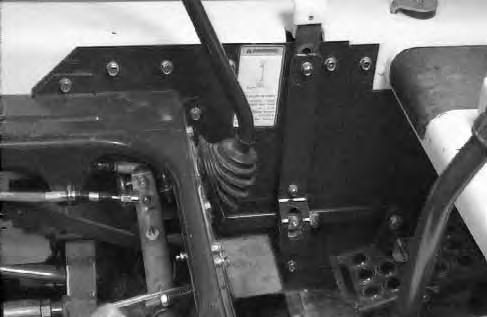
Install pin (Item 1) [C] into the rear of the lift arm support device below the cylinder rod.
To Disengage Lift Arm Support Device
Remove the pin from the lift arm support device. Connect the spring from the lift arm support device to the bracket below the lift arms [D]
With the operator in the seat, seat belt fastened and seat bar lowered, start the engine.
Raise the lift arms a small amount and the spring will lift the support device off the cylinder rod. Lower the lift arms. Stop the engine.
Raise the seat bar and move pedals until both pedals lock.
Disconnect the spring from the bracket.
Raise the support device into storage position and insert pin through lift arm support device and bracket [A].
Connect spring to pin [A]
Operator Cab
The Bobcat loader has an operator cab (ROPS and FOPS) as standard equipment to protect the operator from rollover and falling objects. Check with the dealer if the operator cab has been damaged.

Never modify operator cab by welding, grinding, drilling holes or adding attachments unless instructed to do so by Melroe Company. Changes to the cab can cause loss of operator protection from rollover and falling objects, and result in injury or death.
Raising The Operator Cab
Stop the loader on a level surface. Lower the lift arms. If the lift arms must be up while raising the operator cab, install the lift arm support device. (See LIFT ARM SUPPORT DEVICE Page 30.)
Before the cab or the lift arms are raised for service, jackstands must be put under the rear corners of the frame. Failure to use jackstands can allow the machine to tip backward causing injury or death.
Loosen the nut (both sides) at the front corner of the operator cab [A]
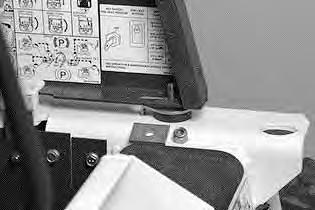
Remove the nut and plate (both sides) [B]
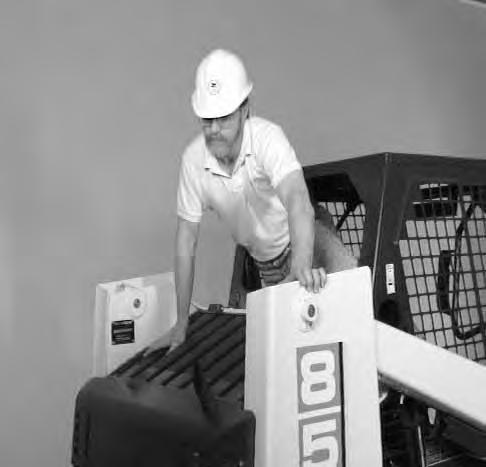
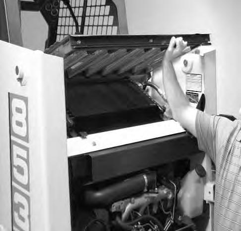
Lift on the grab handles and bottom of the operator cab slowly until the cab latching mechanism engages and the cab is all the way up [C]
Lowering The Operator Cab
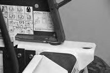
Pull down on the bottom of the operator cab until it stops on the latching mechanism. Release the latching mechanism (Item 1) [D] and pull the cab all the way down.
Install the plate and nut (both sides). Tighten the nuts to 40–50 ft.–lbs. (54–69 Nm) torque [A].
OPERATOR CAB (Cont’d)
Emergency Exit
The front opening on the operator cab and rear window provide exits.
To exit through the rear window, use the following procedure:
Pull on the tag at the rear window to remove the rubber cord [A]
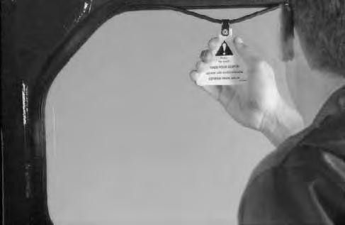
Push the rear window out of the rear of the operator cab. Exit through the rear of the operator cab [B]
Seat Bar Restraint System
The seat bar restraint system has pivoting seat bar with arm rests and has spring loaded interlocks for the lift and tilt control pedals. The operator controls the use of the seat bar. The seat bar in the down position helps keep the operator in the seat. The interlocks require the operator to lower the seat bar in order to operate the foot pedal controls. When the seat bar is up, the lift and tilt pedals are locked when returned to the neutral position.
AVOID INJURY OR DEATH
The seat bar system must lock the lift and tilt control pedals in neutral when the seat bar is up. Service the system if pedals do not lock correctly.
W–2105–1285
Seat Bar Inspection
Sit in the seat and fasten the seat belt. Engage the parking brake. Pull the seat bar all the way down. Start the engine. Operate each foot pedal to check both the lift and tilt functions. Raise the lift arms until the bucket is about 2 feet (600 mm) off the ground.
Raise the seat bar. Try to move each foot pedal. Pedals must be firmly locked in neutral position. There must be no motion of the lift arms or tilt (bucket) when the pedals are pushed.
Pull the seat bar down, lower the lift arms and place the bucket flat on the ground. Stop the engine. Raise the seat bar and operate the foot pedals to be sure that the pedals are firmly locked in the neutral position. Unbuckle the seat belt.
AVOID INJURY OR DEATH
Never operate loader without pedal lock shield 6705474 on both interlocks. Shields prevent foot from unlocking interlocks when leaving loader seat.
W–2162–1194
Seat Bar Maintenance
See the SERVICE SCHEDULE Page 29 and on the loader for correct service interval.
Clean any debris or dirt from the moving parts [A] & [B] Inspect the linkage bolts and nuts for tightness. The correct torque is 25–28 ft.–lbs. (34–38 Nm).
Use a general purpose grease to lubricate the seat bar pivot points at each side of the cab [A]. If the seat bar system does not function correctly, check for free movement of each linkage part. Check for excessive wear. Adjust pedal control linkage. Replace parts that are worn or damaged. Use only genuine Melroe replacement parts.
Avoid Injury
Never service or adjust the machine when the engine is running unless instructed to do so in the manual.
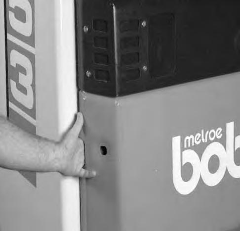
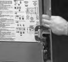
To open the rear door, use the following procedure: Put your fingers into the slot in the rear door and pull on the latch handle inside (Inset) [A] Pull the rear door open.
Keep the rear door closed when operating the machine. Failure to do so could seriously injure a bystander.
Adjustment
The door latch can be adjusted up or down for alignment with the door latch mechanism.
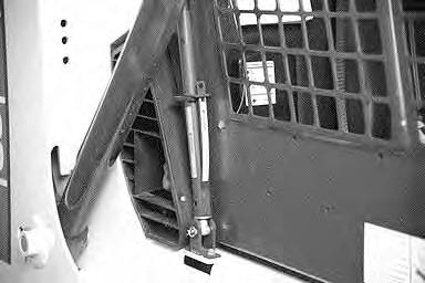
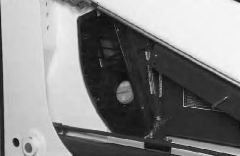
To open the rear grill, use the following procedure: Open the rear door.
Raise the rear grill [B].
The rear grill is held open by the cylinder (Item 1) [C].
NOTE:To prevent damage to the rear grill, always lower the rear grill before raising the operator cab.
Air Cleaner Service
853 Plus (5102), 853H Plus (5103)
It is important to change the air filter element only when the service code (on the instrument panel) shows the symbols as in the figure [A].
Service the air cleaner as follows:
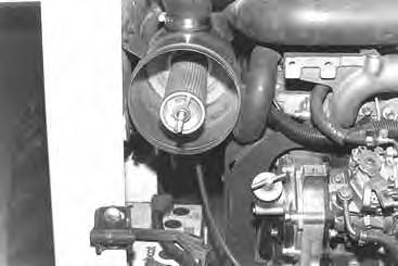
Remove the dust cover wing nut [B]
Remove the dust cover [C].
Remove the wing nut at the large filter element [D]
AIR CLEANER SERVICE (Cont’d)
853 Plus (5102), 853H Plus (5103) (Cont’d)
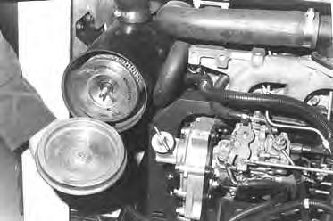
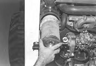
Remove the large filter element [A].
NOTE:Make sure all sealing surfaces are free of dirt and debris.
Install the new filter element and tighten the wing nut. Install the dust cover and tighten the wing nut.
NOTE:Make sure the evacuator is in the down position.
Check the air intake hose for damage. Check the air cleaner housing for damage. Check to make sure all connections are tight.
Only replace the inner filter element under the following conditions [B]:
1.Replace the inner filter element every third time the outer filter is replaced.
2.Replace the inner filter element when the service codes show symbols AF.2, only after the outer filter element has been changed and the engine speed is at full RPM.
853 Base (5101)
Replace the large (outer) filter element only when the red ring shows in the window of the condition indicator (Item 1) [C].
NOTE:Before replacing the filter element, push the button on the condition indicator (Item 2) [C], start the engine. If the red ring does not show, do not replace the filter element.
Replace the inner filter every third time the outer filter is replaced or when the red ring still shows in the indicator window after the outer filter has been replaced.
Fuel System
Fuel Specifications
Use only clean, high quality fuel. Use Grade No. 2 fuel above 40° F (4° C). Use Grade No. 1 fuel at temperatures below 40° F (4° C).
Filling The Fuel Tank
Stop and cool the engine before adding fuel. NO SMOKING! Failure to obey warnings can cause an explosion or fire.
W–2063–0887
Remove the fuel fill cap (Item 1) [A]
Use a clean, approved safety container to add fuel of the correct specifications. Add fuel only in an area that has free movement of air and no open flames or sparks. NO SMOKING! [B].
Install and tighten the fuel fill cap [A].
Fuel Filter
Always clean up spilled fuel or oil. Keep heat, flames, sparks or lighted tobacco away from fuel and oil. Failure to use care around combustibles can cause explosion or fire which can result in injury or death.
W–2103–1285
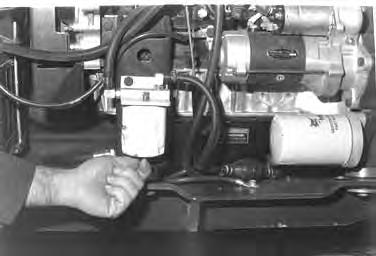
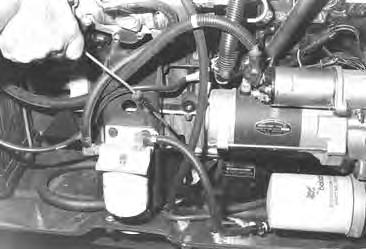
See the SERVICE SCHEDULE Page 29 for the service interval when to remove water from the fuel filter.
Loosen the drain at the bottom of the filter element to drain the water from the filter [C]
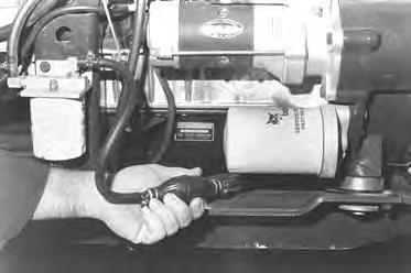
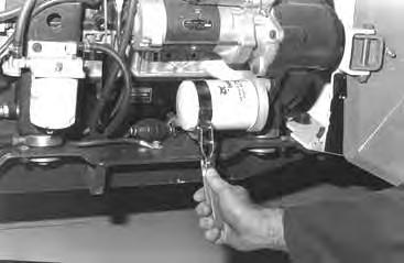
See the SERVICE SCHEDULE Page 29 for the service interval when to replace the fuel filter.
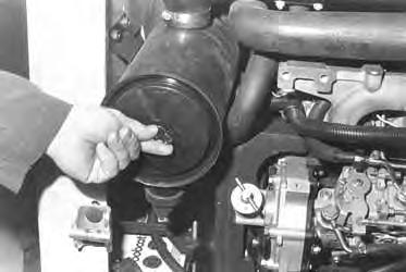
Use a filter wrench to remove the filter element [D].
Clean the area around the filter housing. Put oil on the seal of the new filter element. Install the fuel filter, hand tighten the filter element.
Remove the air from the fuel system. (See Removing Air From The Fuel System Page 38.)
FUEL SYSTEM (Cont’d)
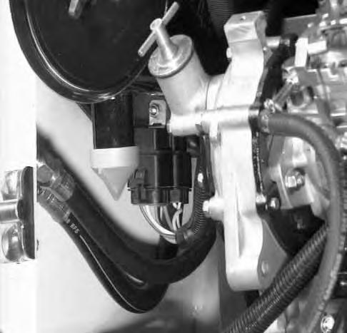
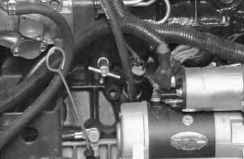
Removing Air From The Fuel System
After replacing the fuel filter element or when the tank has run out of fuel, the air must be removed from the fuel system to start the engine
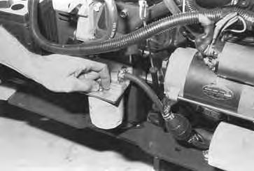
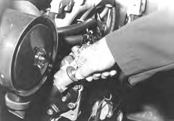
Loosen the air vent plug at the top of the fuel filter [A]
Operate the priming bulb until fuel flows from the filter vent plug [B]. Tighten the fuel filter vent plug.
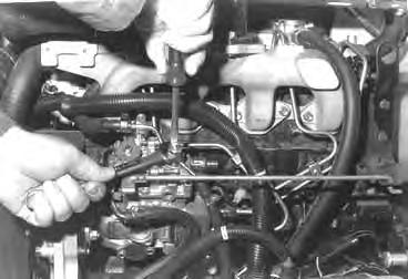
Loosen the air vent plug at the top of the fuel injection pump [C]
Again operate the priming bulb until fuel flows from the air vent plug with no air bubbles showing [B]
Tighten the air vent plug at the fuel injection pump [C]
Always clean up spilled fuel or oil. Keep heat, flames, sparks or lighted tobacco away from fuel and oil. Failure to use care around combustibles can cause explosion or fire which can result in injury or death.
Engine Lubrication System
Checking Engine Oil
Check the oil level every day.
Before starting the engine for the work shift, open the rear door remove the dipstick [A]
Keep the oil level between the marks on the dipstick. Use a good quality motor oil that meets API Service Classification of CC, CD or CE (See Oil Chart Below).
RECOMMENDED SAE VISCOSITY NUMBER (LUBRICATION OILS FOR ENGINE CRANKCASE)
TEMPERATURE RANGE ANTICIPATED BEFORE NEXT OIL CHANGE DIESEL: USE API CLASSIFICATION CC,CD or SE)
Replacing Oil And Filter
See the SERVICE SCHEDULE Page 29 for the service interval for replacing the engine oil and filter.
Run the engine until it is at operating temperature. Stop the engine.
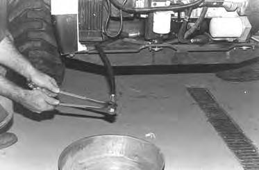
Open the rear door. Remove the drain plug [B]. Drain the oil into a container.
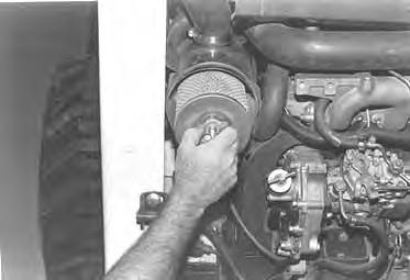
Remove the oil filter [C]
Clean the filter housing surface. Put clean oil on the oil filter gasket. Install the filter and hand tighten only. Install and tighten the drain plug.
ENGINE LUBRICATION SYSTEM (Cont’d)
Replacing
Oil And Filter (Cont’d)
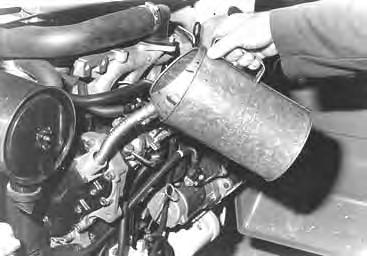
Remove the filler cap [A].
Put 8 qts. (7,6 L) of oil in the engine [B]. (See Checking Engine Oil Page 39.)
Start the engine and let it run for several minutes. Stop the engine. Check for leaks and check the oil level. Add oil as needed if not at the top mark on the dipstick.
Always clean up spilled fuel or oil. Keep heat, flames, sparks or lighted tobacco away from fuel and oil. Failure to use care around combustibles can cause explosion or fire which can result in injury or death.
W–2103–1285
Cooling System
Check the cooling system every day to prevent overheating, loss of performance or engine damage.
• When fluids are under pressure.
• Flying debris or loose material is present.
• Engine is running.
• Tools are being used.
Wear safety glasses to prevent eye injury when any of the following conditions exist: W–2019–1285
Cleaning The Cooling System
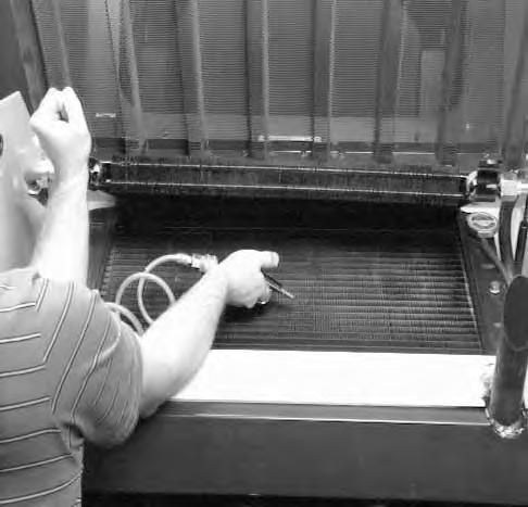
Raise the rear grill.
Use air pressure or water pressure to clean the top of the oil cooler [A]
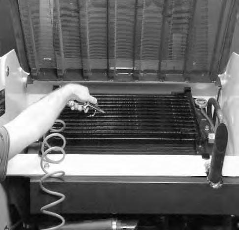
Raise the oil cooler and clean on the top of the radiator [B]
Check cooling system for leaks.
Checking The Coolant Level
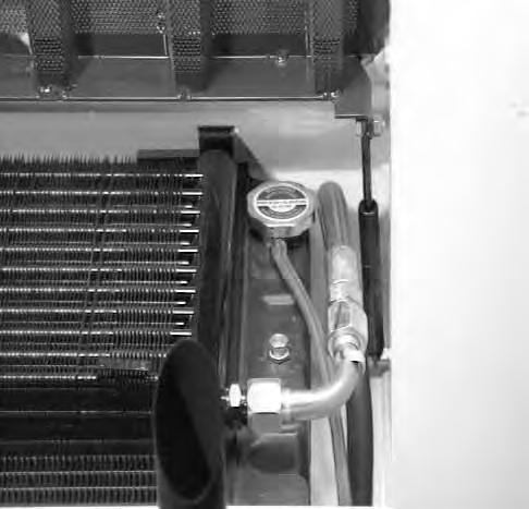
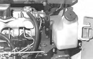
Open the rear door. Check the coolant level in the coolant recovery tank on the right side of the engine [C]
The coolant recovery tank must be 1/3 full (engine cold).
Add premixed coolant, 50% water and 50% ethylene glycol to the recovery tank if the coolant level is low.
COOLING SYSTEM (Cont’d)
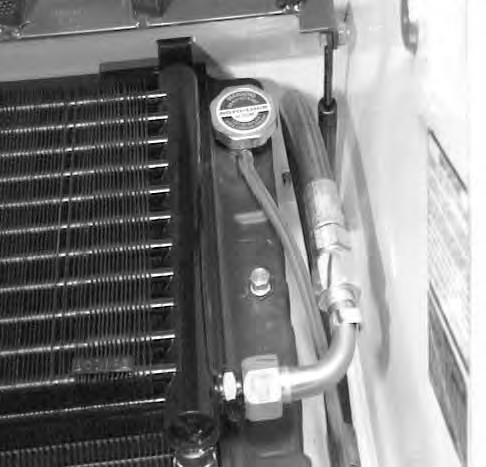
Removing Coolant From The Cooling System
Do not remove radiator cap when the engine is hot. You can be seriously burned.
Open the rear door. Open the rear grill.
Remove the radiator cap (Item 1) [A].
Install a hose on the petcock drain (Item 1) [B].
Open the petcock drain (Item 1) [B] and drain the coolant into a container.
After the coolant is removed, install and tighten the drain plug.
NOTE:Protect the cooling system by adding premixed 50% ethylene glycol and 50% water to the system. This mixture will protect the cooling system to –34° F (–36° C).
Mix the coolant in separate container. (See SPECIFICATIONS Page 69 for correct capacity.)
Fill the radiator and engine block with the premixed coolant. Install the radiator cap.
Fill the coolant recovery tank 1/3 full.
Run the engine until it is at operating temperature. Stop the engine. Check the coolant level in the recovery tank when cool. Add coolant to the recovery tank as needed.
Alternator Belt
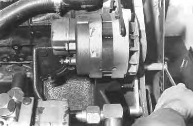
Adjusting The Alternator Belt
To adjust the belt tension for the alternator, use the following procedure:
Stop the engine.
Raise the operator cab. (See Raising The Operator Cab Page 31.)
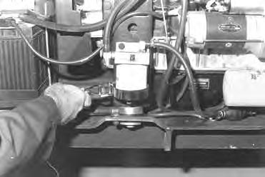
Loosen the alternator mounting bolt (Item 1) [A]
Loosen the adjustment bolt (Item 2) [A].
Move the alternator until the belt has 5/16 inch (8,0 mm) movement at the middle of the belt span with 15 lbs. (66 N) force.
ELECTRICAL SYSTEM Description
The loader has a 12 volt, negative ground alternator charging system. The electrical system is protected by fuses located in the instrument panel or the engine compartment. The fuses will protect the electrical system when there is an electrical overload. The reason for the overload must be found before starting the machine again.
Electrical System Service
The battery cables must be clean and tight. Check the water level in the battery. Remove any acid or corrosion from the battery and cables with a sodium bicarbonate and water solution [A]
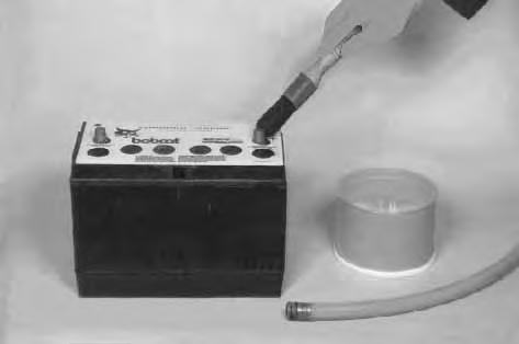
Cover the battery terminals and cable ends with grease.
Batteries contain acid which burns eyes and skin on contact. Wear goggles, protective clothing and rubber gloves to keep acid off body.
In case of acid contact, wash immediately with water. In case of eye contact get prompt medical attention and wash eye with clean, cool water for at least 15 minutes.
If electrolyte is taken internally drink large quantities of water or milk! DO NOT induce vomiting. Get prompt medical attention. W–2065–1296
Fuses
853 Plus (5102) & 853H Plus (5103)
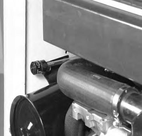
The electrical system for loaders is protected by two fuses (Item 1) [B] installed in the wiring harness. Fuses protect the electrical system from an overload. The fuses are located in the engine compartment under the air cleaner.
853 Base (5101)
The electrical system for this model loader is protected by two fuses (Item 1) [C] located in the instrument panel.