26 minute read
BEFORE OPERATING THE BOBCAT LOADER


Safety Alert Symbol
This symbol with a warning statement means: “Warning, be alert! Your safety is involved!” Carefully read the message that follows.
The Bobcat loader and attachment must be in good operating condition before use.
Check all of the items on the Bobcat Service Schedule Decal under the 8–10 hour column or as shown in this Manual.
SAFE OPERATION NEEDS A QUALIFIED OPERATOR *
A QUALIFIED OPERATOR MUST DO THE FOLLOWING:
• UNDERSTAND THE WRITTEN INSTRUCTIONS, RULES AND REGULATIONS
• The written instructions from Bobcat Company include the Delivery Report, Operation & Maintenance Manual, Operator’s Handbook, Safety Manual and machine signs (decals).
• Check the rules and regulations at your location. The rules may include an employer’s work safety requirements. Regulations may apply to local driving requirements or use of a Slow MovingVehicle (SMV) emblem. Regulations may identify a hazard such as a utility line.
• HAVE TRAINING WITH ACTUAL OPERATION
Operator must have instructions before running the machine. Untrained operators can cause injury or death.
Warnings on the machine and in the manuals are for your safety. Failure to obey warnings can cause injury or death. W–2044–1285
• Operator training must consist of a demonstration and verbal instruction. This training is given by your Bobcat dealer before the product is delivered.
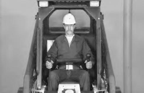
• The new operator must start in an area without bystanders anduse all the controls until he can operate the machine and attachment safely under all conditions of the work area. Always fasten seat belt before operating.
• Operator Training Courses are available from your Bobcat dealer in English and Spanish. They provide information for safe and efficient equipment operation. Safety videos are also available.
• Service Safety Training Courses are available from your Bobcat dealer. They provide information for safe and correct service procedures.
• KNOW THE WORK CONDITIONS
• Know the weight of the materials being handled. Avoid exceeding the Rated Operating Capacity of the machine. Material which is very dense will be heavier than the same volume of less dense material. Reduce the size of load if handling dense material.
• The operator must know any prohibited uses or work areas, for example, he needs to know about excessive slopes.
• Know the location of any underground lines. Call local utilities or the TOLL FREE phone number found in the SAFETY INSTRUCTIONS Section of this manual.
• Wear tight fitting clothing. Always wear safety glasses when doing maintenance or service. Safety glasses, hearing protection or special applications kit are required for some work.See your dealer about Bobcat Safety equipment.
* For an operator be qualified, he must not use drugs or alcoholic drinks which impair his alertness or coordination while working. An operator who is taking prescription drugs must get medical advice to determine if he can safely operate a machine.
SI02–0400
Fire Prevention
The machines and some attachments have components that are at high temperatures under normal operating conditions. The primary source of high temperatures is the engine and exhaust system. The electrical system, if damaged or incorrectly maintained, can be a source of arcs or sparks.
Flammable debris (leaves, straw, etc.) must be removed regularly. If flammable debris is allowed to accumulate, it can cause a fire hazard. Clean often to avoid this accumulation. Flammable debris in the engine compartment is a potential fire hazard.
The spark arrestor exhaust system (if equipped) is designed to control the emission of hot particles from the engine and exhaust system, but the muffler and the exhaust gases are still hot.
• Do not use the machine where exhaust, arcs, sparks or hot components can contact flammable material, explosive dust or gases.
• The operator cab, engine compartment and engine cooling system must be inspected every day and cleaned if necessary to prevent fire hazards and overheating.
• Check all electrical wiring and connections for damage. Keep the battery terminals clean andtight. Repair or replace any damaged part.
• Check fuel and hydraulic tubes, hoses and fittings for damage and leakage. Never use open flame or bare skin to check for leaks. Tighten or replace any parts that show leakage. Always clean fluid spills. Do not use gasoline or diesel fuel for cleaning parts. Use commercial nonflammable solvents.
• Do not use ether or starting fluids on any engine which has glow plugs. These starting aids can cause explosion and injure you or bystanders.
• Always clean the machine, disconnect the battery, and disconnect the wiring from the electronic controllers before welding. Cover rubber hoses, battery and all other flammable parts. Keep a fire extinguisher near the machine when welding. Have good ventilation when grinding or welding painted parts. Wear dust mask when grinding painted parts. Toxic dust or gas can be produced.
• Stop the engine and let it cool before adding fuel. No smoking!
• Use the procedure in the Operation & Maintenance Manual for connecting the battery and for jump starting.
• Use the procedure in the Operation & Maintenance Manual for cleaning the spark arrestor muffler (if equipped).
• Know where fire extinguishers and first aid kits are located and howto use them. Fire extinguishers are available from your Bobcat dealer.
MACHINE SIGNS (DECALS)
Follow the instructions on all the Machine Signs (Decals) that are on the loader. Replace any damaged machine signs and be sure they are in the correct locations. Machine signs are available from your Bobcat dealer.
MACHINE SIGNS (DECALS) (Cont’d)

INSTRUMENT PANEL (Standard)
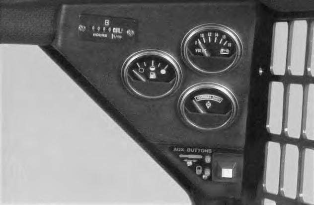
The following items are located on the standard instrument panel [A]:
1. KEY SWITCH – For starting and stopping the engine.
2. LIGHT SWITCH (OPT.) – Controls the work and travel lights.
3. FUSE (ACCESSORIES) – To protect the electrical system from overload.
4. FUSE (IGNITION) – To protect the electrical system from overload.
5. HOURMETER – Records the total operating hours of the loader.
6. VOLTMETER – Shows the condition of the battery and the rate of charge.
7. FUEL GAUGE – Shows the amount of fuel in the fuel tank.
8. ENGINE TEMPERATURE GAUGE – Shows the engine coolant temperature.
9. OPTIONAL AUXILIARY HYDRAULICS MODE SWITCH – For engaging the auxiliary hydraulics (front & rear).
10. PRE–HEAT BUTTON – For pre–heating the glowe plugs before starting the engine. (See Page 16.)
11. TRANSMISSION WARNING LIGHT– Low transmission charge pressure, hydraulic filter needs replacement or high fluid temperature. Stop the engine if the light comes ON.
12. ENGINE WARNING LIGHT – Engine oil pressure is low. Stop the engine if the light comes ON.
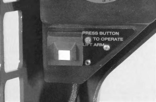
13. LIFT ARM OPERATION BUTTON – Lift arm operation button must be momentarily pressed after the seat bar is lowered and engine running to operate the lift arms. A green light will be ON when lift hydraulic system is activated.
INSTRUMENT PANEL (BOSS® Option)
The following items are located on the instrument panel [A] & [B]:
1. IGNITION SWITCH – Controls the starting and stopping of the engine. If engine doesn’t start turn the key to the OFF position for 3 seconds to reset the fuel timer module.
2. LIGHT SWITCH – Controls the work and travel lights.
3. DIAGNOSTIC COUPLER – Connector for diagnostic tool to make service checks of the system operation unit and other components.
4. DISPLAY PANEL – The display has the following symbols and functions (Ref. 7 thru 20).
5. OPTIONAL AUXILIARY HYDRAULICS MODE SWITCH – For engaging the auxiliary hydraulic (front and rear).
6. LIFT ARM OPERATION BUTTON – Lift arm operation button must be momentarily pressed after the seat bar is lowered and engine is running to operate the lift arms. A green light will be ON when the lift hydraulic system is activated.
7. FUEL – Shows the amount of fuel in the tank.
8. BATTERY VOLTAGE – Shows the condition of the battery and charge rate. Also will indicate a WARNING for high and low voltage.
9. ENGINE OIL SYMBOL – Shows engine oil pressure. Flashing symbol indicated low oil pressure.
10. ENGINE COOLANT SYMBOL – Shows engine coolant temperature and/or low coolant level (SHUTDOWN & WARNING).
11. FUEL FILTER – If fuel pump and bar flashes it is a low fuel WARNING H2O symbol indicates water in the fuel filter (NOT FUNCTIONAL AT THIS TIME).
12. SHUTDOWN SYMBOL – The symbol isassociated with any shutdown condition. When this symbol comes”ON” the shutdown will occur in 30 seconds. During shutdown the buzzer will sound continuously and the symbol will flash until the key is turned OFF.
NOTE:The engine can be restarted for 30–second periods to move the loader after a shutdown condition.
13. WARNING SYMBOL – The symbol will be ON when any warning or shutdown is activated. The warning symbol is also used to indicatea warning if there is no related symbol on the display. During a warning the buzzer will beep three times andsymbol will be on continuously.
14. HOURMETER – Records the total operating hours of the loader. The five character code will display the operating hours to the nearest tenth. When SHUTDOWNS or WARNINGS occur an alpha–numeric code will be displayed in the hourmeter area to inform the operator of the problem (See Page 58 for code listing). During a SHUTDOWN or WARNING the hourmeter symbol is not visible.
15. CHARGE PRESSURE AND FILTER CONDITION – Flashing symbol indicates low fluid charge pressure and SHUTDOWN. If arrows are ON with gear/drop it is fluid charge pressure.This symbol will also indicate a clogged hydraulic fluid filter.
16. AIR FILTER CONDITION – This symbol will indicate a clogged air filter element.
17. GLOW PLUG – The symbol will flashwhen the glow plus are energized. The hourmeter will also contain characters GLOXX where XX indicates the remaining time the glow plugs will be ‘‘ON’’. Glow plug will count down in 5 seconds increments.
18. ENGINE SPEED – This symbol will indicate an engine overspeed WARNING and SHUTDOWN.
19. PARKING BRAKE – This symbol will indicate when the brake is engaged (NOT FUNCTIONAL AT THIS TIME.
20. HYDRAULIC FLUID TEMPERATURE – This symbol will indicate a high fluid temperature and SHUTDOWN or WARNING.
Engine Speed Control
The lever (Item 1) [A] is at the right side of the operator’s seat. Engine speed is controlled by moving the lever forward to increase the engine RPM and backward to decrease the engine RPM.

Parking Brake
Lock the parking brake by pushing down on the top of the pedal [B]
To release the parking brake, push down on the bottom of the pedal [C].
Avoid Injury Or Death
When operating the machine:
• Keep the seat belt fastened snugly.
• The seat bar must be lowered.
• Keep your feet on the pedal controls.
W–2046–0595
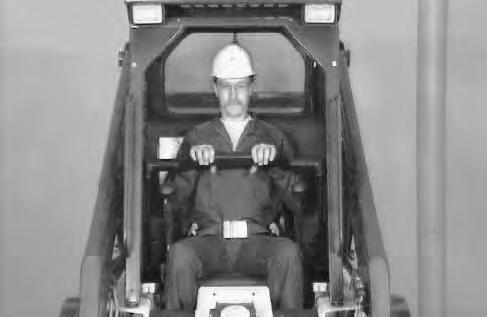
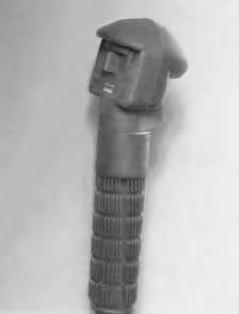
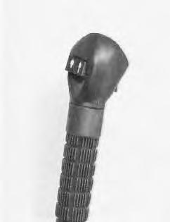
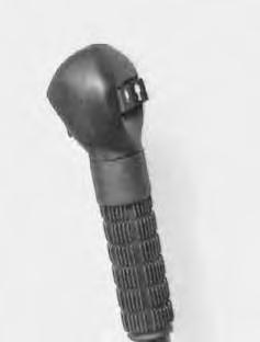
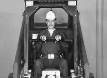
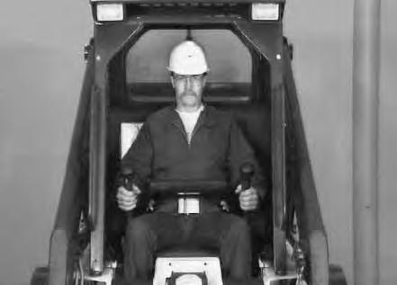
The steering lever (Item 1) [A] are on the right and left side in front of the seat.
For safe control of the loader always move the levers slowly and smoothly. Only a small movement is necessary to move the loader.
The steering levers control forward and reverse travel of the loader [B]
FORWARD TRAVEL – Push both levers forward.
REVERSE TRAVEL – Pull both levers backward.
NORMAL TURNING – Move one lever farther forward than the other.
FAST TURNING – Push one lever forward and pull the other lever backward.

For slow travel speed, push the steering levers forward only a small amount.
To increase travel speed, push both levers farther forward.
For maximum pushing force, push the levers forward only a small amount with the engine at full RPM.
Backward
Left Turn
RIGHT TURN 7753 Bobcat Loader Operation & Maintenance Manual –6–
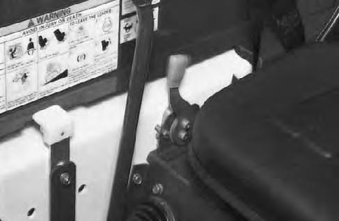
Lift Control System
Description
The Lift Control System contains a seat bar sensor, located in the left pivot of the seat bar. The sear bar must be lowered (all the way down) and the Lift Arm Operation Button momentarily pressed before the lift arm hydraulic system will be activated.
Operating the Lift Control System
1.Fasten the seat belt and lower the seat bar [A].
2.Start the engine (Page 14).
3.Momentarily press the Lift Arm Operation Button (Item 1) [B] to activate the lift hydraulic system a green light will be ON.
4.Operate lift control pedal as described (Page 9).
NOTE: Press the Lift Arm Operation Button again whenever the seat bar is raised and lowered or when the engine stops.
AVOID INJURY OR DEATH
The Lift Control System must deactivate the lift arm hydraulic system when the seat bar is raised. If the lift hydraulic system is NOT deactivated when the seat bar is fully raised, contact your dealer. DO NOT MODIFY THE SYSTEM.
W–2154–0594
AVOID INJURY OR DEATH
Before you leave the operator’s seat:
• Lower the lift arms, put the attachment flat on the ground.
• Stop the engine.
• Engage the parking brake.
• Raise seat bar, move pedals until both locked.
W–2045–1086
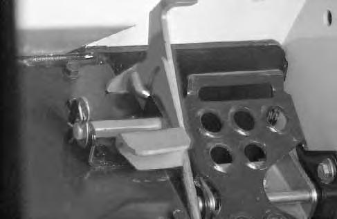
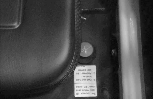
Lift Arm By–Pass Control
The by–pass control knob (Item 1)[C] is used to lower the lift arms in the event that the lift arms can not be lowered during normal operating conditions.
With the operator in the seat, seat belt fastened and the seat bar fully lowered, pull and hold the by–pass control knob (Item 1) [C] up. Push the top (toe) of the left (lift) pedal. The lift arms will slowly lower.

Seat Bar Restraint System
The seat bar restraint system hasa pivoting seat bar with arm rests and has spring loaded interlocks forthe lift and tilt control pedals. The operator controls the use of the seat bar. The seat bar in the down position helps to keep the operator in the seat. The interlocks require the operator to lower the seat bar in order to operate thefoot pedal controls. When the seat bar is up, the lift and tilt control pedals are locked when returned to the neutral position [A].
NOTE: Also See Page 7 for Lift Control System operation.
AVOID INJURY OR DEATH
When operating the machine:
• Keep the seat belt fastened snugly.
• The seat bar must be lowered.
• Keep your feet on the pedal controls.
W–2046–0595
The spring loaded interlocks (Item 1) [B] control the locking and unlocking functions of the control pedals.
The interlocks (Item 1) [B] require the operator to lower the seat bar (Item 2) [B] which allows the operator to move the foot pedals to control the lift and tilt functions.
When the seat bar is lowered, it pushes the interlock (Item 1) [B] down on both sides, releasing the pedal linkages (Item 3) [B] from the interlocks.
The pedals will pivot in both directions when the interlock is down.
AVOID INJURY OR DEATH
Before you leave the operator’s seat:
• Lower the lift arms, put the attachment flat on the ground.
• Stop the engine.
• Engage the parking brake.
• Raise seat bar, move pedals until both locked.
W–2045–1086
AVOID INJURY OR DEATH
The seat bar system must lock the lift and tilt control pedals in neutral when the seat bar is up. Service the system if pedals do not lock correctly.
W–2105–1285
When the seat bar is raised, spring forces raise the interlocks [C].
The foot pedals will not pivot when the interlock is up. Refer to the Preventive Maintenance section for Seat Bar Restraint System Inspection & Maintenance.
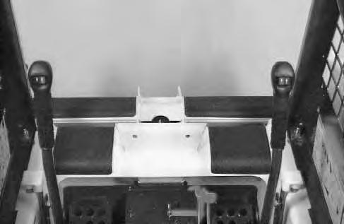
Hydraulic Controls
Foot Pedals
Keep both feet on pedals while operating machine. Failure to do so can cause serious injury.
Put your feet on the pedals and KEEP THEM THERE any time you operate the loader.
Two foot pedals (Item 1) [A] control the hydraulic cylinders for the lift and tilt function.
Lift Arm Operation
NOTE: Also See Page 7 for Lift Control System Operation.
The left pedal controls the lift arms. Push on the bottom (heel) (Item 2) [A] of the pedal to raise the lift arms.
Push on the top (toe) (Item 3)[A] of the pedal to lower the lift arms.
Push the top (toe) (Item 3) [A] of the lift pedal all the way forward until it locks into detent (float).
Use the float position of the lift arms to level loose material while driving backward.
Tilt Operation (Bucket)
The right pedal controls the action of thebucket. Push the top (toe) (Item 4)[A] of the pedal to tilt the bucket forward.
Push the bottom of the pedal (heel) (Item 5)[A] to tilt the bucket backward.
Bucket Position Valve (Optional)
The function of the bucket position valve is to keep the bucket in the same approximate position it is place in, prior to the upward lift cycle.
Bucket positioning functions automatically during the upward lift cycle only.
HYDRAULIC CONTROLS (Cont’d)
Auxiliary Hydraulics Operation (S/N 14348 & Above)
NOTE: Loaders starting at (S/N 30001) may be equipped as a standard or BOSS option machine. On loaders without a front and/or rear auxiliary option, the steering lever control handles will be blank (no switches).
Press the mode switch (Item 1) [A] or [B] (on the instrument panel) to allow for the front and rear auxiliary hydraulics, the light (Item 2) [A] or [B] will come ON.
The switch (Item 1)[C] on the right steering lever controls the front auxiliary hydraulics and the switch (Item 2)[C] on the left steering lever controls the rear auxiliary hydraulics.


Switch (Item 4) [C] controls the optional horn.
FRONT AUXILIARY CONTROL (OPTIONAL):
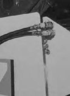
Push switch (Item 1) [C] in the right or left direction (with mode switch engaged & top light ON) to change fluid flow direction to the front quick couplers [D] (Example: Open and close grapple teeth).

REAR AUXILIARY CONTROL (OPTIONAL):
Push the switch (Item 2) [C] in the right or left direction (with mode switch engaged & toplight ON) to change the fluid flow direction to the rear quick couplers [D] (Example: Raise or lower rear stabilizers).
DETENT CONTROL:
Push the mode switch (Item 1)[A] or [B] the second time to engage the detent function and both lights (Items 2 & 3) [A] or [B] will come ON. Push the front button (Item 3) [C] to give the front auxiliary hydraulics a constant flow of fluid (Example: Operate a backhoe).
To release the detent position, push the switch (Item 3) [C] again.
RELIEVE PRESSURE AT FRONT QUICK COUPLERS:
Turn the key switch to the OFF position, as the engine stops running, turn the key switch all the way to the left (hold the key in this position until the engine stops) to release the hydraulic pressure at the front quick couplers.
RELIEVE PRESSURE AT REAR QUICK COUPLERS:
With the engine running, press the mode switch (Item 1) [A] or [B] to engage the auxiliary hydraulics, the light (Item 2) [A] or [B] will come ON.
Push the heel of the tilt pedal so the hydraulic fluid goes over the main relief pressure and at the same time push switch (Item 2) [C] to relieve the pressure at the rearquick couplers. Release the tilt pedals. Stop the engine.
HYDRAULIC CONTROLS (Cont’d)
Auxiliary Hydraulics Operation (S/N 14347 & Below)
Press the mode switch (Item 1) [A] (on the instrument panel) to engage the front and optional rear auxiliary hydraulics, the light (Item 2) will come ON.
The buttons (switches) (Items 1 & 2) [B] on the right steering lever control the front auxiliary hydraulics and the buttons (Items 3 & 4) [B] on the left steering lever control the optional rear auxiliary hydraulics.
FRONT AUXILIARY CONTROL:
Push either button (Items 1 or 2) [B] (with mode switch engaged & top light ON) to change fluid flow direction to the front quick couplers [C] (Example: Open and close grapple teeth).
REAR AUXILIARY CONTROL (OPTIONAL):
Push either button (Items 3 or 4) [B] (with mode switch engaged & top light ON) to change the fluid flow direction to the rear quick couplers [C] (Example: Raise or lower rear stabilizers).
DETENT CONTROL:
Push the mode switch (Item 1) [A] the second time to engage the detent function and both lights (Item 2 & 3) [A] will come ON. Push the front button (Item 5) [B] to give the front auxiliary hydraulics a constant flow of fluid (Example: Operate a backhoe).
To release the detent position, push the button (Item 5) [B] again.
RELIEVE PRESSURE AT FRONT QUICK COUPLERS:
Turn the key switch to the OFF position, as the engine stops running, turn the key switch all the way to the left (hold the key in this position until the engine stops) to release the hydraulic pressure at the front quick couplers.
RELIEVE PRESSURE AT REAR QUICK COUPLERS:
With the engine running, press the mode switch (Item 1) [A] to engage the auxiliary hydraulics, the light (Item 2) [A] will come ON.
Push the heel of the tilt pedal so the hydraulic fluid goes over the main relief pressure and at the same time push button (Items 3 & 4)[B] to relieve the pressure at the rear quick couplers. Release the tilt pedals. Stop the engine.
Daily Inspection
The loader must be in good operating condition [A].Check the following items:
• Engine Oil
• Hydraulic/Hydrostatic Fluid
• Engine Cooling System
• Operator Cab, Seat Belt, Seat Bar & Pedal Interlocks
• Lift Arm & Cylinder Pivot Pins
• Tires & Tire Pressure
• Any Loose or Broken Parts
• Safety Tread & Safety Signs
• Check the instrument panel display readout for faulty codes (Page 59).
• Lift Control System
Follow the maintenance requirements on the Service Schedule Decal, located inside the rear door [B].
Instructions are necessary before operating or servicing machine. Read Operation & Maintenance Manuals, Handbook and signs (decals) on machine. Follow warnings and instructions in the manuals when making repairs, adjustments or servicing. Check for correct function after adjustments, repairs or service. Failure to follow instructions can cause injury or death [A]. W–2003–1289
Getting Ready For Operation
Read the Operation & Maintenance Manual and the Operator’s Handbook before operating the loader [A]
Operator must have instructions before running the machine. Untrained operators can cause injury or death.
W–2001–1285
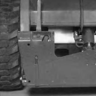
Use the bucket or attachment steps, grab handles and safety treads (on top of the loader lift arms and frame) to get on and off the loader [B]
Safety treads are installed on the Bobcatloader to provide a slip resistant surface for getting on and off the loader. Keep safety treads clean and replace when damaged. Replacement treads are available from your dealer.
Pull the seat lever (Item 1) and adjust the seat position for comfortable operation of the loader controls [C]
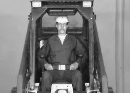

Fasten the seat belt snugly and adjust it so that the buckle is centered between the hips [D]
AVOID INJURY OR DEATH
When operating the machine:
• Keep the seat belt fastened snugly.
• The seat bar must be lowered.
• Keep your feet on the pedal controls.
W–2046–0595
GETTING READY FOR OPERATION (Cont’d)
Lower the seat bar [A]
Be sure the parking brake is engaged.All controls must be in the neutral position before you start the engine. (See Starting the Engine, Page 15–17.)
Starting The Engine
When an engine is running in an enclosed area, fresh air must be added to avoid concentration of exhaust fumes. If the engine is stationary, vent the exhaust outside. Exhaust fumes contain odorless, invisible gases which can kill without warning.
W–2050–1285
AVOID INJURY OR DEATH
• Engines can have hot parts and hot exhaust gas. Keep flammable material away.
• Do not use machines in atmosphere containing explosive gas.
W–2051–1086
STARTING THE ENGINE (Cont’d)
Adjust the seat position for comfortable operation of the foot pedals and steering levers.
Fasten the seat belt snugly and adjust it so the buckle is centered between the hips.
Lower the seat bar [A]
Put the foot pedals and steering levers in neutral (center) position (Item 1) [B]
Engage the parking brake.
Set the engine speed control to the mid position (Item 2) [B].
Normal Starting Condition (Standard)
Turn the key to the ON position,. The engine and transmission warning lights will be ON. When the key is on and the engine is stopped (Item 1) [C]
Turn the key to start position (Item 2) [C] and release it when the engine starts.
Do not engage the starter for longer than 15 seconds at a time. Longer use can damage the starter by overheating. Cool the starter for one minute between uses.
When the engine starts, release the key and it will return to the run poisition (Item 3) [C]
STOP THE ENGINE IF THE WARNING LIGHTS DO NOT GO OFF.
Without turning the key to the START position, turn the key to the RUN position (Item 3)[C] for starting theloader in the cold weather (See also Cold Temperature Starting Condition, Page 16).
NOTE: Upon failed start, if the key is turned OFF, wait for at least three seconds before turning the key ON to reset the fuel timer module.
STARTING THE ENGINE (Cont’d)
Cold Temperature Starting Condition (Standard)
See Normal Starting Condition, Page 15. Turn the key switch to the RUN position.
Push the PRE–HEAT button (Item 1) [A] on the left side of the instrument panel to pre–heat the glow plugs. Refer to the decal on the left side of the operator cab for operation of the pre–heat system [B]
Follow the steps under Normal Starting Condition and repeat the Pre–Heating procedure until the engine starts.
Do not use ether with glow plug (preheat) systems. Explosion can result which can cause injury or death.
If the temperature is below 32°F. (0°C.), use the following procedure to make starting the engine easier:
1.Replace the engine oil with the correct type and viscosity for the anticipated starting temperature (See Oil Chart, Page 37).
2.Make sure the battery is at full charge.
3.Install a block or tank heater on the engine.
Normal Starting Condition (BOSS® Option)
Turn the key to the ON position, one beep will sound and the display symbols will be ON[C]. Turn the key toSTART See Cold Temperature Starting Condition, Page 17.) Release the key when the engine starts.
Do not engage the starter for longer than 15 seconds at a time. Longer use can damage the starter by overheating. Cool the starter for one minute between uses.
When the key is turned ON, watch the alpha numeric display for readout codes. These readout codes are from the previous work shift when a WARNING may have occured (See Service Codes, Page 59 & 60).
The readout codes may be viewed again by turning the key switch OFF and then ON again without starting the engine.
Once the engine is started, the micro processor will clear all readout codes from memory. The codes will not reappear in subsequent key ON conditions unless the problem recurs.
NOTE:Upon failed start, if the key is turned OFF, wait for at least 3 seconds before turning the key ON to reset the fuel timer module.
STARTING THE ENGINE (Cont’d)
Cold Temperature Starting Condition (BOSS® Option)
Do not use ether with glow plug (preheat) systems. Explosion can result which can cause injury or death. W–2071–1285
See Normal Starting Condition, Page 16. Turn the key switch to the ON position (readout codes will show first) and the glow plug symbol will be ON [A].
NOTE: If display is showing readout codes the timing of the glow plug activation may be obscured on the display. However, the glow plugs will actually be energized.
The number display will indicate the characters GLOXX where XX will show remaining time the glow plugs willbe energized. The following chart shows the time glow plugs will be energized dependent on engine coolant temperature.
Turn the key to the START position and release when the engine starts. If the engine does not start, turn the key switch to the OFF position and ‘‘ON’’ again to cycle the glow plugs again. When the engine is running, slowly move the throttle forward to increase engine RPM.
If the starting temperature is below 32°F. (0°C.), use the following procedure to make starting easier:
1.Replace the engine oil with the correct type and viscosity for the anticipated starting temperature (See Oil Specifications Chart, Page 37).
2.Make sure the battery is at full charge.
3.Install an engine block heater or tank heater.
Warming the Hydraulic/Hydrostatic System
Let the engine run for a minimum of 5 minutes to warm the engine and hydrostatic fluid before operating the loader.
Stopping The Engine
Pull the engine speed control fully backward to decrease the engine RPM. Let the engine idle for several minutes. Turn the key switch to the OFF position.
When the temperature is below –20°F (–30°C), hydrostatic oil must be warmed before starting. The hydrostatic system will not get enough oil at low temperatures and will be damaged. Park the machine in an area where the temperature will be above 0°F (–18°C) if possible.
I–2007–1285
Never use attachments or buckets which are not approved by Bobcat Company. Buckets and attachments for safe loads of specified densities are approved for each model. Unapproved attachments can cause injury or death.
W–2052–1285
The dealer can identify, for each model loader, the attachments and buckets approved by BobcatCompany. The buckets and attachments are approved for Rated Operating Capacity and for secure fastening to the Bob–Tach.
The rated Operating Capacity for this loader is shown on a label in the operator cab. (See theSpecifications, Page 71.) It is determined by using a standard dirt bucket, and material of normal density, such as dirt or dry gravel. If longer buckets are used and load center moves forward and reduces the Rated Operating Capacity. If very dense material is loaded, the volume must be reduced.
Exceeding the Rated Operating Capacity can cause the following problems:
1.Steering the loader may be difficult.
2.Tires may wear faster.
3.There will be a loss of stability.
4.The life of the Bobcat loader will be reduced.
Use the correct size bucket for the type and density of material being handled. For safe handling of materials and avoiding machine damage, the attachment (or bucket) should handle a full load without going over the Rated Operating Capacity for the loader. Partial loads make steering more difficult.
Maximum loads to be carried when using a pallet fork are shown in figure [B].
Avoid Injury Or Death
Do not exceed rated operating capacity. Excessive load can cause tipping or loss of control.
W–2053–0887
WEIGHT OF LOADS LBS. (KG)
CENTER OF LOAD LOCATION Inches (mm)
ATTACHMENT AND BUCKETS (Cont’d)
Installation and Removal
The loader is equipped with the Bob–Tach system. The Bob–Tach is used for fast changing of buckets and attachments. See the Attachment Operator’s Manual to install other attachments.
Bob–Tach levers have spring tension. Hold lever tightly and release slowly. Failure to obey warning can cause injury.
W–2054–1285
Avoid Injury Or Death
Before you leave the operator’s seat:
• Lower the lift arms, put the attachment flat on the ground.
• Stop the engine.
• Engage the parking brake.
• Raise seat bar, move pedals until both locked.
W–2045–1086
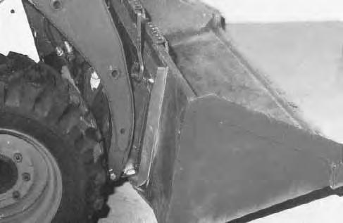
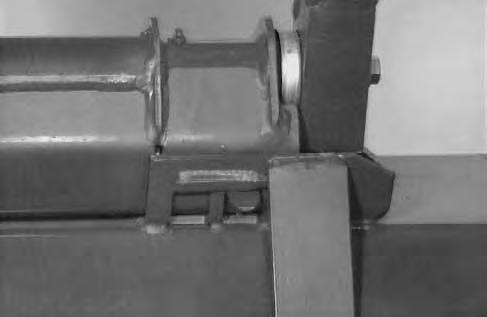
Pull the Bob–Tach levers all the way up.
Tilt the Bob–Tach forward. Drive the loader forward until the top edge of the Bob–Tach is completely under the flange of the bucket [A].
DO NOT hit the Bob–Tach levers on the bucket.
Tilt the Bob–Tach backward until the bucket is off the ground [B]. Stop the engine.
Push down on the Bob–Tach levers until they are in the locked position [C].
The wedges (Item 1) must extend through the holes in the bucket or attachment [D]
Bob–Tach wedges must extend through the holes in attachment. Levers must be fully down and locked. Failure to secure wedges can allow attachment to come off and cause injury or death.


W–2102–0588
Removal: Reverse the above procedure to remove the bucket or attachment from the Bob–Tach.
Operating Procedure
Always warm up the engine and hydrostatic system before operating the loader.
Machines warmed up with moderate engine speed and light load have longer life.
I–2015–0284
Operate the loader with the engine at full speed for maximum horsepower. Move the steering levers only a small amount to operate the loader slowly.
New operators must operate the loader in an open area without bystanders. Operate the controls until the loader can be handled at an efficient and safe rate for all conditions of the work area.
With a full bucket, go up to down the slope with theheavy end toward the top of the slope [A] & [B]
With empty bucket, go down or up the slope with the heavy end toward the top of the slope [C] & [D].
Avoid Injury Or Death
• Keep the lift arms as low as possible.
• Do not travel or turn with the lift arms up.
• Turn on level ground.
• Go up and down slopes, not across them.
• Keep the heavy end of the machine uphill.
• Do not overload the machine.
Failure to obey warnings can cause the machine to tip or roll over and cause injury or death.
W–2018–1187
Raise the bucket only high enough to avoid obstructions on rough ground.
OPERATING PROCEDURES (Cont’d)
Filling the Bucket
Push down on the top of the lift pedal until the lift arms are all the way down. Push the top of the tilt pedal to put the cutting edge of the bucket on the ground [A]
Load, unload and turn on flat level ground. Do not exceed rated operating capacity shown on sign (decal) in cab. Failure to obey warnings can cause the machine to tip or roll over and cause injury or death.
W–2056–1187
Drive slowly forward into the material. Push the bottom of the tilt pedal to raise the front of the bucket [B]
Drive backward away from the material.
Emptying the Bucket
Push down on the bottom of the lift pedal to raise the bucket over the truck box or bin [C]
Drive forward slowly until the bucket is over the top of the truck box or bin. Push the top of the tilt pedals until the bucket is empty [C]. If all the material is near the side of the truck or bin, push it to the other side with the bucket.
Never dump over an obstruction, such as a post, that can enter the operator cab. The machine could tip forward and cause injury or death.
W–2057–0694
OPERATING PROCEDURES (Cont’d) Digging Into the Ground
Put the lift arms all the way down. Push the top of the tilt pedal until the cutting edge of the bucket is on theground. Drive forward slowly and continue to tilt the bucket down until it enters the ground [A]
Push the bottom of the tilt pedal a small amount to increase traction and keep an even digging depth. Continue to drive forward until the bucket is full. Whenthe ground is hard, raise and lower the cutting edge of the bucket with the tilt pedal while driving forward slowly.
Push the bottom of the tilt pedal to tiltthe bucket backward as far as it will go when the bucket is full [B]
Leveling the Ground (Using Lift Arms in Float Position)
Push the top (toe) of the lift pedal all the way forwarduntil the pedal is in the locked position (detent) to put the lift arms in a float position [C]
Push the tilt pedal to change the position of the cutting edge on the bucket. With the bucket tilted farther forward, there is more force on the cutting edge and more loose material can be moved.
Never drive forward when the hydraulic control for lift arms is in float position.
Drive backward to level loose material. Push the bottom of the lift pedal to unlock from the detent position.
OPERATING PROCEDURES (Cont’d)
Backfilling
Lower the lift arms and put the cutting edge of the bucket on the ground. Drive forward to the edge of the hole to push the material into the hole [A].
Tilt the bucket forward as soon as it is past the edge of the hole [A]
If necessary, raise the lift arms to empty the bucket.
Parking The Bobcat Loader
1.Stop the Bobcat loader on level ground.
2.Lower the lift arms fully and put the attachment flat on the ground.
3.Pull the engine speed control lever all the way backward. Turn the key switch to the OFF position.
Avoid Injury Or Death
Before you leave the operator’s seat:
• Lower the lift arms, put the attachment flat on the ground.
• Stop the engine.
• Engage the parking brake.
• Raise seat bar, move pedals until both locked.
W–2045–1086
4.Engage the parking brake.
5.Lift the seat bar and make sure the foot pedals are in the locked position.
6.Un–buckle the seat belt. Remove the key from the switch to prevent operation of the loader by unauthorized personnel.
Adequately designed ramps of sufficient strength are needed to support the weight of the machine when loading onto a transport vehicle. Wood ramps can break and cause personal injury.
A loader with an empty bucket or no attachment must be loaded backward onto the transport vehicle [A]
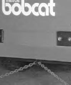
Use the following procedure to fasten the Bobcat loader to the transport vehicle to prevent the loader from moving during sudden stops or when going up or down slopes.
1.Lower the bucket or attachment to the floor. Stop the engine.
2.Engage the parking brake.
3.Install chains and chain binders at the front and rear of the loader [B].

SINGLE POINT LIFT
AVOID INJURY OR DEATH
• BEFORE LIFTING, CHECK FASTENERS ON SINGLE POINT LIFT AND OPERATOR CAB.
• ASSEMBLE FRONT CAB FASTENERS AS SHOWN IN MANUAL.
• NEVER ALLOW RIDERS IN THE CAB OR BYSTANDERS WITHIN 15 FEET (5 METERS) WHILE LIFTING THE MACHINE.
The loader can also be lifted with the singlepoint lift which is available as a kit from your Bobcat loader dealer. Install the kit and lift as shown [C]
The single point lift, supplied by Bobcat Company is designed to lift and support the Bobcat loader without affecting roll over and falling object protection features of the operator cab.