27 minute read
INSTRUMENT PANEL (Cont’d)


1. FUEL LEVEL – Shows the amount of fuel in the tank. Flashing pump symbol indicates low fuel level. (H2O symbol is non–functional.) (See WARNING SYMBOL)
2. BATTERY VOLTAGE – Shows the condition of the battery and charge rate. It will also indicate a WARNING for high or low voltage (See WARNING SYMBOL ).
3. ENGINE OIL PRESSURE – Shows engine oil pressure. Flashing symbol indicates low oil pressure (See WARNING and SHUTDOWN SYMBOL ).
4. ENGINE COOLANT TEMPERATURE / LEVEL –Shows engine coolant temperature and/or low coolant level (See WARNING and SHUTDOWN SYMBOL )
5. SHUTDOWN SYMBOL – This symbol is associated with any SHUTDOWN condition. When this symbol comes ON the SHUTDOWN will occur in 30 seconds. During SHUTDOWN the buzzer will sound continuously and the symbol will flash until the key switch is turned OFF.
NOTE:The engine can be restarted for 30–second periods to move the loader after a SHUTDOWN condition.
6. WARNING SYMBOL – The symbol will be ON when any WARNING or SHUTDOWN is activated. The warning symbol is also used to indicate a WARNING if there is no related symbol on the display. During a WARNING, the buzzer will beep three times and the symbol will be ON continuously.
7. HOURMETER – Records the total operating hours of the loader. The five character code will display the operating hours to the nearest tenth. When WARNING or SHUTDOWN occurs, an alpha–numeric code will be displayed in the hourmeter area to inform the operator of the problem (See SYSTEMS ANALYSIS , Page 79). During a WARNING or SHUTDOWN the hourmeter symbol is not visible.
8. CHARGE PRESSURE AND FILTER CONDITION – Flashing symbol indicates low fluid charge pressure (See SHUTDOWN SYMBOL). If arrows are ON with gear/drop, it is fluid charge pressure. This symbol will also indicate a clogged hydraulic fluid filter.
9. AIR FILTER CONDITION – This symbol will indicate a clogged air filter element.
10. GLOW PLUG (Diesel) – The symbol will be ON when the glow plugs are energized. The hourmeter will also contain characters GLOXX where XX indicates the remaining time the glow plugs will be ON. Time remaining will count down in increments.
11. ENGINE SPEED – This symbol will indicate an engine overspeed (See WARNING and SHUTDOWN SYMBOL).
12. PARKING BRAKE INDICATOR LIGHT (Non–Functional) .
13. HYDRAULIC FLUID TEMPERATURE – This symbol will indicate a high fluid temperature. (See WARNING or SHUTDOWN SYMBOL above).
BOBCAT INTERLOCK CONTROL SYSTEM (BICS™)
The Bobcat Interlock Control System (BICS™) requires the operator to be seated in the operating position with the seat bar fully lowered before the lift, tilt and traction functions can be operated. The seat belt must be fastened anytime you operate the loader.
Avoid Injury Or Death
The Bobcat Interlock Control System (BICS) must deactivate the lift, tilt and traction drive functions. If it does not, contact your dealer for service. DO NOT modify the system.
W–2151–0394
The lift, tilt and traction drive functions are interlocked with the seat bar. The lift and tilt functions are interlocked with the seat.
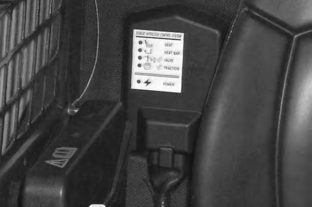
The BICS controller is located inside the cab; behind and to the right of the operator’s seat [A]
There are five green lights on the BICS controller and all must be ON to operate the loader.
The light functions are as follows [A]:
1. SEAT – ON when operator is in the seat.
2. SEAT BAR – ON when the seat bar is in down position.
3. VALVE – ON when lift and tilt hydraulic functions can be used.
4. TRACTION – ON when loader can be moved forward or backward.
5. POWER – ON when the controller is operating correctly.
NOTE:If any of the lights are off or blinking, see BICS Troubleshooting Chart Page 82, orsee BICS Inspection and Maintenance Instructions Page 49.
BOBCAT INTERLOCK CONTROL SYSTEM (BICS™) (Cont’d)
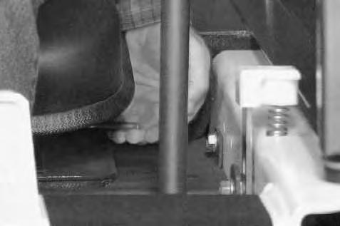
Lift Arm By–Pass Control
Use the lift arm by–pass control knob (Item 1) [A] to lower the lift arms if the lift arms can not be lowered during normal operation.
With the operator in the seat, seat belt fastened and the seat bar fully lowered, turn the lift arm by–pass control knob (Item 1) [A] clockwise 1/4 turn. Then, pull up and hold the lift arm by–pass control until the lift arms slowly lower.
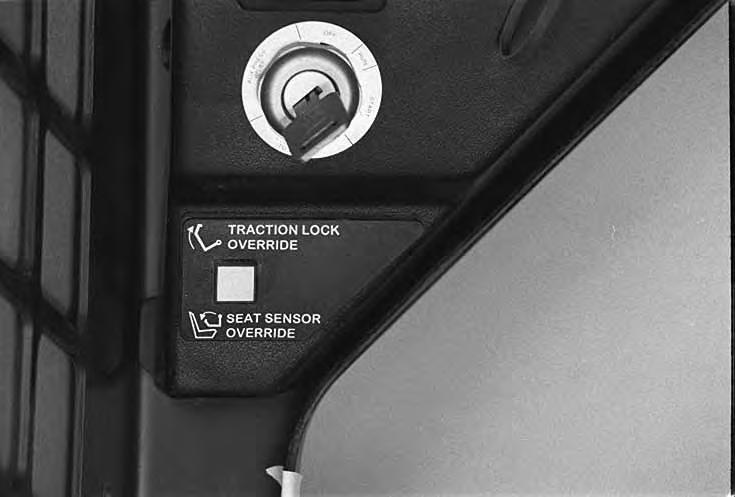
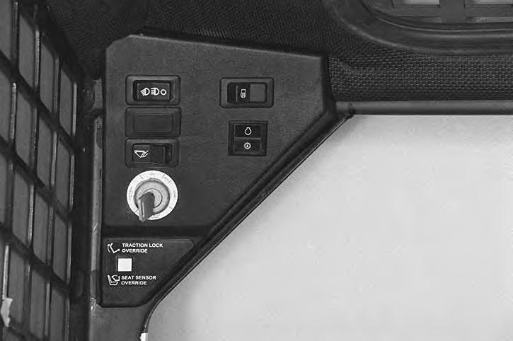
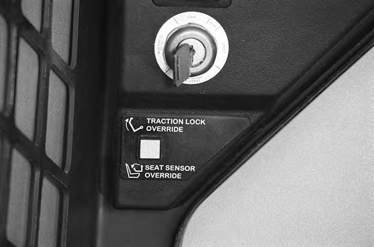
Traction Lock Override
(Functions Only When The Seat Bar Is Raised)
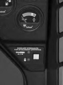
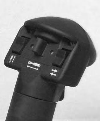
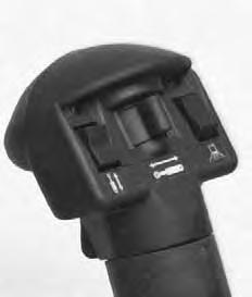
There is a traction lock override button (Item 1) [B] on the left hand instrument panel which will allow you to use the steering levers to move the loader forward & backward when using the backhoe attachment or for loader service.
• Press the button once to unlock traction drive (green traction light on BICS controller will be ON).
• Press the button a second time to lock the traction drive (green traction light on BICS controller will be OFF).
NOTE:The traction lock override button will unlock the traction drive when the operator is NOT in the seat and the seat bar is raised.
The traction lock override button will function if brake pedal is in the engaged or disengaged position.
Seat Sensor Override (If Equipped)
(Functions Only When The Seat Bar Is Down)
Seat Sensor Override button (Item 1) [B] allows operator, when seated with the seat bar lowered, to use lift, tilt, and traction functions if the seat sensor cannot be activated.
If seat indicator light on the BICS Controller does not go on, check for debris, dirt, or objects under or behind seat.
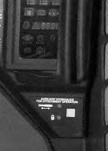
Auxiliary Hydraulic System
When the operator is seated and raises the seat bar, the Auxiliary Hydraulic System will deactivate. Press the Auxiliary Hydraulics Switch (Item 1) [C] to reselect operating mode. (See HYDRAULIC CONTROLS, Auxiliary Hydraulics Page 15.)
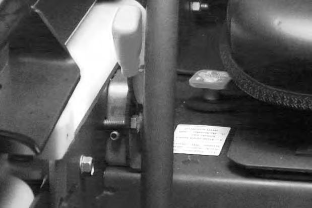
Engine Speed Control
The speed control lever (Item 1) [A] is at the right side of the operator’s seat.

Change the engine speed by moving the lever forward to increase the engine RPM and backward to decrease the engine RPM.
Parking Brake
Engage the parking brake by pushing down on the top of the pedal [B]. The traction drive system will be locked. (See Traction Lock Override Page 7.)
Release the parking brake by pushing down on the bottom of the pedal [C]
NOTE:If the loader will not move when operator is in the operating position with brake pedal released or when traction lock override button is pushed, move the steering levers either forward or backward a small amount to unlock the traction drive.
Avoid Injury Or Death
When operating the machine:
• Keep the seat belt fastened snugly.
• The seat bar must be lowered.
• Keep your feet on the pedal controls or footrests.
W–2261–0397
The steering levers (Item 1) [A] are on the left and right side in front of the seat.

For safe control of the loader always move the levers slowly and smoothly. Only a small movement is necessary to move the loader.
The steering levers control forward and reverse travel and turning of the loader [B]
Forward Travel – Push both levers forward.
Reverse Travel – Pull both levers backward.
Normal Turning – Move one lever farther forward than the other.
Fast Turning – Push one lever forward and pull the other lever backward.
For slow travel speed, push the steering levers forward only a small amount.
To increase travel speed, push both levers farther forward.
For maximum pushing force, push the levers forward only a small amount with the engine at full RPM.
Stopping The Bobcat Loader
Move the steering levers to the NEUTRAL POSITION. The hydrostatic transmission will act as a service brake to stop the loader.
RIGHT TURN A P–04132
REVERSE 1 Operation & Maintenance Manual –9–753 Bobcat Loader
Left Turn
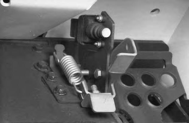
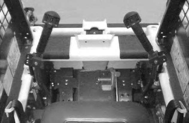
SEAT BAR RESTRAINT SYSTEM (FOOT PEDALS)
The seat bar restraint system has a pivoting , spring assist seat bar (Item 1) [A] with arm rests and has spring loaded interlocks for the lift and tilt control pedals.
The operator controls the use of the seat bar. The seat bar in the down position helps to keep the operator in the seat.

The interlocks require the operator to lower the seat bar in order to operate the foot pedals.
When the seat bar is up, the lift and tilt foot pedals are locked when returned to the NEUTRAL POSITION.
Avoid Injury Or Death
When operating the machine:
• Keep the seat belt fastened snugly.
• The seat bar must be lowered.
• Keep your feet on the pedal controls or footrests.
W–2261–0397
The spring loaded interlocks (Item 1) [B] control the locking and unlocking functions of the foot pedals.
The interlocks (Item 1) [B] require the operator to lower the seat bar (Item 2) [B] which allows the operator to move the foot pedals to control the lift and tilt functions.
When the seat bar is lowered, it pushes the interlock (Item 1) [B] down on both sides, releasing the pedal linkages (Item 3) [B] from the interlocks.
The foot pedals will pivot in both directions when the interlock is down.
Before you leave the operator’s seat:
• Lower the lift arms, put the attachment flat on the ground.
• Stop the engine.
• Engage the parking brake.
• Raise seat bar.
• (Foot Pedal Controls) Move pedals until both lock.
W–2328–0798
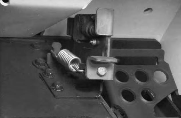
When the seat bar is raised, spring forces raise the interlocks [C].
The foot pedals will not pivot when the interlock is up. Refer to Seat Bar Restraint System Inspection & Maintenance Page 49 or 50.
SEAT BAR RESTRAINT SYSTEM (MACHANICAL HAND CONTROLS)
The seat bar restraint system has a pivoting seat bar (Item 1) [A] with arm rests and has spring loaded interlocks for the lift and tilt control functions.
The operator controls the use of the seat bar. The seat bar in the down position helps to keep the operator in the seat.
The interlocks require the operator to lower the seat bar in order to operate the hand controls.
When the seat bar is up, the lift and tilt control functions are locked when returned to the NEUTRAL POSITION.
Avoid Injury Or Death
When operating the machine:
• Keep the seat belt fastened snugly.
• The seat bar must be lowered.
• Keep your feet on the footrests.
W–2179–0694
The spring loaded interlocks (Item 1) [B] control the locking and unlocking functions of the hand controls.
The interlocks (Item 1) [B] require the operator to lower the seat bar (Item 2) [B] which allows the operator to move the hand controls to control the lift and tilt functions.
When the seat bar is lowered, it pushes the interlock (Item 1) [B] down on both sides, releasing the hand control linkages (Item 3) [B] from the interlocks.
The hand controls will pivot in both directions when the interlock is down.
Before you leave the operator’s seat:
• Lower the lift arms, put the attachment flat on the ground.
• Stop the engine.
• Engage the parking brake.
• Raise seat bar.
• (Mechanical Hand Controls) Move the hand controls until both lock. The seat bar system must lock the lift and tilt controls in neutral when the seat bar is up. Service the system if hand controls do not lock correctly.
W–2322–0698
When the seat bar is raised, spring forces raise the interlocks [C].
The hand controls will not function when the interlock is up.
Refer to SEAT BAR RESTRAINT SYSTEM Inspection
And Maintaining The Seat Bar Page 50.
SEAT BAR RESTRAINT SYSTEM (ADVANCED HAND CONTROLS)
The seat bar restraint system has a pivoting seat bar (Item 1) [A] with arm rests.
The operator controls the use of the seat bar. The seat bar in the down position helps to keep the operator in the seat.
When the seat bar is down, the lift, tilt, and traction drive functions can be operated.
When the seat bar is up, the lift, tilt, and traction drive functions are deactivated.
Avoid Injury Or Death
When operating the machine:
• Keep the seat belt fastened snugly.
• The seat bar must be lowered.
• Keep your feet on the foot rests.
W–2179–0694
Before you leave the operator’s seat:
• Lower the lift arms, put the attachment flat on the ground.
• Stop the engine.
• Engage the parking brake.
• Raise seat bar.
• (Advanced Hand Controls) Move the hand controls to the NEUTRAL POSITION to make sure that both lift and tilt functions are deactivated.
The seat bar system must deactivate the lift and tilt control functions when the seat bar is up. Service the system if hand controls do not deactivate.
W–2321–0698
Hydraulic Controls
Foot Pedals
Keep both feet on pedals while operating machine. Failure to do so can cause serious injury.
W–2002–1285
Put your feet on the pedals and KEEP THEM THERE any time you operate the loader.
Two foot pedals (Item 1) [A] control the hydraulic cylinders for the lift and tilt functions.
Lift Arm Operation
The left pedal controls the lift arms. Push on the bottom (heel) (Item 2) [A] of the lift pedal to raise the lift arms.
Push on the top (toe) (Item 3) [A] of the pedal to lower the lift arms.
Lift Arm Float Position
Push the top (toe) (Item 3) [A] of the pedal all the way forward until it locks into float position
Use the float position of the lift arms to level loose material while driving backward.
Push the bottom (heel) (Item 2) [A] of the lift pedal to unlock from the float position.
Tilt Operation
The right pedal controls the action of the bucket. Push the top (toe) (Item 4) [A] of the pedal to tilt the bucket forward.
Push the bottom of the tilt pedal (heel) (Item 5) [A] to tilt the bucket backward.
Bucket Position Valve Operation
The function of the bucket position valve is to keep the bucket in the same approximate position it is placed in before beginning the upward lift cycle.
Bucket positioning functions during the upward lift cycle only.
The bucket positioning function can be turned OFF with the bucket level switch. (See Page 3.)
HYDRAULIC CONTROLS (Cont’d)
Hand Controls (Mechanical and Advanced Hand Controls)
Keep both feet on footrests while operating machine. Failure to do so can cause serious injury.
W–2152–0594
Put your feet on the footrests and KEEP THEM THERE for comfort and safety any time you operate the loader.
Two hand levers [A] control the hydraulic cylinders for the lift and tilt functions.
Lift Arm Operation
The left hand lever controls the lift arms. Move the left hand lever away (Item 1) [A] from the operator to raise the lift arms.
Move the left hand lever toward (Item 2) [A] the operator to lower the lift arms.
Lift Arm Float Position
Move the left hand leverall the way toward the operator (Item 2) [A] until it locks into float position.
Use the float position of the lift arms to level loose material while driving backward.
Move the left hand lever upward to unlock from the float position.
Tilt Operation
The right hand lever controls the action of the bucket. Move the right hand lever away (Item 3) [A] from the operator to tilt the bucket forward.
Move the right hand lever toward (Item 4) [A] the operator to tilt the bucket backward.
Bucket Position Valve Operation (If Equipped)
The function of the bucket positioning valve is to keep the bucket in the same approximate position it is placed in before beginning the upward lift cycle.
Bucket positioning functions automatically during the upward lift cycle only.
The bucket positioning function (if equipped) can be turned OFF with the bucket level switch. (See Page 3 and 4).
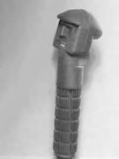
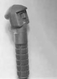
Advanced Hand Controls (AHC)(If Equipped)
AHC is only available on later model loaders. AHC operation is the same as mechanical hand controls above.
Two lights (Item 1) [B] on the left handle are always ON when the AHC is functioning correctly. If lights are blinking or do not come ON , see Advanced Hand Controls Troubleshooting Chart Page 82.
HYDRAULIC CONTROLS (Cont’d)
Auxiliary Hydraulics
Hydraulic fluid, tubes, fittings and quick couplers can get hot when running machine and attachments. Be careful when connecting and disconnecting quick couplers.
W–2220–1195
NOTE:(Advanced Hand Controls Only) These loaders have auxiliary proportional control for front auxiliary hydraulics only. Proportional control allows for slow–to–fast movement of auxiliary functions. EXAMPLE: If you move the auxiliary switch half way, the auxiliary function will move at approximately one–half speed.
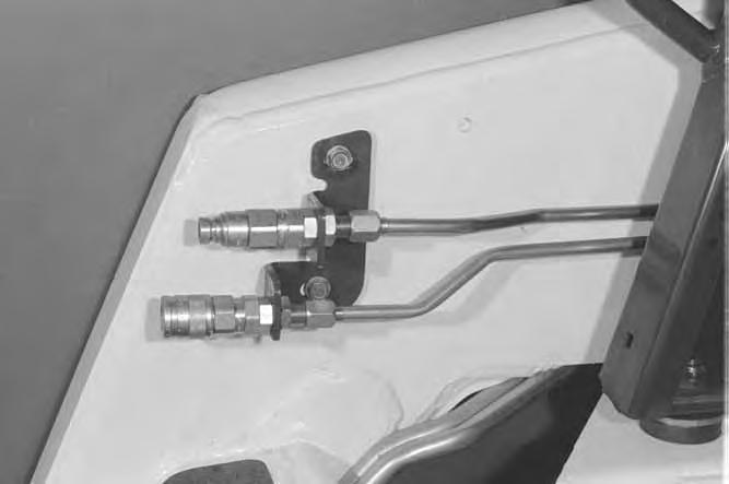
Quick Couplers (Flush Face)
To Connect: Remove any dirt or debris from the surface of both the male and female coupler halves, and from the outside diameter of the male coupler. Visually check the couplers for corroding, cracking, damage, or excessive wear, if any of these conditions exist, the coupler(s) must be replaced [A]
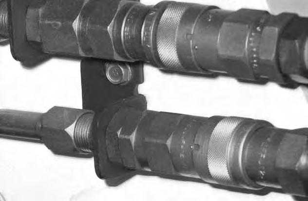
Install the male half coupler into the female half coupler. Full connection is made when the ball release sleeve slides forward on the female coupler and the sleeve is rotated so that the locking pins (Item 1) [B] and the groove (Item 2) [B] do NOT align (Locked Position). This will prevent accidental disconnection.
NOTE:If the locking pins and grooves (Item 3) [B] arealigned, accidental disconnection is possible.

To Disconnect: Rotate the ball release sleeve so that the grooves are aligned with the pins (Item 1) [B] in the female coupler.
Hold the male coupler. Retract the sleeve on the female coupler until the couplers disconnect.
Auxiliary hydraulics [C] are not standard, but can be a Factory Option or a Field Installed Accessory.
A loader without front or rear Auxiliary Hydraulics will not have switches in the control handles.
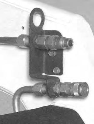
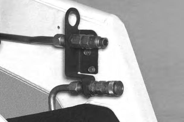
FRONT AUXILIARY QUICK COUPLERS
REAR AUXILIARY QUICK COUPLERS
HYDRAULIC CONTROLS (Cont’d)
Auxiliary Hydraulics (Cont’d)
Auxiliary Hydraulics Switch
• Momentary Operation
Press the Auxiliary Hydraulics Switch (Item 1) [A] once.
The light (Item 2) [A] will be ON.
• Continuous Operation
Press the Auxiliary Hydraulics Switch (Item 1) [A] a second time.
Both lights (Items 2 & 3) [A] will be ON.
• Disengage
Press the Auxiliary Hydraulics Switch (Item 1) [A] a third time.
Both lights (Items 2 & 3) [A] will be OFF.
NOTE:When the operator is seated and raises the seat bar, the Auxiliary Hydraulic System (Front and Rear) will deactivate. Press the Auxiliary Hydraulics Switch to reselect operating mode.

Front Auxiliary Hydraulics Operation (RIGHT Steering Lever)

• Set the Auxiliary Hydraulics Switch for Momentary Operation. (See above.)
• Push the switch (Item 1) [B] & [C] to the right or left to change the fluid flow direction to the front quick couplers. (EXAMPLE: Open and close grapple teeth.)
Front Auxiliary Hydraulics Continuous Operation (RIGHT Steering Lever)
• Set the Auxiliary Hydraulics Switch for Continuous Operation. (See above.)
• Push the front switch (Item 2) [B] or [C] to give the front quick couplers a constant flow of fluid. (EXAMPLE: Operate a backhoe.)
• To release from continuous flow operation, press the front switch (Item 2) [B] & [C] a second time.
NOTE:The secondary front auxiliary hydraulics and the rear auxiliary hydraulics operate from the same auxiliary section of the control valve. To operate only one of these auxiliary functions, disconnect the other.
Rear Auxiliary Hydraulics Operation (LEFT Steering Lever)
• Set the Auxiliary Hydraulics Switch for Momentary or Continuous Operation. (See above.)
• Push the switch (Item 3) [B] & [C] to the right or left to change the fluid flow direction to the rear quick couplers [D]. (EXAMPLE: Raise and lower rear stabilizers.) This switch also controls the available secondary front auxiliary. (Rear Auxiliary Hydraulics required)

HYDRAULIC CONTROLS (Cont’d)
Auxiliary Hydraulics (Cont’d)
Secondary Front Auxiliary Hydraulics
The secondary front auxiliary quick couplers are available as a Field Installed Accessory. These are used when there is a need for additional auxiliary hydraulics (EXAMPLE: Planer side shift).
• Connect the attachment to the secondary auxiliary hydraulics (Item 1) [A]
• Set the Auxiliary Hydraulics Switch for Momentary or Continuous Operation. (See Page 15.)
• Push switch (Item 1) [B] (left steering lever) to the right or left to change fluid flow direction. (EXAMPLE: Side shift on the Planer.)
NOTE:The secondary front auxiliary hydraulics and the rear auxiliary hydraulics operate from the same auxiliary section of the control valve. To operate only one of these auxiliary functions, disconnect the other.
HYDRAULIC CONTROLS (Cont’d)
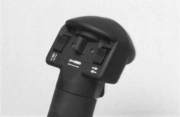
Attachment Functions Control
(Attachment Control Kit Required) (Item 1) [A]
When this kit is installed, you can use other switches on the right and left control handles (Deluxe Handles) for functions such as water spray, left/right turn signals (Europe only), raise/lower the left/right ends of the moldboard on a Grader, etc.
The following are examples only, consult Attachment Operation & Maintenance Manual:
Switch (Item 1) [B]
Switch (Item 2) [B]
Switch (Item 3) [B]
Left/Right Turn Signals
Left Moldboard Up/Down . . .
Right Moldboard Up/Down
Switch (Item 4) [B] Water Spray . . .
Diesel fuel or hydraulic fluid under pressure can penetrate skin or eyes, causing serious injury or death. Fluid leaks under pressure may not be visible. Use a piece of cardboard or wood to find leaks. Do not use your bare hand. Wear safety goggles. If fluid enters skin or eyes, get immediate medical attention from a physician familiar with this injury.
Relieving Hydraulic Pressure
Hydraulic pressure in the auxiliary hydraulic system can make it difficult to connect to the quick couplers.
Front And Rear Quick Couplers
With the engine running, turn the key switch quickly to the left (counterclockwise) past the OFF position. Hold key for at least five seconds after the engine comes to a complete stop. This relieves pressure that can be trapped in the auxiliary circuit which would make it difficult to engage quick couplers from an attachment.

Daily Inspection
Daily Inspection and Maintenance:
• Engine Oil Level
Maintenance work must be done at regular intervals. Failure to do so will result in excessive wear and early failures. The Service Schedule [A] is a guide for correct maintenance of the Bobcat loader. It is located inside the rear door of the loader and also in the MACHINE SIGN TRANSLATION Section Page 85. A
• Hydraulic/Hydrostatic Fluid Level
• Engine Air Filter, Air System for Damage or Leaks
• Engine Coolant Level, System for Damage or Leaks
• Operator Cab, Seat Belt, Seat Bar, Pedal or Hand Control Interlocks & Mounting Hardware
• Grease Pivot Pins (Lift Arms, Bob–Tach, Cylinders, Bob–Tach Wedges
• Tires for Wear or Damage and Correct Air Pressure
• Fuel Filter, Remove Trapped Water
• Loose or Broken Parts
• Safety Treads and Safety Signs (Decals)
• Bobcat Interlock Control System (BICS™)
• Lift Arm Support Device
NOTE:Fluids such as engine oil, hydraulic fluid, coolant, etc. must be disposed of in an environmentally safe manner. Some regulations require that certain spills and leaks on the ground must be cleaned in a specific manner. See local, state and federal regulations for correct disposal.
Instructions are necessary before operating or servicing machine. Read and understand the Operation & Maintenance Manual, Handbook and signs (decals) on machine. Follow warnings and instructions in the manuals when making repairs, adjustments or servicing. Check for correct function after adjustments, repairs or service. Untrained operators and failure to follow instructions can cause injury or death.
Getting Ready For Operation
Read the Operation & Maintenance Manual and the Operator’s Handbook (Item 1) [B] before operating the loader.
The Operation & Maintenance Manual and other manuals can be kept in a box (Item 2) [B] provided at the right hand side of the operator seat.

Operator must have instructions before running the machine. Untrained operators can cause injury or death.
Use the bucket or attachment steps, grab handles and safety treads (on top of the loader lift arms and frame) to get on and off the loader [C]
Safety treads are installed on the Bobcat loader to provide a slip resistant surface for getting on and off the loader. Keep safety treads clean and replace when damaged. See your Bobcat loader dealer for replacement treads.
GETTING READY FOR OPERATION (Cont’d)
Pull the seat lever (Item 1) [A].
Adjust the seat position for comfortable operation of the loader controls.
Fasten the seat belt snugly and adjust it so that the buckle is centered between your hips [B]
Avoid Injury Or Death
When operating the machine:
• Keep the seat belt fastened snugly.
• The seat bar must be lowered.
• Keep your feet on the pedal controls or footrests.
Failure to obey warnings can cause injury or death.
Lower the seat bar.
Be sure the parking brake is engaged.
Put all controls in the neutral position before you start the engine.
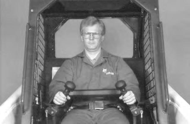
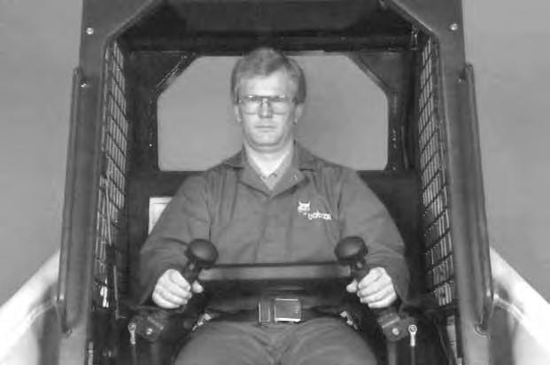
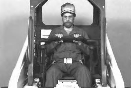
Foot Pedals: Keep your hands on the steering levers and feet on the foot pedals while seated in the loader [C]

Hand Controls: Keep your hands on the controls (Item 1) [D] and feet on the footrests (Item 2) [D]

Starting The Engine
WRONG
When an engine is running in an enclosed area, fresh air must be added to avoid concentration of exhaust fumes. If the engine is stationary, vent the exhaust outside. Exhaust fumes contain odorless, invisible gases which can kill without warning.
Avoid Injury Or Death
• Engines can have hot parts and hot exhaust gas. Keep flammable material away.
• Do not use machines in atmosphere containing explosive gas.
Normal Starting (Without BOSS®)
Adjust the seat position, fasten the seat belt and lower the seat bar. [C]
Engage the parking brake.

STARTING THE ENGINE (Cont’d)
Normal Starting (Without BOSS®) (Cont’d)
Put the foot pedals (or hand controls) and steering levers in NEUTRAL POSITION (center) (Item 1) [A]
Set the engine speed control to the 1/2 SPEED position (Item 2) [A]
Turn the key switch to the ON POSITION. The engine and transmission warning lights will be ON when the key switch is on and the engine is stopped (Item 3) [A].
Turn the key switch to START POSITION (Item 4) [A] and release it when the engine starts.
NOTE: Advanced Hand Controls Only: The hand controls must be in neutral before starting the engine. If the hand controls are not in neutral, the engine will start but lift and tilt hydraulic functions will not be able to be activated. Turn the key OFF and put hand controls in neutral position. Restart the engine.
Do not engage the starter for longer than 15 seconds at a time. Longer use can damage the starter by overheating. Cool the starter for one minute between uses.
When you release the key, it will return to the RUN POSITION (Item 5) [A].
STOP THE ENGINE IF THE WARNING LIGHTS DO NOT GO OFF.
NOTE:Upon failed start, if the key switch is turned OFF, wait for at least three seconds before turning the key switch ON to reset the fuel timer module.
Cold Temperature Starting (Without BOSS®) (See also Normal Starting)
Turn the key switch to the RUN POSITION.
Push the preheat switch (Item 1) [B] on the left side of the instrument panel.
The decal [C] on the left side of the operator cab shows the correct amount of time to hold the preheat switch.
Follow the steps under Normal Starting and repeat the preheat procedure until the engine starts.
If the temperature is below 32°F. (0°C.), perform the following to make starting the engine easier:
• Replace the engine oil with the correct type and viscosity for the anticipated starting temperature. (See ENGINE LUBRICATION SYSTEM Page 57 )
• Make sure the battery is fully charged.
• Install an engine heater, available from your Bobcat loader dealer.
STARTING THE ENGINE (Cont’d)
Normal Starting (With BOSS®)
Adjust the seat position, fasten the seat belt and lower the seat bar [A]
Put the foot pedals (or hand controls) and steering levers in NEUTRAL POSITION (center) (Item 1) [B]
Engage the parking brake.
Set the engine speed control to 1/2 SPEED position (Item2) [B].
Turn the key switch to the ON POSITION, one beep will sound and the display symbols will be ON [C]. Turn the key switch to the START POSITION. (See Cold Temperature Starting.) Release the key when the engine starts.
NOTE: Advanced Hand Controls Only: The hand controls must be in neutral before starting the engine. If the hand controls are not in neutral, the engine will start but lift and tilt hydraulic functions will not be able to be activated. Turn the key OFF and put hand controls in neutral position. Restart the engine.
Do not engage the starter for longer than 15 seconds at a time. Longer use can damage the starter by overheating. Cool the starter for one minute between uses.
When the key switch is turned ON, watch the alpha numeric display for SERVICE CODES. These codes are from the previous work shift when a WARNING may have occurred. (See SYSTEM ANALYSIS, SERVICE CODES Page 79 )
The codes may be viewed again by turning the key switch OFF and then ON again without starting the engine.
After the engine has been started, the BOSS controller will clear all codes from memory. The codes will not appear again unless the problem reoccurs. The alphanumeric display will again show the operating hours.
NOTE:Upon failed start, if the key is turned OFF, wait for at least three seconds before turning the key ON to reset the fuel timer module.
STARTING THE ENGINE (Cont’d)
Cold Temperature Starting (With BOSS®)
Do not use ether with glow plug (preheat) systems. Explosion can result which can cause injury or death.
See Normal Starting. Turn the key switch to the ON POSITION. The glow plug symbol (preheat) will be ON (Item 1) [A]
NOTE:If the display is showing SERVICE CODES, the timing of the glow plug activation may not be visible on the display. However, the glow plugs will be energized.
Characters on the display will be GLOXX where XX will indicate the remaining time the glow plugs will be energized.
Turn the key switch to the START POSITION and release when the engine starts. If the engine does not start, turn the key switch to the OFF POSITION and ON again. This will start the glow plug cycle again. When the engine is running, slowly move the engine speed control forward to increase engine RPM.
If the starting temperature is below 32°F. (0°C.), perform the following to make starting easier:
• Replace the engine oil with the correct type and viscosity for the anticipated starting temperature. (See ENGINE LUBRICATION SYSTEM Page 57.)
• Make sure the battery is fully charged.
• Install an engine heater. (See your Bobcat loader dealer.)
Warming The Hydraulic/Hydrostatic System
Let the engine run for a minimum of 5 minutes to warm the engine and hydrostatic transmission fluid before operating the loader. If the warning light comes ON when operating loader (cold), more warm up time is needed.
Stopping The Engine
Pull the engine speed control fully backward to decrease the engine speed. Turn the key switch to the OFF POSITION [B].
Off Position B
When the temperature is below –20°F. (–30°C.), hydrostatic oil must be warmed before starting. The hydrostatic system will not get enough oil at low temperatures and will be damaged. Park the machine in an area where the temperature will be above 0°F. (–18°C.) if possible.
Attachments And Buckets
Never use attachments or buckets which are not approved by Bobcat. Buckets and attachments for safe loads of specified densities are approved for each model. Unapproved attachments can cause injury or death.
The dealer can identify, for each model loader, the attachments and buckets approved by Bobcat Company. The buckets and attachments are approved for rated operating capacity and for secure fastening to the Bob–Tach.
The rated operating capacity for this loader is shown on a decal in the operator cab. (See SPECIFICATIONS Page 95 ) The rated operating capacity is determined by using a standard dirt bucket, and material of normal density, such as dirt or dry gravel. If longer buckets are used, the load center moves forward and reduces the rated operating capacity. If very dense material is loaded, the volume must be reduced.
Exceeding the rated operating capacity [A] can cause the following problems:
1.Steering the loader may be difficult.
2.Tires will wear faster.
3.There will be a loss of stability.
4.The life of the Bobcat loader will be reduced.
Use the correct size bucket for the type and density of material being handled. For safe handling of materials and avoiding machine damage, the attachment (or bucket) should handle a full load without going over the rated operating capacity for the loader. Partial loads make steering more difficult.
Maximum load to be carried when using a pallet fork are shown in figure [B]. See your Bobcat loader dealer for more information about pallet forks and other available attachments.
Do not exceed rated operating capacity. Excessive load can cause tipping or loss of control. W–2053–0887
ATTACHMENTS AND BUCKETS (Cont’d)
Installing The Bucket Or Attachment
The loader is equipped with the Bob–Tach system. The Bob–Tach is used for fast changing of buckets and attachments. See the Attachment Operation & Maintenance Manual to install other attachments.
Pull the Bob–Tach levers all the way up (Item 1) [A]
Enter the loader.
Fasten the seat belt, lower the seat bar and start the engine.
Release the parking brake.
Lower the lift arms and tilt the Bob–Tach forward.
Drive the loader forward until the top edge of the Bob–Tach is completely under the top flange of the bucket [A] (or other attachments).


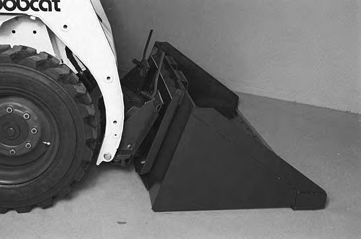
Be sure the Bob–Tach levers do not hit the bucket.
Tilt the Bob–Tach backward until the cutting edge of the bucket (or other attachment) is slightly off the ground [B]
Stop the engine and exit the loader.
Before you leave the operator’s seat:
• Lower the lift arms, put the attachment flat on the ground.
• Stop the engine.
• Engage the parking brake.
• Raise seat bar.
• (Foot Pedal Controls) Move pedals until both lock.
• (Mechanical Hand Controls) Move the hand controls until both lock.
The seat bar system must lock the lift and tilt controls in neutral when the seat bar is up. Service the system if hand controls do not lock correctly.
• (Advanced Hand Controls) Move the hand controls to the NEUTRAL POSITION to make sure that both lift and tilt functions are deactivated.
The seat bar system must deactivate the lift and tilt control functions when the seat bar is up. Service the system if hand controls do not deactivate.
W–2323–0698
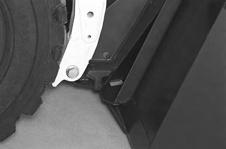
Push down on the Bob–Tach levers until they are fully engaged in the locked position [C]
The levers will contact the frame as shown (Item 1) [C] when locked.
If the levers do not engage in the locked position, see your Bobcat loader dealer for maintenance.
Bob–Tach levers have spring tension. Hold lever tightly and release slowly. Failure to obey warning can cause injury.
ATTACHMENTS AND BUCKETS (Cont’d)
The wedges (Item 1) [A] must extend through the holes (Item 1) [B] in the mounting frame of the bucket (or attachment), securely fastening the bucket to the Bob–Tach. The wedge is shown extending through the hole in the bucket [A]
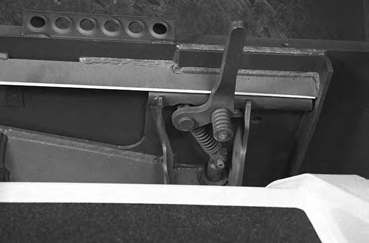
Bob–Tach wedges must extend through the holes in attachment. Levers must be fully down and locked. Failure to secure wedges can allow attachment to come off and cause injury or death.

Removing The Bucket Or Attachment
Put the attachment flat on the ground and lower or close the hydraulic equipment. If the attachment is hydraulically controlled (ie: combination bucket, backhoe, etc.), stop the engine and relieve hydraulic pressure in the auxiliary circuit (See Relieving Hydraulic Pressure, Page 17).
Raise the seat bar, unfasten the seat belt, set the parking brake and exit the loader.
Pull the Bob–Tach levers [C] all the way up.
Disconnect the hydraulic hoses, if necessary. Enter the loader.
Fasten the seat belt, lower the seat bar and start the engine
Release the parking brake.
Lower the lift arms and tilt the Bob–Tach forward.
Move the loader backward, away from the bucket or attachment [D]
Operating Procedure
When operating on a public road or highway, always follow local regulations. For example: Slow Moving Vehicle sign or direction signals may be required. Always warm the engine and hydrostatic system before operating the loader.
Machines warmed up with moderate engine speed and light load have longer life.
B
Operate the loader with the engine at full speed for maximum horsepower. Move the steering levers only a small amount to operate the loader slowly.
New operators must operate the loader in an open area without bystanders. Operate the controls until the loader can be handled at an efficient and safe rate for all conditions of the work area.
With a full bucket, go up or down the slope with the heavy end toward the top of the slope [A] & [B]
With empty bucket, go down or up the slope with the heavy end toward the top of the slope [C] & [D].
C
• Keep the lift arms as low as possible.
• Do not travel or turn with the lift arms up.
• Turn on level ground.
• Go up and down slopes, not across them.
• Keep the heavy end of the machine uphill.
• Do not overload the machine.
Failure to obey warnings can cause the machine to tip or roll over and cause injury or death.
Raise the bucket only high enough to avoid obstructions on rough ground.
D
OPERATING PROCEDURES (FOOT PEDALS)
Filling The Bucket
Push down on the top of the lift pedal until the lift arms are all the way down.
Push the top of the tilt pedal to put the cutting edge of the bucket on the ground [A]
Drive slowly forward into the material.
Push the bottom of the tilt pedal to raise the front of the bucket [B].
Drive backward away from the material.
Load, unload and turn on flat level ground. Do not exceed rated operating capacity shown on sign (decal) in cab. Failure to obey warnings can cause the machine to tip or roll over and cause injury or death.
W–2056–1187
Emptying The Bucket
Push down on the bottom of the lift pedal to raise the bucket over the truck box or bin [C].
Drive forward slowly until the bucket is over the top of the truck box or bin.
Push the top of the tilt pedal until the bucket is empty [C]. If all the material is near the side of the truck or bin, push it to the other side with the bucket.
Never dump over an obstruction, such as a post, that can enter the operator cab. The machine could tip forward and cause injury or death.
W–2057–0694
OPERATING PROCEDURES (FOOT PEDALS) (Cont’d)
Digging Into The Ground
Put the lift arms all the way down.
Push the top of the tilt pedal until the cutting edge of the bucket is on the ground.
Drive forward slowly and continue to tilt the bucket down until it enters the ground [A]
Push the bottom of the tilt pedal a small amount to increase traction and keep an even digging depth. Continue to drive forward until the bucket is full.
When the ground is hard, raise and lower the cutting edge of the bucket with the tilt pedal while driving forward slowly.
Push the bottom of the tilt pedal to tilt the bucket backward as far as it will go when the bucket is full [B]
Leveling The Ground (Using Lift Arms In Float Position)
Push the top (toe) of the lift pedal all the way forward until the pedal is in the locked position to put the lift arms in a float position [C]
Push the tilt pedal to change the position of the cutting edge on the bucket.
With the bucket tilted farther forward, there is more force on the cutting edge and more loose material can be moved.
Never drive forward when the hydraulic control for lift arms is in float position.
I–2005–1285
Drive backward to level loose material.
Push the bottom of the lift pedal to unlock from the continuous flow position.