23 minute read
SAFETY INSTRUCTIONS


SAFETY IS THE OPERATOR’S RESPONSIBILITY
The Skid Steer Loader is a highly maneuverable and compact machine. In operation, it is rugged and useful under a wide variety of conditions. This presents an operator with hazards associated with off highway, rough terrain applications. The loader has an internal combustion engine with resultant heat and exhaust. All exhaust gases can kill or cause illness so the loader must be used with adequate ventilation. The loader has a spark arrestor muffler which is required for operation in certain areas.
The dealer explains the capabilities and restrictions of the loader and attachments for each application. The dealer demonstrates the safe operation of the loader according to Melroe’s instructional materials; which are also available to operators. The dealer can also identify unsafe modifications or use of unapproved attachments. The attachments and buckets are designed for rated capacity and secure fastening to the loader. The user must check with the dealer, or Melroe Company literature, to determine safe loads of materials of specified densities for his loader–attachment combination.
The following publications provide information on the safe use and maintenance of the loader and attachments:
• The Delivery Report is used to assure that complete instructions have been given to the new owner and that the machine is in safe operating condition.
• The Operation and Maintenance Manual delivered with the loader gives operating information as well as routine maintenance and service procedures. It is a part of the loader and can be stored in a container (later models) provided inside the cab. Replacement Operation and Maintenance Manuals can be ordered from your Bobcat loader dealer.
• The loader has machine signs (decals) which instruct on the safe operation and care. The signs andtheir locations are shown in the Operation and Maintenance Manual. Replacement signs are available from your Bobcat loader dealer.
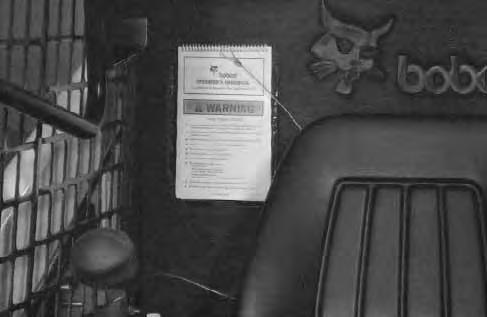
• The loader has a plastic Operator’s Handbook fastened to the operator cab. Its brief instructions are convenient to the operator. The Handbook is available from your dealer in an English edition or one of many other languages. See your Bobcat dealer for more information on translated versions.
• The EMI Safety Manual (available in Spanish) delivered with the loader gives general safety information.
• The Service Manual and Parts Manual are available from your dealer for use by mechanics to do shop–type service and repair work.
• The Skid–Steer Loader Operator Training Course is available through your local Bobcat dealer. This course provides information for safe and efficient operation of the Bobcat loader. The course is available in English and Spanish versions.
• The Bobcat Skid–Steer Loader Safety Video is available from your Bobcat Dealer.
The dealer and owner/operator review the recommended uses of the loader and attachments when the loader is delivered. If the owner/operator will be using the loader for a different application(s) he must ask the dealer for recommendations on the new use.
1–888–258–0808
When you call, you will be directed to a locationin your state/city for information about burried lines (telephone, cable TV, water, sewer, gas,etc.).
Before Operating The Bobcat Loader
Safety Alert Symbol
This symbol with a warning statement means: “Warning, be alert! Your safety is involved!” Carefully read the message that follows.
The Bobcat loader and attachment must be in good operating condition before use.
Check all of the items on the Bobcat Service Schedule Decal under the 8–10 hour column or as shown in this Manual.
SAFE OPERATION NEEDS A QUALIFIED OPERATOR *
A QUALIFIED OPERATOR MUST DO THE FOLLOWING:
• UNDERSTAND THE WRITTEN INSTRUCTIONS, RULES AND REGULATIONS
• The written instructions from Bobcat Company include the Delivery Report, Operation & Maintenance Manual, Operator’s Handbook, Safety Manual and machine signs (decals).
• Check the rules and regulations at your location. The rules may include an employer’s work safety requirements. Regulations may apply to local driving requirements or use of a Slow MovingVehicle (SMV) emblem. Regulations may identify a hazard such as a utility line.
• HAVE TRAINING WITH ACTUAL OPERATION
Operator must have instructions before running the machine. Untrained operators can cause injury or death.
W–2001–1285
Warnings on the machine and in the manuals are for your safety. Failure to obey warnings can cause injury or death.
W–2044–1285
• Operator training must consist of a demonstration and verbal instruction. This training is given by your Bobcat dealer before the product is delivered.
• The new operator must start in an area without bystanders anduse all the controls until he can operate the machine and attachment safely under all conditions of the work area. Always fasten seat belt before operating.
• Operator Training Courses are available from your Bobcat dealer in English and Spanish. They provide information for safe and efficient equipment operation. Safety videos are also available.
• Service Safety Training Courses are available from your Bobcat dealer. They provide information for safe and correct service procedures.
• KNOW THE WORK CONDITIONS
• Know the weight of the materials being handled. Avoid exceeding the Rated Operating Capacity of the machine. Material which is very dense will be heavier than the same volume of less dense material. Reduce the size of load if handling dense material.
• The operator must know any prohibited uses or work areas, for example, he needs to know about excessive slopes.
• Know the location of any underground lines. Call local utilities or the TOLL FREE phone number found in the SAFETY INSTRUCTIONS Section of this manual.
• Wear tight fitting clothing. Always wear safety glasses when doing maintenance or service. Safety glasses, hearing protection or special applications kit are required for some work.See your dealer about Bobcat Safety equipment. * For an operator be qualified, he must not use drugs or alcoholic drinks which impair his alertness or coordination while working. An operator who is taking prescription drugs must get medical advice to determine if he can safely operate a machine. SI02–0400
Fire Prevention
The loader has several components that are at high temperature under normal operating conditions. The primary source of high temperatures is the engine and exhaust system. The electrical system, if damaged or incorrectly maintained, can be a source of arcs or sparks.
Flammable debris (leaves, straw, etc.) must be removed regularly. If flammable debris is allowed to accumulate, it will increase the fire hazard. The loader must be cleaned as often as necessary to avoid this accumulation. Flammable debris in the engine compartment is a fire hazard when the loader is parked with a hot engine.
The spark arrestor muffler is designed to control the emission of hot particles from the engine and exhaust system, but the muffler and the exhaust gases are still hot.
• Do not use the Bobcat loader where exhaust, arcs, sparks or hot components can contact flammable material, explosive dust or gases.
• The engine compartment and engine cooling system must be inspected everyday and cleaned if necessary to prevent fire hazard and overheating.
• Check all electrical wiring and connections for damage. Keep the battery terminals clean and tight. Repair or replace any damaged part.
• Check fuel and hydraulic tubes, hoses and fittings for damage and leakage. Never useopen flame or bare skin to check for leaks. Tighten or replace any parts that show leakage. Always clean fluid spills. Do not use gasoline or diesel fuel for cleaning parts. Use commercial nonflammable solvents.
• Do not use ether or starting fluids on this engine. It has glow plugs. These startingaids can cause explosion and injure you or bystanders.
• Always clean the loader and disconnect the battery before doing any welding. Cover rubber hoses, battery and all other flammable parts. Keep a fire extinguisher near the loader when welding. Have good ventilation when grinding or welding painted parts. Wear dust mask when grinding painted parts. Toxic dust or gas can be produced.
• Stop the engine and let it cool before adding fuel. No smoking!
• Use the procedure in the Operation & Maintenance Manual for connecting the battery.
• Use the procedure in the Operation & Maintenance Manual for cleaning the spark arrestor muffler.
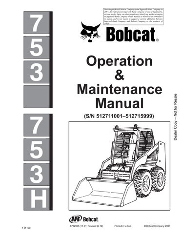
• Know where fire extinguishers and first aid kits are located and how to use them.
A fire extinguisher is available from your Bobcat dealer. The fire extinguisher can be installed in the location shown [A] SI03–0398
MACHINE SIGNS (DECALS)
Follow the instructions on all the Machine Signs (Decals) that are on the loader. Replace any damaged machine signs and be sure they are in the correct locations. Machine signs are available from your Bobcat loader dealer.
MACHINE SIGNS (DECALS) (Cont’d)

INSTRUMENT PANEL (Standard)
The instrument panel has the following instruments [A]:
1. LIGHT SWITCH (OPT.) – Controls the work and travel lights.
2. KEY SWITCH – For starting, stopping and preheating the engine.
3. FUSE (ACCESSORIES) – To protect the electrical system from overload.
4. FUSE (IGNITION) – To protect the electrical system from overload.
5. HOURMETER – Records the total operating hours of the loader.
6. FUEL GAUGE – Shows the amount of fuel in the fuel tank.
7. ENGINE TEMPERATURE GAUGE – Shows the engine coolant temperature.
8. ENGINE WARNING LIGHT – Engine oil pressure is low. Stop the engine if the light comes ON.
9. TRANSMISSION WARNING LIGHT – Low transmission charge pressure, hydraulic filter needs replacement or high fluid temperature. Stop the engine if the light comes ON.
10. VOLTMETER – Shows the condition of the battery and the rate of charge.
11. PREHEAT switch – For preheating the glow plugs before starting the engine.
12. AUXILIARY HYDRAULICS MODE SWITCH (Opt.) – For engaging the auxiliary hydraulics (front & rear).
INSTRUMENT PANEL (Optional)
The following items are located on the instrument panel [A] & [B]:
1. KEY SWITCH – Controls the starting and stopping of the engine. If engine doesn’t start turn the key to the OFF position for 3 seconds to reset the fuel timer module.
2. LIGHT SWITCH (OPTIONAL) – Controls the work and travel lights.
3. DIAGNOSTIC COUPLER – Connector for diagnostic tool to make service checks of the system operation unit and other components.
4. DISPLAY PANEL – The display has the following symbols and functions (Ref. 6 thru 19).
5. OPTIONAL HYDRAULICS MODE SWITCH – For engaging the auxiliary hydraulics (front and rear).
6. FUEL – Shows the amount of fuel in the tank.
7. BATTERY VOLTAGE – Shows the condition of the battery and charge rate. Also will indicate a WARNING for high and low voltage.
8. ENGINE OIL SYMBOL – Shows engine oil pressure. Flashing symbol indicated low oil pressure.
9. ENGINE COOLANT SYMBOL – Shows engine coolant temperature and/or low coolant level (SHUTDOWN).
10. FUEL FILTER – If fuel pump and bar flashes it is a low fuel WARNING H2O symbol indicates water in the fuel filter (NOT FUNCTIONAL AT THIS TIME).
11. SHUTDOWN SYMBOL – The symbol is associated with any shutdowncondition. When this symbol comes ON the shutdown will occur in 30 seconds. During shutdown the buzzer will sound continuously and the symbol will flash until the key is turned OFF.
NOTE:The engine can be restarted for 30–second periods to move the loader after a shutdown condition.
12. WARNING SYMBOL – The symbol will be ON when any warning or shutdown is activated. The warning symbol is also used to indicate a warning if there is no related symbol on the display. During a warning the buzzer will beep three times and symbol will be on continuously.
13. HOURMETER –Records the total operating hours of the loader. The five character code will display the operating hours to the nearest tenth. When SHUTDOWNS or WARNINGS occur an alpha–numeric code will be displayed in the hourmeter area to inform the operator of the problem. (See Page 62 for code listing.) During a SHUTDOWN or WARNING the hourmeter symbol is not visible.
14. CHARGE PRESSURE AND FILTER CONDITION – Flashing symbol indicates low fluid charge pressure and SHUTDOWN. If arrows are ON with gear/drop it is fluid charge pressure. This symbol will also indicate a clogged hydraulic fluid filter.
15. AIR FILTER CONDITION – This symbol will indicate a clogged air filter element.
16. GLOW PLUG – The symbol will flashwhen the glow plugs are energized. The hourmeter will also contain characters GLOXX where XX indicates the remaining time the glow plugs will beON. Glow plug will count down in 5 second increments.
17. ENGINE SPEED – This symbol will indicate an engine overspeed WARNING and SHUTDOWN.
18. PARKING BRAKE – This symbol will indicate when the brake is engaged (NOT FUNCTIONAL AT THIS TIME.
19. HYDRAULIC FLUID TEMPERATURE – This symbol will indicate a high fluid temperature and SHUTDOWN or WARNING.
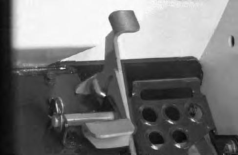
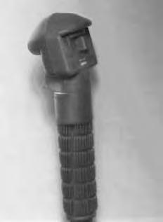
Engine Speed Control
The engine speed control (Item 1) [A] is at the right side of the operator’s seat. Engine speed is controlled by moving the control forward to increase the enginespeed and backward to decrease the engine speed.
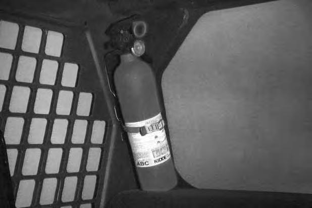
Parking Brake
Engage the parking brake by pushing down on the top of the pedal
Avoid Injury Or Death
When operating the machine:
• Keep the seat belt fastened snugly.
• The seat bar must be lowered.
• Keep your feet on the pedal controls.
W–2046–0595
The steering lever (Item 1) [A] are on the right and left side in front of the seat.
For safe control of the loader always move the levers slowly and smoothly. Only a small movement is necessary to move the loader.
The steering levers control forward and reverse travel of the loader [B]
FORWARD TRAVEL – Push both levers forward.
REVERSE TRAVEL – Pull both levers backward.
NORMAL TURNING – Move one lever farther forward than the other.
FAST TURNING – Push one lever forward and pull the other lever backward.
For slow travel speed, push the steering levers forward only a small amount.
To increase travel speed, push both levers farther forward.
For maximum pushing force, push the levers forward only a small amount with the engine at full RPM.
Backward
RIGHT TURN Operation & Maintenance Manual –6–753, 753H Bobcat Loader
Left Turn
Hydraulic Controls
Foot Pedals
Keep both feet on pedals while operating machine. Failure to do so can cause serious injury.
Put your feet on the pedals and KEEP THEM THERE any time you operate the loader.
Two foot pedals (Item 1) [A] control the hydraulic cylinders for the lift and tilt function.
Lift Arm Operation
The left pedal controls the lift arms. Push on the bottom (heel) (Item 2) [A] of the pedal to raise the lift arms.
Push on the top (toe) (Item 3)[A] of the pedal to lower the lift arms.
Push the top (toe) (Item 3) [A] of the lift pedal all the way forward until it locks into detent (float). Use the float position of the lift arms to level loose material while driving backward.
Tilt Operation (Bucket)
The right pedal controls the action of the bucket. Push the top (toe) (Item 4)[A] of the pedal to tiltthe bucket forward.
Push the bottom of the pedal (heel) (Item 5)[A] to tilt the bucket backward.
Bucket Position Valve Operation (Optional)
The function of the bucket positioning valve isto keep the bucket in the same approximate position it is placed in, prior to the upward lift cycle.
Bucket positioning functions automatically during the upward lift cycle only.
HYDRAULIC CONTROLS (Cont’d)
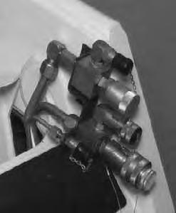
Auxiliary Hydraulics Operation (Optional)
AVOID BURNS
Hydraulic fluid, tubes, fittings and quick couplers can get hot when running machine and attachments. Be careful when connecting and disconnecting quick couplers.
W–2220–0396
NOTE:Both steering lever controls are blank (no switches) as standard.
Press the mode switch (Item 1) [A] (on the instrument panel) to allow for the front and optional rear auxiliary hydraulics, the light (Item 2) [A] will come ON
The switch (Item 1) [B] on the right steering lever controls the front auxiliary hydraulics and the switch (Item 2) [B] on the left steering lever controls the rear auxiliary hydraulics.

Switch (Item 4) [B] controls the optional horn.

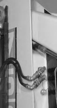
FRONT AUXILIARY CONTROL (OPTIONAL):
Push switch (Item 1) [B] in the right or left direction (with mode switch engaged & top lightON) to change fluid flow direction to the front quick couplers [C] (Example: Raise or lower rear stabilizers).
REAR AUXILIARY CONTROL (OPTIONAL)
Push the switch (Item 2) [B] in the right or left direction (with mode switch engaged & top lightON ) to change the fluid flow direction to the rear quick couplers [C] (Example: Raise or Lower rear stabilizers).
DETENT CONTROL:
Push the mode switch (Item 1) [A] the second time to engage the detent function and both lights (Items 2 & 3) [A] will come ON . Push the front button to give the front auxiliary hydraulics a constant flow of fluid[B]. (Example: Operate a backhoe).
To release the detent position, push the switch (Item 3) [B] again.
RELIEVE PRESSURE AT FRONT QUICK COUPLERS:
Turn the key switch to the aux. pressure relief position (all the way to the left and hold the key in this position untilthe engine stops) to release the hydraulic pressure at the front quick couplers.
RELIEVE PRESSURE AT REAR QUICK COUPLERS
With the engine running, press the mode switch (Item 1) [A] to engage the auxiliary hydraulics, the light (Item 2) [A] will come ON .
Push the heel of the tilt pedal so the hydraulic fluid goes over the main relief pressure and at the same time push switch (Item 2) [B] back and forth several times torelieve the pressure at the rear quick couplers. Release the tilt pedal. Stop the engine.
HYDRAULIC CONTROLS (Cont’d)
Auxiliary Hydraulics Operation (Optional)
NOTE:The right and left steering lever control are bland (no switches) as standard.
Press the mode switch (Item 1) [A] (on the instrument panel) to allow for the front and rear auxiliary hydraulics, the light (Item 2) [A] will come ON.
The switch (Item 1)[B] on the rightsteering lever controls the front auxiliary hydraulics and the switch (Item 2) [B] on the left steering lever control the rear auxiliary hydraulics.
Switch (Item 4) [B] controls the optional horn.
FRONT AUXILIARY CONTROL:
Push switch (Item 1) [B] in the right or left direction (with mode switch engaged & top light ON to change fluidflow direction to the front quick couplers[C]. (Example: Open and close grapple teeth.)
OPTIONAL REAR AUXILIARY CONTROL:
Push the switch (Item 2) [B] in the right or left direction (with mode switch engaged & top light ON to change the fluid flow direction to the rear quick couplers [C] (Example: Raise or lower rear stabilizers.)
DETENT CONTROL:
Push the mode switch (Item 1) [A] the second time to engage the detent function and both lights (Items 2 & 3) [A] will come ON. Push the front button (Item 3) [B] to give the front auxiliary hydraulics a constant flow of fluid. (Example: Operate a backhoe.)
To release the detent position, push the switch (Item 3) [B] again.

RELIEVE PRESSURE AT FRONT QUICK COUPLERS:
Turn the key switch to the OFF position, as the engine stops running, turn the key switch all the way to the left (hold the key in this position until the engine stops) to release the hydraulic pressure at the front quick couplers.
RELIEVE PRESSURE AT REAR QUICK COUPLERS:
With the engine running, press the mode switch (Item 1) [A] to engage the auxiliary hydraulics, the light (Item 2) [A] will come ON.
Push the heel of the tilt pedal so the hydraulic fluid goes over the main relief pressure and at the same time push switch (Item 2) [B] back and forth several times to relieve the pressure at the rear quick couplers. Release the tilt pedals. Stop the engine.

FRONT AUXILIARY QUICK COUPLERS REAR AUXILIARY QUICK COUPLERS (OPTIONAL) (OPTIONAL)

HYDRAULIC CONTROLS (Cont’d)
Auxiliary Hydraulics Operation – 753H (Optional)
Press the mode switch (Item 1) [A] (on the instrument panel) once to engage the auxiliary hydraulics, for momentary operation. The light (Item 2) [A] will come ON. Press the mode switch a secondtime for continuous operation. Both lights (Items 2 & 3) [A] will come ON. Pressing the mode switch a third time will disengage the auxiliary hydraulics and both lights will be OFF.
The switches (Item1 through Item 5) [B] on the right and left steering levers control the front and rear auxiliary hydraulics.

Switch (Item 6) [B] controls the optional water kit. Switch (Item 7) [B] controls the optional horn. Switch (Item 8) [B] controls the optional left/right turn signals.
FRONT AUXILIARY CONTROL (OPTIONAL)
(Momentary) (Normal Flow):
Push switch (Item 1) [B] in the right or left direction(with mode switch engaged) for momentary or continuous operation to change fluid flow direction to the front quick couplers (Item 1) [C]. (Example: Open and close grapple teeth.)

FRONT AUXILIARY CONTROL (OPTIONAL)
(Continuous) (Detent) (Normal Flow):
Push the front switch (Item 2)[B] once (with mode switch engaged for continuous operation) for continuous flow to the front auxiliary quick couplers (Item 1) [C]. (Example: backhoe.) To disengage continuous (detent) flow, push switch (Item 2) [B] a second time.
If the high horsepower switch is in the ON position, High Horsepower Hydraulics will flow through the front auxiliary quick coupler. Damage to unapproved attachments can result. Leave the switch OFF for backhoe operation.
SECONDARY AUXILIARY (Momentary Only):
There is also a set of couplers (Item 2) [C] on the right front of the loader. These couplers are used when there is an additional connection needed for attachment operation

Push switch (Item 3) [B] in the right or left direction (with mode switch engaged) for momentary operation, to change the fluid flow direction to the secondary auxiliary couplers (Item 2) [C]. (Example: Side shift on the Planer.)
Push the top or bottom of either switch (Items 4 or 5) [B] (with mode switch engaged for momentary or continuous operation) to change fluid flow to the attachments [C]
NOTE:When the loader is equipped with the second and rear auxiliaries, disconnect the rear auxiliary couplers so both auxiliaries do not function at the same time.
FRONT AUXILIARY QUICK COUPLERS (OPTIONAL)
SECONDARY AUXILIARY QUICK COUPLERS (OPTIONAL)
HYDRAULIC CONTROLS (Cont’d)
REAR AUXILIARY CONTROL (OPTIONAL)
Engage the mode switch for momentary operation (one light). Push switch (Item 3) [B], Page 7, right or left to change the fluid flow direction to the rear quick couplers (Item 1) [A]. (Example: Raise and lower the rear stabilizers).
NOTE:When the loader is equipped with rear and second auxiliaries, disconnect the second auxiliary couplers so both auxiliaries do not function at the same time.
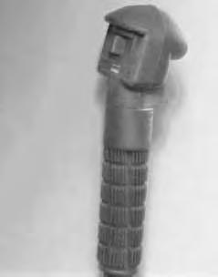
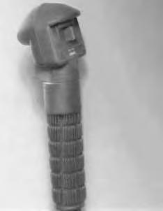
RELIEVE PRESSURE AT REAR COUPLERS (OPTIONAL)
With the engine OFF, use a rag to cover the quick couplers and tap the poppet with a wooden dowel. This will release trapped pressure in the hydraulic circuit.

RELIEVE PRESSURE AT FRONT COUPLERS (OPTIONAL)
With the engine running, turn ignition switch quickly to the left (counterclockwise) past the OFF position and hold until engine comes to a complete stop. This relieves pressure that may be trapped in the front auxiliary circuit which would hinder the engagement of attachment couplers.
AUXILIARY HIGH HORSEPOWER HYDRAULIC OPERATION:
The ON/OFF toggle switch (Item 1)[B] located on the left side of the operator’s seat controls the High Horsepower function

The High Horsepower function provides additional GPM to the system to operate a High Horsepower attachment (Example: Planer). There is a total of 24 GPM available to operate the attachment. System pressure is also increased from 2300–3300 PSI while the High Horsepower function is in use.
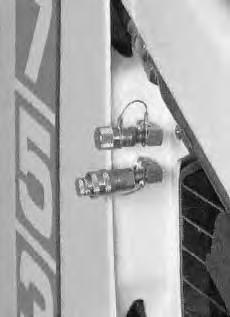
NOTE:Use only the large quick couplers for the High Horsepower function.
With the toggle switch in the OFF position, connect the attachment quick couplers to the large quick couplers (Item 1) [C] on the left front of the loader. The High Horsepower attachment may have a case drain which needs to be connected to the screw on male coupler (Item 2) [C] on the left front of the loader.

When all the couplers are connected turn the toggle switch to the ON position. For continuous high pressure/high flow in forward direction push the Detent switch (Item 2) [B], Page 7, on the front side of the right steering lever (the mode switch must bein the continuous flow mode. (See Page 7.) To stop continuous flow push the Detent switch a second time.
Momentary operation of the front auxiliary is also possible with the toggle switch in the ON position (the mode switch must be either in the Momentary or in the Continuous mode). Momentary forward flow (high flow and high pressure) results from pushing the switch (Item 1), Page 7, to the right steering lever. (Example: closing a LaBounty Shear.) Momentary reverse flow (highpressure and low flow) results from pushing the switch (Item 1), Page 7, to the left. (Example: opening a LaBounty Shear.)
Daily Inspection
The loader must be in good operating condition [A]
Check the following items:
• Engine Oil
• Hydraulic/Hydrostatic Fluid
• Engine Cooling System
• Operator Cab, Seat Belt, Seat Bar & Pedal Interlocks
• Lift Arm & Cylinder Pivot Pins
• Tires & Tire Pressure
• Any Loose or Broken Parts
• Safety Tread & Safety Signs
• Check the instrument panel display readout for faulty codes. (See Page 63.)
Follow the maintenance requirements on the Service Schedule Decal, located inside the rear door [B].
Instructions are necessary before operating or servicing machine. Read and understand the Operation & Maintenance Manuals, Handbook and signs (decals) on machine. Follow warnings and instructions in the manuals when making repairs, adjustments or servicing. Check for correct function after adjustments, repairs or service. Untrained operators and failure to follow instructions can cause injury or death.
W–2003–0199
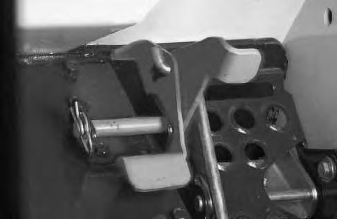
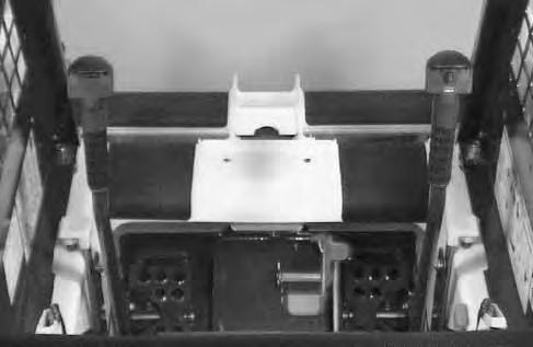
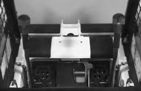
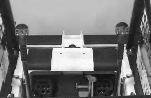
Seat Bar Restraint System
The seat bar restraint system has a pivoting seat bar (Item 1) [A] with arm rests and has spring loaded interlocks for the lift and tilt control pedals. The operator controls the use of the seat bar. The seat bar in the down position helps to keep the operator in the seat. The interlocks require the operator to lower the seat bar in order to operate the foot pedal controls. When the seat bar is up, the lift and tilt control pedals are locked when returned to the neutral position .
AVOID INJURY OR DEATH
When operating the machine:
• Keep the seat belt fastened snugly.
• The seat bar must be lowered.
• Keep your feet on the pedal controls.
W–2046–0595
The spring loaded interlocks (Item 1) [B] control the locking and unlocking functions of the control pedals.
The interlocks (Item 1) [B] require the operator to lower the seat bar (Item 2) [B] which allows the operator to move the foot pedals to control the lift and tilt functions
When the seat bar is lowered, it pushes the interlock (Item 1) [B] down on both sides, releasing the pedal linkages (Item 3) [B] from the interlocks .
The pedals will pivot in both directions when the interlock is down.
AVOID INJURY OR DEATH
Before you leave the operator’s seat:
• Lower the lift arms, put the attachment flat on the ground.
• Stop the engine.
• Engage the parking brake.
• Raise seat bar, move pedals until both locked.
W–2045–1086
The seat bar system must lock the lift and tilt control pedals in neutral when the seat bar is up. Service the system if pedals do not lock correctly.
W–2105–1285
When the seat bar is raised, spring forces raise the interlocks [C].
The foot pedals will not pivot when the interlock is up. Refer to the PREVENTIVE MAINTENANCE Section for Seat Bar Restraint System Inspection & Maintenance (See Page 36.)

Getting Ready For Operation
Read the Operation & Maintenance Manual and the Operator’s Handbook before operating the loader [A]
Operator must have instructions before running the machine. Untrained operators can cause injury or death.
W–2001–0596
Use the bucket or attachment steps, grab handles and safety treads (on top of the loader lift arms and frame) to get on and off the loader [B]
Safety treads are installed on the Bobcatloader to provide a slip resistant surface for getting on and off the loader. Keep safety treads clean and replace when damaged. Replacement treads are available from your dealer.
Pull the seat lever (Item 1)[C] and adjust the seat position for comfortable operation of the loader controls.


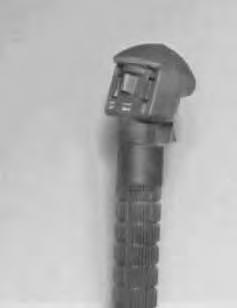
Fasten the seat belt snugly and adjust it so that the buckle is centered between the hips [D].
AVOID INJURY OR DEATH
When operating the machine:
• Keep the seat belt fastened snugly.
• The seat bar must be lowered.
• Keep your feet on the pedal controls.
W–2046–0595
GETTING READY FOR OPERATION (Cont’d)
Lower the seat bar [A]
Be sure the parking brake is engaged.
All controls must be in the neutral position before you start the engine. (See Starting the Engine, Page 17.)
Keep feet on the pedals while seated in the loader [B].


When an engine is running in an enclosed area, fresh air must be added to avoid concentration of exhaust fumes. If the engine is stationary, vent the exhaust outside. Exhaust fumes contain odorless, invisible gases which can kill without warning.
W–2050–1285
AVOID INJURY OR DEATH
• Engines can have hot parts and hot exhaust gas. Keep flammable material away.
• Do not use machines in atmosphere containing explosive gas.
W–2051–1086
Starting The Engine
Normal Starting Condition (Standard)
Adjust the seat position for comfortable operation of the foot pedals and steering levers.
Fasten the seat belt snugly and adjust it so the buckle is centered between the hips.
Lower the seat bar [A]
Put the foot pedals and steering levers in neutral (center) position (Item 1) [B]
Set the engine speed control to the half speed position (Item 2) [B]
Turn the key to the ON position. The engine and transmission warning lights will beON when the key is on and the engine is stopped (Item 3) [B].
Turn the key to start position (Item 4) [B] and release it when the engine starts.
Do not engage the starter for longer than 15 seconds at a time. Longer use can damage the starter by overheating. Cool the starter for one minute between uses.
When the engine starts, release the key and it will return to the run position (Item 5) [B]
STOP THE ENGINE IF THE WARNING LIGHTS DO NOT GO OFF.
Without turning the key to the START position, turn the key to the RUN position (Item 5) [B] for starting theloader in cold weather (See Cold Temperature Starting Condition Page 18.)
NOTE:Upon failed start, if the Key Switch is turned OFF, wait for at least three seconds before turning the Key Switch ON to reset the fuel timer module.
Do not use ether with glow plug (preheat) systems. Explosion can result which can cause injury or death.
W–2071–1285
Cold Temperature Starting Condition – (Standard)
See Normal Starting Condition, Page 17. Turn the key switch to the RUN position.
Push the PREHEAT switch (Item 1) [A] on the left side of the instrument panel to preheat the glow plugs.
Refer to the decal on the left side of the operator cab for operation of the preheat system [B]
Follow the steps under Normal Starting Condition and repeat the Preheating procedure until the engine starts.
If the temperature is below 32°F (0°C), use the following procedure to make starting the engine easier:
Replace the engine oil with the correct type and viscosity for the anticipated starting temperature. (See Oil Specifications, Page 42.)
Make sure the battery is at full charge.
Install a block or tank heater on the engine.
Warning The Hydraulic/Hydrostatic System
Avoid Injury Or Death
• Before lifting, check fasteners on single point lift and operator cab.
• Assemble front cab fasteners as shown in this manual.
• Never allow riders in the cab or bystanders within 15 feet (5 meters) while lifting the machine.
W–2007–0497
Let the engine run for a minimum of 5 minutes to warm the engine and hydrostatic transmission fluid before operating the loader. If the warning light comes ON when operating the loader (cold), more warm up time is needed.
STARTING THE ENGINE (Cont’d)
Normal Starting Condition (Optional)
Adjust the seat position for comfortable operation of the foot pedals and steering levers.
Fasten the seat belt snugly and adjust it so the buckle is centered between the hips.
Lower the seat bar [A]
Put the foot pedals and steering levers in neutral(center) position (Item 1) [B]
Be sure the parking brake is engaged.
Set the engine speed control to the 1/2 speed position (Item 2) [B]
Turn the key to ON position, one beep will sound and the display symbols will be ON [C]. Turn the key to START (Also See Cold Temperature Starting Condition). Release the key when the engine starts.
Do not engage the starter for longer than 15 seconds at a time. Longer use can damage the starter by overheating. Cool the starter for one minute between uses.
When the key is turned ON , watch the alpha numeric display for readout codes. These readouts codes are from the previous work shift when aWARNING may have occurred (See SERVICE CODES, Page 63).
The readout codes may be viewed again by turning the key switch OFF and then ON again without starting the engine.
Once the engine is started, the microprocessor will clear all readout codes from memory. The codes will not reappear in subsequent key ON conditions unless the problem recurs.
NOTE:Upon failed start, if the key is turned OFF, wait for at least three seconds before turning the key ON to reset the fuel timer module.