33 minute read
MACHINE SIGNS (DECALS) (Cont’d)


Instrument Panel Identification
Left Panel – Standard and Deluxe Instrument Panels
The left instrument panel is the same for bothStandard and the Deluxe Instrument Panels (Option).
The table below shows the DESCRIPTION and FUNCTION / OPERATION for each of the components of the left panel.
Ref NoDescriptionFunction / Operation
1 TEMPERATURE GAUGEShows the engine coolant temperature.
2 HOURMETER / CODE DISPLAY / HOURMETER – Records operating hours of loader. CODE DISPLAY – Displays numeric SERVICE CODES* GLOW PLUG COUNTDOWN relating to the loader monitoring system. GLOW PLUG COUNTDOWN – Glow Plug time remaining.
3 FUEL GAUGEShows the amount of fuel in the tank.
4 LIGHTS / HOLD FOR CODES LIGHTS – Press once for FRONT LIGHTS. Press a second time for FRONT AND REAR lights. Press a third time to turn all lights off. HOLD FOR CODES – Press and hold two seconds for display of SERVICE CODES* (Item 2). (CODES* show only when there is an error found by loader monitoring system.)
5 BUCKET POSITIONING (BP) (Option)Press to engage BP function. Press again to disengage. Press & hold 2 seconds to view BASE or Shtdn (♦SHUTDOWN) feature in HOURMETER / CODE DISPLAY. Also shows Operational Code Number.
6 NOT USED– – –
7 MAXIMUM FLOW / VARIABLE FLOWPress once to engage the VARIABLE FLOW auxiliary hydraulics. Press a second time to engage MAXIMUM FLOW Press a third time to disengage all auxiliary hydraulics. [VARIABLE FLOW allows for slow–to–fast movement of auxiliary functions (The farther you move the switch, the faster the movement of auxiliary functions.) MAXIMUM FLOW allows for only fast movement.]
8 AUXILIARY PRESSURE RELEASEPress and hold for two seconds. The engine will stop. Auxiliary circuit hydraulic pressure will be released. Turn key OFF (Standard Panel); or press STOP Button (Deluxe Panel).
BOBCAT INTERLOCK CONTROL SYSTEM (BICS™)
(See SYSTEM SETUP AND ANALYSIS, Page 73 for troubleshooting BICS ™)
9 PRESS TO OPERATE LOADERPress to activate BICS® System when the Seat Bar is down and operator is seated in operating position.
10 SEAT BARThe light comes ON when the seat bar is down.
11 LIFT & TILT VALVEThe light comes ON when the seat bar is down and the PRESS TO OPERATE Button is pressed. The lift and tilt functions can be operated when the light is ON
12 TRACTION
The light comes ON when the seat bar is down, engine is running, and parking brake is released. The loader can be moved forward or backward when the light is ON
13 TRACTION LOCK OVERRIDE (Functions Only When Seat Bar Is Raised And The Engine Is Running) Press to unlock the brakes. Allows you to use the steering levers to move the loader forward or backward when using the backhoe attachment or for loader service. (See TRACTION LOCK OVERRIDE Page 7). Press a second time to lock the brakes. 14 ALARM
The ALARM beeps when there is an Error, WARNING or ♦SHUTDOWN condition.
* See SYSTEM SETUP & ANALYSIS , Page 73 for further description of SERVICE CODES.
♦ SHUTDOWN feature only in Deluxe Right Panel or Factory Option with Standard Panel.
INSTRUMENT PANEL IDENTIFICATION (Cont’d) 3.
Right Panel – Standard Instrument Panel (With
Key Switch)
[A]
The right instrument panel shown [A] is the Standard Panel.
The table below shows the Icons and other components of the Right Standard Panel.
WARNINGHydraulic oil pressure low.
♦Opt.FLASHINGContinuous ◊ SHUTDOWNHydraulic charge pressure very low. Engine will stop in 10 seconds.
EngineStd.ON3 Beeps ◊ ErrorEngine coolant sender out of range. Coolant TemperatureStd.ON3 Beeps ◊ WARNINGEngine coolant temperature high.
♦Opt.FLASHINGContinuous ◊ SHUTDOWNEngine coolant temperature very high. Engine will stop in 10 seconds.
Beeps ◊ ErrorHydraulic oil temperature out of range. Oil TemperatureStd.ON3 Beeps ◊ WARNINGHydraulic oil temperature high.
♦Opt.FLASHINGContinuous ◊ SHUTDOWNHydraulic oil temperature very high. Engine will stop in 10 seconds. 27 EngineStd.ON3 Beeps ◊ ErrorAir filter switch not connected. Air FilterStd.FLASHING3 Beeps ◊ WARNINGAir filter with high restriction. 28 HydraulicStd.ON3 Beeps ◊ ErrorHydraulic filter switch not connected. FilterStd.FLASHING3 Beeps ◊ WARNINGHydraulic filter with high restriction.
29 Key Switch–––––>Used to start and stop the engine.
• ACD Icon will also be ON when the 7 pin / 14 pin Connector Harness (Opt./Acc.) is installed and the selector switch is in the 14 pin position.
♦ SHUTDOWN feature only in Deluxe Right Panel or Factory Option with Standard Panel. (Engine can be restarted to move or relocate loader.)
(See also, MONITORING THE DISPLAY PANEL Page 23 for more details on SHUTDOWN.
◊ These functions are monitored and have SERVICE CODES associated with them. See SYSTEM SETUP & ANALYSIS Page 73 for descriptions of SERVICE CODES.
INSTRUMENT PANEL IDENTIFICATION (Cont’d)
Right Panel – Deluxe Instrument Panel (With Keyless Start) [A]
1. Display Panel: The Display Panel is where all system setup, monitoring, troubleshooting, and error conditions are displayed.
2. Function Icons: The lower left area of the Deluxe Panel has the same Icons as the Standard Panel (See Page 4). These Icons are only visible when the monitoring system has detected an error.
3. Selection Buttons: The four Selection Buttons allow you to select items from the DisplayPanel and scroll through screens.
4. Keypad: The numeric keypad (Item 4) [A] has two functions:
(a)To enter a number code (password) to allowstarting the engine (Keyless Start ).
(b)To enter a number as directed for further use of the Display Panel.
The first screen you will see on your new loader will be as shown in [B]. When this screen is on the display you can enter the password and start the engine or change the Display Panel setup features.
NOTE:Loaders with Deluxe Instrument Panel have a permanent, randomly generated Master Password set at the factory. Your loader will be assigned an Owner Password. Your dealer will provide you with this password. Change the password to one that you will easily remember to prevent unauthorized use of your loader. (See SYSTEM SETUP & ANALYSIS Page 73.) Keep your password in a safe place for future needs.
Start Engine: Use the Keypad to enter the numbers (letters) of your password and press the RUN / ENTER key (Item 5) [A].
Press and hold the START Button (Item 6) [A] until the engine starts. (Always preform the PRE–STARTING PROCEDURE , Page 16 before starting the engine.)
Press the STOP Button (Item 7) [A] to stop the engine. Press the STOP Button (Item 7) [B] to stop the engine.
Change Language: Press the Selection Button at the end of the arrow [B] to go to the next screen.
Use the Keypad to select the number of the language [C].
Press EXIT. The screen will return to [B]. You can then enter the password and start the engine.
See SYSTEM SETUP & ANALYSIS Section, Page 73, for further description of screens to setup the system for your use.
NOTE:Pressing the EXIT key will go to the previous screen and you can continue pressing until you get to the initial (home) screen.
SHORTCUT: Press the “0” (zero) key to get to the home screen immediately.
B C
Languages
ENGLISH / INGLES
Use keypad to select languages
1. English
2. Espanol
4. Deutsch
5. Italiano
6. Nederlands
3. Francais EXIT
INSTRUMENT PANEL IDENTIFICATION (Cont’d)
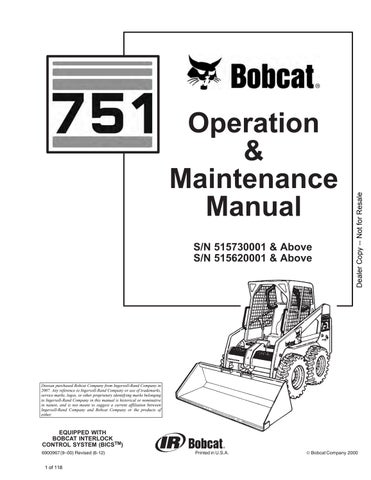
Option and Field Accessory Panels (If Equipped)
Side Accessory Panel [A] and [B]
Ref.
No.DescriptionFunction / Operation
1. POWER PLUGProvides a 12V receptacle for accessories.
2. NOT USED – – –
3. FRONT WIPERPress the top of the switch to start the front wiper (press and hold for washer fluid). Press the bottom of the switch to stop the wiper.
4. REAR WIPERPress the bottom of the switch to start the rear wiper. Press the top of the switch to provide washer fluid to clean the rear window.
5. NOT USED – – –
6. NOT USED – – –
7. FAN MOTORTurn clockwise to increase fan speed; counterlockwise to decrease. There are four positions; OFF – 1 – 2 – 3.
8. NOT USED – – –
9. TEMPERATURETurn clockwise to increase the CONTROLtemperature; counterclockwise to decrease.
Front Accessory Panel [C]
Ref.
No.DescriptionFunction / Operation
10. NOT USED – – –
11. NOT USED – – –
12. TURN SIGNAL Indicates left or right TURN INDICATORSSIGNALS are ON.
13. HAZARD Press the left side to turn the LIGHTSHAZARD LIGHTS ON; right side to turn OFF.

14. ROTATING Press the left side to turn the BEACONROTATING BEACON ON; right side to turn OFF.
Cab Light
Push the button (Item 1) [D] to turn the light ON. Push the button again to turn OFF.
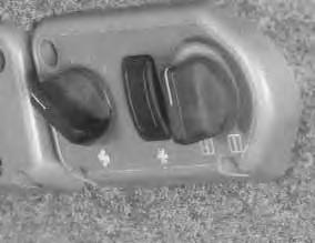
LIFT ARM BY–PASS CONTROL
The lift arm by–pass control (Item 1)[A] is used to lower the lift arms if the lift arms cannot be lowered during normal operations.
• Sit in the operator’s seat.
• Fasten the seat belt and lower the seat bar.
• Turn the knob (Item 1) [A] clockwise 1/4 turn.
• Pull up and hold the knob until the lift arms slowly lower.
Traction Lock Override
4.
(Functions Only When The Seat Bar Is Raised And The Engine Is Running) There is a TRACTION LOCK OVERRIDE Button (Item 1) [B] on the left instrument panel which will allow you to use the steering levers to move the loader forward & backward when using the backhoe attachment or for loader service.
• Press the TRACTION LOCK OVERRIDE Button once to unlock traction drive. The TRACTION light (Item 2) [B] will be ON.
• Press the button a second time to lock the traction drive. The TRACTION light (Item 2) [B] will be OFF.
NOTE:The TRACTION LOCK OVERRIDE Button will unlock the traction drive when seat bar is raised and the engine is running.
The TRACTION LOCK OVERRIDE Button will function if brake pedal is in the engaged or disengaged position and the engine is running.
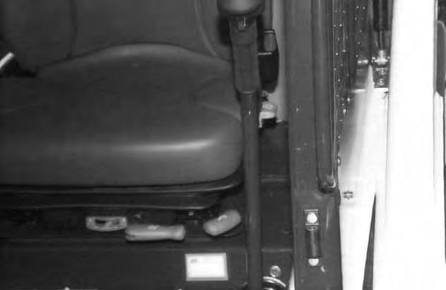
Engine Speed Control
The speed control lever is at the right sideof the operator’s seat (Item 1) [A]

Move the lever forward to increase engine speed. Move backward to decrease engine speed.
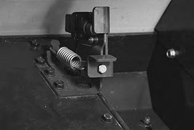

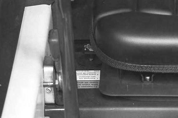
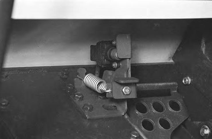
Parking Brake
Push on the top of the pedal [B] to engage the parking brake. The traction drive system will be locked.
Push on the bottom of the pedal [C] to release the parking brake. The traction drive system will be unlocked. *
NOTE:* The TRACTION light on the left instrument panel will remain OFF until the engine is started, the PRESS TO OPERATE LOADER Button is pressed and the parking brake is disengaged.
Steering Levers
When operating the machine:
• Keep the seat belt fastened snugly.
• The seat bar must be lowered.
• Keep your feet on the pedal controls or footrests and hands on steering levers.
W–2261–0799
The steering levers (Item 1)[A] are on the left and right side in front of the seat.

Move levers smoothly. Avoid sudden starting and stopping. The steering levers control forward and reverse travel and turning the loader [B]
Forward Travel – Push both levers forward.
Reverse Travel – Pull both levers backward.
Normal Turning – Move one lever farther forward than the other.
Fast Turning – Push one lever forward and pull the other lever backward.
For slow travel speed, push the steering levers forward only a small amount.
To increase travel speed, push both levers farther forward. For maximum pushing force, push the levers forward only a small amount with the engine at full speed.
STOPPING THE BOBCAT LOADER
When the steering levers are moved tothe neutral position, the hydrostatic transmission will act as a service brake to stop the loader.
Left Turn
Reverse
Left Fast Turn Right Fast Turn
Seat Bar Restraint System
The seat bar restraint system has a pivoting seat bar with arm rests (Item 1) [A]
The operator controls the use of the seat bar. The seat bar in the down position helps to keep the operator in the seat.
Avoid Injury Or Death
When operating the machine:
• Keep the seat belt fastened snugly.
• The seat bar must be lowered.
• Keep your feet on the pedal controls or footrests and hands on steering levers.
When the seat bar is down, PRESS TO OPERATE LOADER Button is activated, and the brake pedal is released, the lift, tilt, and traction drive functions can be operated. (Traction drive will operate only when the engine is running.)

When, the seat bar is up, the lift, tilt, and traction drive functions are deactivated and both foot pedals (ifequipped) will be locked when returned to neutral position.
Before you leave the operator’s seat:
• Lower the lift arms, put the attachment flat on the ground.
• Stop the engine.
• Engage the parking brake.
• Raise seat bar.
• (Foot Pedal Controls) Move pedals until both lock.
• (Advanced Hand Controls) Move the hand controls to the NEUTRAL POSITION to make sure that both lift and tilt functions are deactivated.
The seat bar system must deactivate the lift and tilt control functions when the seat bar is up. Service the system if hand controls do not deactivate.
W–2327–0798
Hydraulic Controls
Put your feet on the pedals (or footrests) and KEEP THEM THERE any time you operate the loader.
Two foot pedals (or hand controls) (Item 1) [A] and [B] control the hydraulic cylinders for the lift and tilt functions.
Foot Pedals
Lift Arm Operation [A]
The left pedal controls the lift arms.
Push on the bottom (heel) (Item 2) [A] of the pedal to raise the lift arms.
Push on the top (toe) (Item 3) [A] of the pedal to lower the lift arms.
Lift Arm Float Position [A]
Push the top (toe) (Item 3) [A] of the pedal all the way forward until it locks into the float position
Use the float position of the lift arms to level loose material while driving backward.
Push the bottom of the left pedal to unlock from thefloat position.
Tilt Operation [B]
The right pedal controls the bucket.
Push the bottom (heel) (Item 2)[B] of the pedal to tilt the bucket backward.
Push the top (toe) (Item 3) [B] of the pedal to tilt the bucket forward.
Advanced Hand Controls (If Equipped)
Lift Arm Operation [A]
The left hand lever controls the lift arms.
Move the left hand lever away from the operator (Item 4) [A] to raise the lift arms.
Move the left hand lever toward the operator (Item 5) [A] to lower the lift arms.
Lift Arm Float Position [A]
Move the left hand lever all the way toward the operator (Item 5) [A] until it locks into the float position.
Later AHC Models With Float Button
– Press anbd hold the Float Button (Item 6) [A] before moving the lever.
– Press again to disengage.
Use the float position of the lift arms to level loose material while driving backward.
Move the left hand lever upward to unlock from thefloat position.
Tilt Operation [B]
The right hand lever controls the bucket.
Move the right hand lever toward the operator (Item 5) [B] to tilt the bucket backward.
Move the right hand lever away from the operator (Item 4) [B] to tilt the bucket forward.
Keep both feet on pedals or footrests while operating machine. Failure to do so can cause serious injury.
HYDRAULIC CONTROLS (Cont’d)
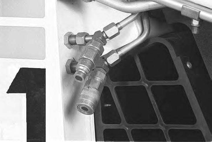
Quick Couplers
To Connect: Remove dirt or debris from the surface of both the male and female couplers, and from the outside diameter of the male coupler. Visually check the couplers for corroding, cracking, damage, or excessive wear. If any of these conditions exist, the coupler(s) must be replaced [A] and [B]
Install the male coupler into the female coupler. Full connection is made when the ball release sleeve slides forward on the female coupler and the sleeve is rotated so that the locking pins (Item 3) [C] and the grooves (Item 2) [C] do NOT align (Locked Position).

To Disconnect: Rotate the ball release sleeve so that the grooves are aligned with the pins (Item 1)[C] in the female coupler.
Hold the male coupler. Retract the sleeve on the female coupler until the couplers disconnect.

NOTE:If the locking pins and grooves (Item 3) [C] are aligned, accidental disconnection is possible.
Avoid Burns
Hydraulic fluid, tubes, fittings and quick couplers can get hot when running machine and attachments. Be careful when connecting and disconnecting quick couplers.
W–2220–0396
Releasing Hydraulic Pressure (Loader and Attachment)
5.
Loader:
• Press the AUXILIARY PRESSURE RELEASE Button (Item 1) [D]. Hold it for two seconds. The engine will stop and release hydraulic pressure.
• Pressing the AUXILIARY HYDRAULIC RELEASE Button after pressing the RUN / ENTER Button, when the engine is stopped, will also release hydraulic pressure.

Attachments:
• Follow procedure above to release pressure in loader.
• Connect male coupler from attachment to female coupler of loader then repeat procedure above. This will release pressure in the attachment.
• Connect the female coupler from the attachment.
Hydraulic pressure in the auxiliary hydraulic system can make it difficult to engage quick couplers to an attachment.
HYDRAULIC CONTROLS (Cont’d.)
6.
Attachment Auxiliary Hydraulics (If Equipped)
Auxiliary Hydraulics Button

• Variable Flow – (Front Aux. Hyd. Only)
Variable Flow allows for slow–to–fast movement of auxiliary functions. If you move the auxiliary switch (Item 1) [B] half way, the auxiliary functions move at approximately one–half speed.
Press the AUXILIARY HYDRAULICS Button (Item 1) [A] once.
The light (Item 2) [A] will be ON.
• Maximum Flow Only
Maximum Flow allows for fast movement only. If you move the auxiliary switch (Items 1 or 3) [B], the auxiliary functions move at fast speed; release the switch to stop auxiliary functions.
Press the AUXILIARY HYDRAULICS Button (Item 1) [A] a second time.
The light (Items 3) [A] will be ON.
• Disengage
Press the AUXILIARY HYDRAULICS Button (Item 1) [A] a third time.
Both lights (Items 2 & 3) [A] will be OFF.
NOTE:When the operator is seated and raises the seat bar, the Auxiliary Hydraulic System (Front and Rear) will deactivate.
FRONT Auxiliary Hydraulics Operation (RIGHT Steering Lever)
Variable Flow
• Press the AUXILIARY HYDRAULICS Button for Variable Flow (See above).
• Push the switch (Item 1) [B] to the right or left to change the fluid flow direction to the front quick couplers. (EXAMPLE: Open and close grapple teeth.)
Maximum Flow Only
• Press the AUXILIARY HYDRAULICS Button for Maximum Flow (See above.)
Continuous Flow
• After selecting Variable or Maximum Flow, press the front switch (Item 2) [B] to give the front quick couplers a constant flow of fluid with the female coupler being pressurized. (EXAMPLE: Operate a backhoe.) To set reverse flow (male coupler pressurized), hold the auxiliary switch (Item 1) [B] to the left, press Variable or Maximum Flow and then press the front switch (Item 2) [B] Reverse flow can be used only with augers, power rakes, sweepers, tillers, and vibratory rollers.
• To release from continuous operation, press the front switch (Item 2) [B] a second time.
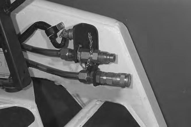
REAR Auxiliary Hydraulics Operation (LEFT Steering Lever)

• Press the AUXILIARY HYDRAULICS Button for Maximum Flow (See above).
• Push the switch (Item 3) [B] to the right or left to change the fluid flow direction to the rear quick couplers [C]. (EXAMPLE: Raise and lower rear stabilizers.)
HYDRAULIC CONTROLS (Cont’d.)
Attachment Control Device (ACD) (If Equipped)

When this kit is installed (Item 1)[A], the ACD Icon light [B] on the right instrument panel will be ON when a 7–pin electric controlled attachment is installed.
You will need the Dual–Connector (7 pin/14 pin) Kit (Inset) [A] to operate early model attachments. See your Bobcat loader dealer.
You can then use additional switches (Items 1 thru 4) [C] on the right and left control handles for functions which control some attachments.
See the appropriate Attachment Operation &Maintenance Manual for control details.
NOTE:When the Optional / Field Accessory Dual–Conector (7 pin / 14 pin) Kit (Inset [A] is installed, the ACD Icon light will be ON when the dual connector switch is in the 14 pin position. Always put the switch in the 7–pin position when no attachment is connected.

Diesel fuel or hydraulic fluid under pressure can penetrate skin or eyes, causing serious injury or death. Fluid leaks under pressure may not be visible. Use a piece of cardboard or wood to find leaks. Do not use your bare hand. Wear safety goggles. If fluid enters skin or eyes, get immediate medical attention from a physician familiar with this injury.
W–2072–0496
Bucket Position Valve Operation (If Equipped)
The function of the bucket position valve is to keep the bucket in the same approximate position it is in before you begin raising the lift arms.
Press BUCKET POSITIONING Button (Item 1) [D] to engage the bucket positioning function. (The light will be ON.) Press again to disengage.
Bucket Positioning functions only during the upward lift cycle.
Shutdown Feature
Press and hold the BUCKET POSITIONING Button (Item 1) [D] for 2 seconds. If the SHUTDOWN feature isinstalled, Shtdn will appear in the HOURMETER/CODE DISPLAY (Item 2) [D]. If it is not installed, BASE will appear. (Operational Code will appear first).
Daily Inspection
Maintenance work must be done at regular intervals. Failure to do so will result in excessive wear and early failures. The Service Schedule [A] is a guide for correct maintenance of the Bobcat loader. It is located inside the rear door of the loader and also in the MACHINE SIGN TRANSLATION Section Page 79.
Daily Inspection and Maintenance:
• Engine Oil Level
• Hydraulic/Hydrostatic Fluid Level
• Engine Air Filter, Check Air System for Damage or Leaks
• Engine Coolant Level, Check System for Damage or Leaks
• Operator Cab and Cab Mounting Hardware
• Seat Belt
• Seat Bar and Control Interlocks
• Grease Pivot Pins (Lift Arms, Bob–Tach, Cylinders, Bob–Tach Wedges)
• Tires, Check for Wear, Damage, Correct Air Pressure
• Fuel Filter, Remove Trapped Water
• Loose or Broken Parts, Repair or replace as necessary
• Safety Treads and Safety Signs (Decals), Replace as necessary
• Lift Arm Support Device. Replace if damaged
• Bobcat Interlock Control System (BICS ™)
W–2001–0596
NOTE:Fluids such as engine oil, hydraulic fluid, coolant, etc. must be disposed of in an environmentally safe manner. Some regulations require that certain spills and leaks on the ground must be cleaned in a specific manner. See local, state and federal regulations for correct disposal.
PRE–STARTING PROCEDURE
7.
Use the bucket or attachment steps, grab handles and safety treads (on top of the loader lift arms and frame) to get on and off the loader [A]. Do not jump.
Safety treads are installed on the Bobcat loader toprovide a slip resistant surface for getting on and off the loader. Keep safety treads clean and replace when damaged. Replacement treads are available from your Bobcatloader dealer.

Read and understand the Operation & Maintenance Manual and the Operator’s Handbook (Item 1) [A] before operating the loader.
The Operation & Maintenance Manual and other manuals can be kept in a container (Item 2)[A] provided behind the operator seat.

Instructions are necessary before operating or servicing machine. Read and understand the Operation & Maintenance Manual, Handbook and signs (decals) on machine. Follow warnings and instructions in the manuals when making repairs, adjustments or servicing. Check for correct function after adjustments, repairs or service. Failure to follow instructions can cause injury or death [A].
W–2003–1298
Release the seat lever (Item 1) [B] and adjust the seat position for comfortable operation of the loader controls.

Suspension Seat – (If Equipped) Release the lever (Item 1) [C] to adjust the seat distance from the steering levers and foot pedals (if equipped). Release the lever (Item 2) [C] to adjust the angle of the seat back.Turn the lever (Item 3) [C] to adjust the seat cushion for weight of the operator.
Squeeze both seat belt adjusters to release and lengthen each half of the seat belt [D].
Fasten the seat belt.
Pull the ends of the belt through the belt adjusters so that the seat belt is snug and the buckle is centered between your hips [D]

Avoid Injury Or Death
When operating the machine:
• Keep the seat belt fastened snugly.
• The seat bar must be lowered.
• Keep your feet on the pedal controls or footrests and hands on steering levers.
W–2261–0799
PRE–STARTING PROCEDURE (Cont’d)
Lower the seat bar [A].


.

STARTING THE ENGINE
Standard Instrument Panel (With Key Switch) 8.
Perform the PRE–STARTING PROCEDURE Page 16.
Set the engine speed control to the 1/2 speed position[A].
Turn the key switch to RUN [B]. The indicator lights on the right instrument panel [B] will come ON briefly and the Instrument Panel / monitoring system will do a self test.
If the temperature is cold, the glow plugs willautomatically cycle. The Glow Plug Icon light (Item 1) [B] will be ON and the cycle time remaining will show in the hourmeter.
When the Glow Plug Icon light goes OFF, turn the key switch to START [B]
Advanced Hand Controls Only: Make sure both hand controls are in neutral before starting the engine. Do not move the Advanced Hand Control levers from the neutral position when turning the key to RUN or START [B].
If either hand control is moved: a.The neutral position for the hydraulic valve spool and hand control may not be correctly calibrated. This can result in movement of the lift or tilt hydraulic cylinders when the hand control lever is returned to the neutral position after start–up.
OR b.AHC indicator light (Item 2) [B] on right instrument panel will be ON.
If either condition occurs, return key to STOP [B]. Put the controls in neutral position and re–start the engine.
Do not engage the starter for longer than 15 seconds at a time. Longer use can damage the starter by overheating. Cool the starter for one minute between uses.
STARTING THE ENGINE (Cont’d)
Standard Instrument Panel (Cont’d)
Release the key when the engine starts. It will return to the RUN position.
Press the PRESS TO OPERATE LOADER Button (Item 1) [A] to activate the BICS system and to perform hydraulic and loader functions.
See Cold Temperature Starting, Page 22.
Avoid Injury Or Death
• Engines can have hot parts and hot exhaust gas. Keep flammable material away.
• Do not use machines in atmosphere containing explosive gas.
When an engine is running in an enclosed area, fresh air must be added to avoid concentration of exhaust fumes. If the engine is stationary, vent the exhaust outside. Exhaust fumes contain odorless, invisible gases which can kill without warning.
STARTING THE ENGINE (Cont’d)
Deluxe Instrument Panel (With Keyless Start)
Perform the PRE–STARTING PROCEDURE, Page 16. Set the engine speed control to the 1/2 speed position[A].
NOTE:Loaders with Deluxe Instrument Panel have a permanent, randomly generated Master Password set at the factory. Your loader will be assigned an Owner Password. Your dealer will provide you with this password. Change the password to one that you will easily remember to prevent unauthorized use of your loader.
(See SYSTEM SETUP & ANALYSIS Page 73.) Keep your password in a safe place for future needs.
Use the numeric keypad (Item 1)[B] to enter the password, then press the RUN / ENTER Button (Item 2) [B]
If the temperature is cold, the glow plugs willautomatically cycle and the Glow Plug Icon light (Item 3) [B] will be ON. When the Glow Plug Icon light goes OFF, press the START Button (Item 4) [B]. Release the button when the engine starts.
Advanced Hand Controls Only: Make sure both hand controls are in neutral before starting the engine. Do not move the Advanced Hand Control levers from the neutral position when pressing the RUN / ENTER Button.
If either hand control is moved: a.The neutral position for the hydraulic valve spool and hand control may not be correctly calibrated. This can result in movement of the lift or tilt hydraulic cylinders when the hand control lever is returned to the neutral position after start–up. OR b.AHC indicator light (Item 5) [B] on right instrument panel will be ON.
If either condition occurs, press the STOP Button. Put the controls in neutral position and re–start the engine.
Do not engage the starter for longer than 15 seconds at a time. Longer use can damage the starter by overheating. Cool the starter for one minute between uses.
I–2034–0284
STARTING THE ENGINE (Cont’d)
Deluxe Instrument Panel (Cont’d)
Release the START Button when the engine starts.
Press the PRESS TO OPERATE LOADER Button (Item 1) [A] to activate the BICS system and to perform hydraulic and loader functions.
See Cold Temperature Starting, Page 22.
• Engines can have hot parts and hot exhaust gas. Keep flammable material away.
• Do not use machines in atmosphere containing explosive gas.
W–2051–1086
When an engine is running in an enclosed area, fresh air must be added to avoid concentration of exhaust fumes. If the engine is stationary, vent the exhaust outside. Exhaust fumes contain odorless, invisible gases which can kill without warning.
W–2050–1285
STARTING THE ENGINE (Cont’d) Cold Temperature Starting
Do not use ether with glow plug (preheat) systems. Explosion can result which can cause injury or death.
9.
If the temperature is below freezing, perform the following to make starting the engine easier:
• Replace the engine oil with the correct type and viscosity for the anticipated starting temperature. (See ENGINE LUBRICATION SYSTEM Page 54.)
• Make sure the battery is fully charged.
• Install an engine heater, available from your Bobcat loader dealer.
NOTE:The LCD of the Deluxe Panel may not be immediately visible when the temperature is below –15°F (–26°C). It may take 30 seconds to several minutes for the Display Panel to warm up. All systems remain monitored even when the display is off.
Warming the Hydraulic/Hydrostatic System
When the temperature is below –20°F. (–30°C.), hydrostatic oil must be warmed before starting. The hydrostatic system will not get enough oil at low temperatures and will be damaged. Park the machine in an area where the temperature will be above 0°F. (–18°C.) if possible.
I–2007–1285
Let the engine run for a minimum of 5 minutes to warm the engine and hydrostatic transmission fluid before operating the loader.
If the Fluid Pressure Icon light (Item 1)[A] (Standard Panel) or [B] (Deluxe Panel) comes ON when operating the loader (cold), more warm up time is needed.
Stopping The Engine
Pull the engine speed control fully backward [C] to decrease the engine speed.
Turn the key switch to the STOP position [A] (Standard Panel) or press the STOP Button (Item 2) [B] (Deluxe Panel).
MONITORING THE DISPLAY PANEL 10.
After the engine is running, frequently monitor the right instrument panel [A] (Standard Panel) and [B] (Deluxe Panel) for error conditions.
The associated Icon will be ON if there is an error condition.
EXAMPLE: Engine Coolant Temperature is High.
Standard Panel
The Engine Temperature Icon (Item 1) [A] will come ON.
Press and hold the LIGHTS Button for 2 seconds and one of the following SERVICE CODES will be displayed in the hourmeter / code display:
08–10 Engine Coolant Temperature High or 08–11 Engine Coolant Temperature Very High
Deluxe Panel
The Engine Temperature Icon (Item 1) [B] will be ON. The SERVICE CODE will be in the hourmeter / code display (see above).
In addition, the Deluxe Panel display screen will describe the extreme condition that can cause damage to the engine or loader systems [B].
WARNING AND SHUTDOWN:
When a WARNING condition exists, the associated Icon light will come ON and there will be 3 beeps from the alarm. Be aware that, if this condition is allowed to continue, there may be damage to the engine or loader hydraulic systems.
When a SHUTDOWN condition exists, the associated Icon light will come ON and there will be a continuous beep from the alarm and the monitoring system will automatically stop the engine in 10 seconds.
NOTE:The engine can be restarted to move or relocate the loader.
The SHUTDOWN feature is included with the Deluxe Right Panel or a Factory Option withthe Standard Panel.
The SHUTDOWN feature is associated with the following Icons:
General Warning
Engine Oil Pressure
Engine Coolant Temperature
Hydraulic Oil Temperature
Whenever STOP appears on the display screen, lower the lift arms all the way, put the attachment flat on the ground and stop the engine to prevent damage to the engine or loader systems.
ENGINE COOLANT TEMP EXTREMELY HIGH
Attachments And Buckets
NOTE:Warranty is void if non–approved attachments are used on the Bobcat loader.
Never use attachments or buckets which are not approved by Bobcat. Buckets and attachments for safe loads of specified densities are approved for each model. Unapproved attachments can cause injury or death.
W–2052–1299
The dealer can identify, for each model loader, the attachments and buckets approved by Bobcat. The buckets and attachments are approved for Rated Operating Capacity and for secure fastening to the Bob–Tach.
The Rated Operating Capacity for this loader is shown on a decal in the operator cab. (SeeSPECIFICATIONS Page 89 )
The Rated Operating Capacity is determined by using a standard dirt bucket, and material of normal density, such as dirt or dry gravel. If longer buckets are used, the load center moves forward and reduces the Rated Operating Capacity. If very dense material is loaded, the volume must be reduced to prevent overloading.
Exceeding the Rated Operating Capacity [A] can cause the following problems:
• Steering the loader may be difficult.
• Tires will wear faster.
• There will be a loss of stability.
• The life of the Bobcat loader will be reduced. Use the correct size bucket for the type and density of material being handled. For safe handling of materials and avoiding machine damage, the attachment (or bucket) should handle a full load without going over the Rated Operating Capacity for the loader. Partial loads make steering more difficult.
Maximum load to be carried when using a pallet fork is shown in figure [B]
See your Pallet Fork Operation & Maintenance Manualfor more information about pallet fork inspection, maintenance and replacement. See your Bobcat loader dealer for other available attachments.
ATTACHMENTS AND BUCKETS (Cont’d)
Bob–Tach
Installing The Bucket Or Attachment
The Bob–Tach is used for fast changing of buckets and attachments. See the appropriate Attachment Operation & Maintenance Manual to install other attachments.
Pull the Bob–Tach levers all the way up (Item 1) [A]
Enter the loader and perform the PRE–STARTING PROCEDURE page 16.
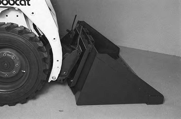
Lower the lift arms and tilt the Bob–Tach forward.
Drive the loader forward until the top edge of the Bob–Tach is completely under the top flange of the bucket [A] (or other attachment). Be sure the Bob–Tach levers do not hit the bucket.
Tilt the Bob–Tach backward until the cutting edge of the bucket (or other attachment) is slightly off the ground [B] Stop the engine and exit the loader.
Before you leave the operator’s seat:
• Lower the lift arms, put the attachment flat on the ground.
• Stop the engine.
• Engage the parking brake.
• Raise seat bar.
• (Foot Pedal Controls) Move pedals until both lock.
• (Advanced Hand Controls) Move the hand controls to the NEUTRAL POSITION to make sure that both lift and tilt functions are deactivated.
The seat bar system must deactivate the lift and tilt control functions when the seat bar is up. Service the system if hand controls do not deactivate.
W–2327–0798
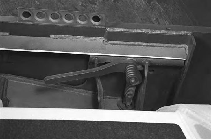
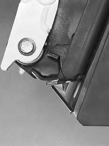
Push down on the Bob–Tach levers until they are fully engaged in the locked position (Item 1) [C] (wedges fully extended).
The wedges (Item 1) [D] must extend through the holes (Item 2) [D] in the mounting frame of the bucket (or attachment), securely fastening the bucket to the Bob–Tach.

Bob–Tach wedges must extend through the holes in attachment. Lever(s) must be fully down and locked. Failure to secure wedges can allow attachment to come off and cause injury or death.

W–2102–0497
ATTACHMENTS AND BUCKETS (Cont’d)
Bob–Tach (Cont’d)
Removing The Bucket Or Attatchment
Lower the lift arms and put the attachment flat on the ground and lower or close the hydraulic equipment.
• If the attachment is hydraulically controlled(combination bucket, backhoe, etc.), stop the engine and relieve hydraulic pressure in the auxiliary circuit (SeeReleasing Hydraulic Pressure, Page 12. Disconnect the auxiliary hydraulic hoses from the loader.
Raise the seat bar, unfasten the seat belt, set the parking brake and exit the loader.
Before you leave the operator’s seat:
• Lower the lift arms, put the attachment flat on the ground.
• Stop the engine.
• Engage the parking brake.
• Raise seat bar.
• (Foot Pedal Controls) Move pedals until both lock.
• (Advanced Hand Controls) Move the hand controls to the NEUTRAL POSITION to make sure that both lift and tilt functions are deactivated.
The seat bar system must deactivate the lift and tilt control functions when the seat bar is up. Service the system if hand controls do not deactivate.
W–2327–0798
Pull the Bob–Tach levers [A] all the way up.
Enter the loader.
Perform the PRE–STARTING PROCEDURE Page 16.
Start the engine.
Release the parking brake.
Press the PRESS TO OPERATE LOADER Button.
Be sure the lift arms are all the way down. Tilt the Bob–Tach forward.

Move the loader backward, away from the bucket or attachment [B]
Bob–Tach levers have spring tension. Hold lever tightly and release slowly. Failure to obey warning can cause injury.
Operating Procedure
When operating on a public road or highway, always follow local regulations. For example: Slow Moving Vehicle Sign or direction signals may be required.
Always warm the engine and hydrostatic system before operating the loader.
Machines warmed up with moderate engine speed and light load have longer life.
I–2015–0284
Operate the loader with the engine at full speed for maximum horsepower. Move the steering levers only a small amount to operate the loader slowly.
New operators must operate the loader in an open area without bystanders. Operate the controls until the loader can be handled at an efficient and safe rate for all conditions of the work area.
With a full bucket, go up or down the slope with the heavy end toward the top of the slope [A] & [B]
B With Bucket Full
With empty bucket, go down or up the slope with the heavy end toward the top of the slope [C] & [D].
C With Bucket Empty
• Keep the lift arms as low as possible.
• Do not travel or turn with the lift arms up.
• Turn on level ground.
• Go up and down slopes, not across them.
• Keep the heavy end of the machine uphill.
• Do not overload the machine.
Failure to obey warnings can cause the machine to tip or roll over and cause injury or death.
W–2018–1187
Raise the bucket only high enough to avoid obstructions on rough ground.
D With Bucket Empty
OPERATING PROCEDURE (Cont’d)
Filling the Bucket (Foot Pedals)
Push the top of the lift pedal (Item 1) [A] until the lift arms are all the way down.
Push the top of the tilt pedal (Item 2) [A] to put the cutting edge of the bucket on the ground.
Drive slowly forward into the material. Push thebottom of the tilt pedal (Item 1) [B] to raise the front of the bucket.
Drive backward away from the material.
Load, unload and turn on flat level ground. Do not exceed rated operating capacity shown on sign (decal) in cab. Failure to obey warnings can cause the machine to tip or roll over and cause injury or death.
Filling the Bucket (Advanced Hand Controls)
Move the left hand lever, from neutral position ( N), toward the operator (Item 3) [A] until the lift arms are all the way down.
Move the right hand lever, from neutral position ( N) away from the operator (Item 4) [A] to put the cutting edge of the bucket on the ground.
Drive slowly forward into the material. Move the right hand lever, from neutral position ( N), toward the operator (Item 2) [B] to raise the front of the bucket. Drive backward away from the material.
OPERATING PROCEDURES (Cont’d)
Emptying the Bucket (Foot Pedals)
Push the bottom of the lift pedal (Item 1)[A] to raise the lift arms. Push the top of the tilt pedal while raising the lift arms to level the bucket or attachment and help prevent material from falling off the back of the bucket or attachment.
Drive forward slowly until the bucket is over the top of the truck box or bin.
Push the top of the tilt pedal (Item 2)[A] until the bucket is empty. If all the material is near the side of the truck or bin, push it to the other side with the bucket.
Emptying the Bucket (Hand Controls)
Move the left hand lever, from neutral position (N), away from the operator (Item 3) [A] to raise the lift arms. Move the right hand lever, from neutral position ( N), away from the operator to level the bucket or attachment and help prevent material from falling off the back of the bucket or attachment.
Drive forward slowly until the bucket is over the top of the truck box or bin.
Move the right hand lever, from neutral position (N), away from the operator (Item 4) [A] until the bucket is empty. If all the material is near the side of the truck or bin, push it to the other side with the bucket.
Leveling the Ground (Using Lift Arms in Float Position) (Foot Pedals)
Push the top of the lift pedal (Item 1) [B] all the way forward until the pedal is in the locked position to put the lift arms in the float position.
Push the tilt pedal (Item 2)[B] to change the position of the cutting edge on the bucket.
With the bucket tilted farther forward, there is more force on the cutting edge and more loose material can be moved.
Drive backward to level loose material.
Push the bottom of the lift pedal to unlock from thefloat position.
Leveling the Ground (Using Lift Arms in Float Position) (Advanced Hand Controls)
Move the left hand lever, from neutral position ( N), all the way down and in (Item 3) [B] until the hand lever is in the locked position to put the lift arms in the float position.
Later AHC Models with Float Button
–Press and hold the float button (Item 5) [B] before moving lever.
–Press again to disengage.
Move the right hand lever, from neutral position (N), away from the operator (Item 4) [B], to change the position of the cutting edge on the bucket.
With the bucket tilted farther forward, there is more force on the cutting edge and more loose material can be moved.
Drive backward to level loose material.
Move the left hand lever upward to unlock from thefloat position.
Never dump over an obstruction, such as a post, that can enter the operator cab. The machine could tip forward and cause injury or death.
Never drive forward when the hydraulic control for lift arms is in float position.
OPERATING PROCEDURES (FOOT PEDALS) (Cont’d)
Digging Into the Ground
(Foot Pedals)
Put the lift arms all the way down. Push the top of the tilt pedal (Item 1) [A] until the cutting edge of the bucket is on the ground.
Drive forward slowly and continue to tilt the bucketdown (Item 1) [A] until it enters the ground.
Push the bottom of the tilt pedal a small amount to increase traction and keep an even digging depth. Continue to drive forward until the bucket is full. When the ground is hard, raise and lower the cutting edge of the bucket with the tilt pedal while driving forward slowly.
Push the bottom of the tilt pedal (Item 1) [B] to tilt the bucket backward as far as it will go when the bucket is full
Digging Into the Ground
(Advanced Hand Controls)
Put the lift arms all the way down. Move the right hand lever away from the operator (Item 2) [A] until the cutting edge of the bucket is on the ground. Drive forward slowly and continue to tilt the bucket down until it enters the ground .
Move the right hand lever toward the operator a small amount to increase traction and keep an even digging depth. Continue to drive forward until the bucket is full. When the ground is hard, raise and lower the cutting edge of the bucket with the hand lever while driving forward slowly.
Move the right hand lever toward the operator (Item 2) [B] to tilt the bucket backwards as far as it will gowhen the bucket is full .
Backfilling (Foot Pedals)
Lower the lift arms (Item 1)[C] and put the cutting edge of the bucket on the ground. Drive forward to the edge of the hole to push the material into the hole.
Tilt the bucket forward (Item 2) [C] as soon as it is past the edge of the hole.
If necessary, raise the lift arms to empty the bucket.
Backfilling (Advanced Hand Controls)
Lower the lift arms (Item 3)[C] and put the cutting edge of the bucket on the ground. Drive forward to the edge of the hole to push the material into the hole.
Tilt the bucket forward (Item 4) [C] as soon as it is past the edge of the hole.
If necessary, raise the lift arms to empty the bucket.
Parking The Bobcat Loader
Stop the Bobcat loader on level ground.
Lower the lift arms fully and put the attachment flat on the ground [A].
Pull the engine speed control lever all the way backward. Turn the key switch to STOP (Standard Panel) OR press the STOP Button ( Deluxe Panel).
Before you leave the operator’s seat:
• Lower the lift arms, put the attachment flat on the ground.
• Stop the engine.
• Engage the parking brake.
• Raise seat bar.
• (Foot Pedal Controls) Move pedals until both lock.
• (Advanced Hand Controls) Move the hand controls to the NEUTRAL POSITION to make sure that both lift and tilt functions are deactivated. The seat bar system must deactivate the lift and tilt control functions when the seat bar is up. Service the system if hand controls do not deactivate.
Engage the parking brake.
Lift the seat bar and make sure the lift and tilt functions are deactivated.
Unbuckle the seat belt.
Remove the key from the switch (Standard Panel) to prevent operation of the loader by unauthorized personnel.
Adequately designed ramps of sufficient strength are needed to support the weight of the machine when loading onto a transport vehicle. Wood ramps can break and cause personal injury.
W–2058–0494
Be sure the transport and towing vehicles are of adequate size and capacity (See SPECIFICATIONS Page 89, for weight of loader.)
A loader with an empty bucket or no attachment must be loaded backward onto the transport vehicle [A].
The rear of the trailer must be blocked or supported [A] when loading or unloading the loader to prevent the front end of the trailer from raising up.
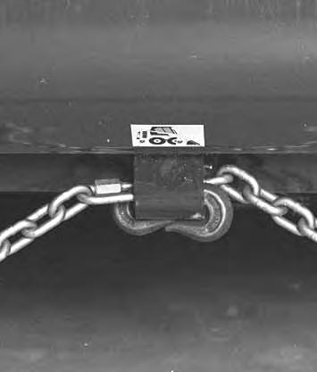
Use the following procedure to fasten the Bobcat loaderto the transport vehicle to prevent the loader from moving during sudden stops or when going up or down slopes[B]
• Lower the bucket or attachment to the floor.
• Stop the engine.
• Engage the parking brake.
• Install chains at the front and rear loader tie down positions (Inset) [B]

• Fasten each end of the chain to the transport vehicle.
Towing The Loader
To prevent damage to the loaders hydrostatic system, the loader must be towed only a short distance at slow speed. (Example: Moving the loader onto a transport vehicle). The towing chain (or cable) must be rated at 1 & 1/2 times the weight of the loader. (See SPECIFICATIONS Page 89 )

• Turn the key switch to RUN (Standard Panel) OR press the RUN / ENTER Button ( Deluxe Panel).
• Press the TRACTION LOCK OVERRIDE Button.
• Tow the Bobcat at 2 MPH (3,2 km/hr) or less for not more than 25 feet (7,6 meters).
If the electrical system is not functioning, contact your Bobcat loader dealer.

Lifting The Loader
Single Point Lift
Avoid Injury Or Death
• Before lifting, check fasteners on single point lift and operator cab.
• Assemble front cab fasteners as shown in this manual.
• Never allow riders in the cab or bystanders within 15 feet (5 meters) while lifting the machine.
W–2007–0497
Lift the loader with the single point lift which is available as a kit from your Bobcat loader dealer.
Attach cables or chains to the single point lift as shown[A]
The single point lift, supplied by Bobcat is designed to lift and support the Bobcat loader without affecting roll over and falling object protection features of the operator cab.