14 minute read
MACHINE SIGNS (DECALS) (Cont’d)


Instrument Panel
The instrument panel has the following instruments [A]
1.LIGHT SWITCH (OPT.) – Controls the work and travel lights.
2.IGNITION SWITCH – For starting, stopping and ‘‘pre–heating’’ the engine.
3.FUSE (ACCESSORIES) – To protect the electrical system from overload.
4.FUSE (IGNITION) – To protect the electrical system from overload.
5.HOURMETER – Records the total operating hours of the loader.
6.FUEL GAUGE – Shows the amount of fuel in the fuel tank.
7.ENGINE TEMPERATURE GAUGE – Shows the engine coolant temperature.
8.ENGINE WARNING LIGHT – Engine oil pressure is low. Stop the engine if the light comes ‘‘ON’’.
9.TRANSMISSION WARNING LIGHT – Low transmission charge pressure, hydraulic filter needs replacement or high fluid temperature. Stop the engine if the light comes ‘‘ON’’.
10.VOLTMETER – Shows the condition of the battery and the rate of charge.
Engine Speed Control
The engine speed control (Item 1) [B] is at the right side of the operator’s seat. Engine speed is controlled by moving the engine speed control forward to increase the engine RPM and backward to decrease the engine RPM.
Engine Stop Control
The engine stop control (Item 2) [B] is located near the engine speedcontrol. Pull up on the engine stop control to stop the engine. Push down on the control after the engine is stopped.
Parking Brake
Lock the parking brake by pushing down on the top (toe) of the pedal [A].
To release the parking brake, push down on the bottom (heel) of the pedal [B].
Avoid Injury Or Death
When operating the machine:
• Keep the seat belt fastened snugly.
• The seat bar must be lowered.
• Keep your feet on the pedal controls.
W–2046–0595
The steering levers (Item 1) are on the right and left side in front of the seat [A]
For safe control of the loader always move the levers slowly and smoothly. Only a small movement is necessary to move the loader.
The steering levers control forward and reverse travel of the loader [B]
FORWARD TRAVEL : Push both levers forward.
REVERSE TRAVEL : Pull both levers backward.
NORMAL TURNING: Move one lever farther forward than the other.
FAST TURNING: Push one lever forward and pull the other lever backward.
For slow travel speed, push the levers forward only a small amount.
To increase travel speed, push the levers farther forward.
For maximum pushing force, push the levers forward only a small amount with the engine at full RPM.
Backward
Left Turn
Right Turn
Fast Turnfast Turn
Hydraulic Controls
Foot Pedals
Keep both feet on pedals while operating machine. Failure to do so can cause serious injury.
W–2002–1285
Put your feet on the pedals and KEEP THEM THEREany time you operate the loader.
Two foot pedals (Item 1) [A] control the hydraulic cylinders for the tilt and lift function.
Lift Arm Operation
The left pedal controls the lift arms. Push on the bottom (heel) (Item 2) [A] of the pedal to raise the lift arms.
Push on the top (toe) (Item 3)[A] of the pedal to lower the lift arms. Use the Float position of the lift arms to level loose material while driving backward.
The optional bucket position valve, will keep the bucket at a level position when the lift arms are being raised.
Tilt Operation (Bucket)
The right pedal controls the action of thebucket. Push the top (toe) (Item 4) [A] of the pedal to tilt the bucket forward.
Push the bottom (heel) (Item 5) [A] of the pedal to tilt the bucket backward.
HYDRAULIC CONTROLS (Cont’d)
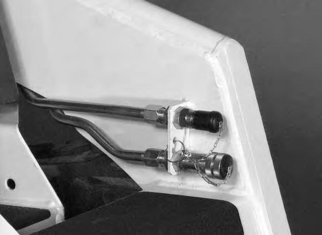
Auxiliary Hydraulics Operation (Optional)
The right steering lever is also the control lever for the front auxiliary hydraulics [A]
Move the right steering lever to the left or to the right to activate the auxiliary hydraulics and operate an attachment (Example: To open or close grapple teeth). Move the lever in the opposite direction to reverse the action of the attachment [B]
Move the steering lever all the way to the right (Item 1)[B] to put the control valve into the detent position for a constant flow of hydraulic fluid under pressureto the quick couplers.
NOTE:See Page 50 to remove auxiliary control lockbolt.
Daily Inspection
The loader must be in good operating condition [A].
Check the following items:
* Engine Oil
* Hydraulic/Hydrostatic Fluid
* Air Cleaner Condition Indicator
* Engine Cooling System *
* Operator Cab, Seat Belt, Seat Bar & Pedal Interlocks
* Lift Arms & Cylinder Pivot Pins
* Tires & Tire Pressure
* Any Loose or Broken Parts
* Safety Tread & Safety Signs
Follow the maintenance requirements on the Service Schedule Decal, located inside the rear door [B].
Instructions are necessary before operating or servicing machine. Read and understand the Operation & Maintenance Manual, Handbook and signs (decals) on machine. Follow warnings and instructions in the manuals when making repairs, adjustments or servicing. Check for correct function after adjustments, repairs or service. Untrained operators and failure to follow instructions can cause injury or death. W–2003–0199
Seat Bar Restraint System
The seat bar restraint system has a pivoting seat bar (Item 1) with arm rests and has spring loaded interlocks for the lift and tilt control pedals. Theoperator controls the use of the seat bar. The seat bar in the down position helps to keep the operator in the seat. The interlocks require the operator to lower the seat bar in order to operate the foot pedal controls. When the seat bar is up, the lift and tilt control pedals are locked when returned to the neutral position [A]
AVOID INJURY OR DEATH
When operating the machine:
• Keep the seat belt fastened snugly.
• The seat bar must be lowered.
• Keep your feet on the pedal controls.
W–2046–0595
The spring loaded interlocks (Item 1) [A] control the locking and unlocking functions of the control pedals.
The interlocks (Item 1) [B] require the operator to lower the seat bar (Item 2) [B] which allows the operator to move the foot pedals to control the lift and tilt functions.
When the seat bar is lowered, it pushes the interlock (Item 1) [B] down on both sides, releasing the pedal linkages (Item 3) [B] from the interlocks.
The pedals now pivot in both directions when the interlock is down.
AVOID INJURY OR DEATH
Before you leave the operator’s seat:
• Lower the lift arms, put the attachment flat on the ground.
• Stop the engine.
• Engage the parking brake.
• Raise seat bar, move pedals until both lock.
W–2045–1086
AVOID INJURY OR DEATH
The seat bar system must lock the lift and tilt control pedals in neutral when the seat bar is up. Service the system if pedals do not lock correctly.
W–2105–1285
When the seat bar is raised, spring forces raise the interlocks [C].
The foot pedals will not pivot when the interlock is up.
Refer to the Preventive Maintenance section for Seat Bar Restraint System Inspection & Maintenance.

Getting Ready For Operation
Read this Operation & Maintenance Manual and the Operator’s Handbook before operating the loader [A]
Operator must have instructions before running the machine. Untrained operators can cause injury or death.
W–2001–0596
Use the bucket or attachment steps, grab handles and safety tread (on top of the loader lift arm crossmember and main frame) to get on and off the loader [B]
Safety treads are installed on the Bobcatloader to provide a slip resistant surface for getting on and off the loader. Keep the safety treads clean and replace when damaged. Replacement treads are available from your dealer.
Pull the seat lever (Item 1)[C] and adjust the seat position for comfortable operation of the loader controls.
Fasten the seat belt snugly and adjust it so that the buckle is centered between the hips [D].
AVOID INJURY OR DEATH
When operating the machine:
• Keep the seat belt fastened snugly.
• The seat bar must be lowered.
• Keep your feet on the pedal controls.
W–2046–0595
GETTING READY FOR OPERATION (Cont’d)
Lower the seat bar [A]
Be sure the parking brake is engaged.
All controls must be in the neutral position before you start the engine (See Normal Starting Condition, Page 9).
Keep feet on the pedals while seated in the loader [B].
Starting The Engine
W–2050–1285
When an engine is running in an enclosed area, fresh air must be added to avoid concentration of exhaust fumes. If the engine is stationary, vent the exhaust outside. Exhaust fumes contain odorless, invisible gases which can kill without warning [C].
AVOID INJURY OR DEATH
* Engines can have hot parts and hot exhaust gas. Keep flammable material away.
* Do not use machines in atmosphere containing explosive gas [D].
W–2051–1086
Normal Starting Condition
Adjust the seat position for comfortable operation of the foot pedals and steering levers.
Fasten the seat belt snugly and adjust it so the buckle is centered between the hips.
STARTING THE ENGINE (Cont’d)
Lower the seat bar [A]
Put the foot pedals and steering levers in neutral (center) position (Item 1) [B].
Be sure the parking brake is engaged. Set the engine speed control to the half speed position (Item 2) [B]
Turn the key to the ‘‘ON’’ position. The engine and transmission warning lights must be ‘‘ON’’ when the key is on and the engine is stopped (Item 3) [B]
Turn the key to the start position (Item 4) and release it when the engine starts [B].
Do not engage starter for longer than 15 seconds at at time. Longer use can damage starter by overheating. Cool starter for one (1) minute between uses.
When the engine starts, release the key and it will return to the run position (Item 5) [B]
STOP THE ENGINE IF THE WARNING LIGHTS DO NOT GO OFF.
In cold starting conditions, turn the key all the way to the left for ‘‘PRE–HEAT’’ position (Item 6) [B]. See also Cold Starting Condition, Page 13.
STARTING THE ENGINE (Cont’d) Cold Temperature Starting Condition
If the temperature is below 32oF. (0oC.), use the following procedure to make starting the engine easier:
1.Replace the engine oil with the correct type and viscosity for the anticipated starting temperature (See ‘‘Oil Specifications’’, Page 31).
2.Make sure the battery is at full charge.
3.Install a block or tank heater on the engine. Follow the steps under ‘‘Normal Starting Condition’’ and repeat the ’’Pre–Heating’’ procedure until the engine starts [A]
Avoid Injury Or Death
Do not exceed rated operating capacity. Excessive load can cause tipping or loss of control.
W–2071–1285
Warming the Hydraulic/Hydrostatic System
Let the engine run for a minimum of 5 minutes to warm the engine and hydrostatic transmission fluid before operating the loader. If the warning light comes ‘‘ON’’ when operating the loader (cold), more warm up time is needed.
Stopping The Engine
Pull the engine speed control fully backward to decrease the engine RPM.
Turn the key switch to the ‘‘OFF’’ position.
Pull up on the engine stop control to stop the engine. Push down on the engine stop control after the engine has stopped.
Never use attachments or buckets which are not approved by Melroe Company. Buckets and attachments for safe loads of specified densities are approved for each model. Unapproved attachments can cause injury or death.
W–2052–1285
The dealer can identify, for each model loader, the attachments and buckets approved by Melroe Company. The buckets and attachments are approved for Rated Operating Capacity and for secure fastening to the Bob–Tach.
The Rated Operating Capacity for this loader is shown on a label in the operator cab (Also see the ‘‘Specifications’’ section, Page 67).
It is determined by using a standard dirt bucket, and material of normal density, such as dirt or dry gravel. If longer buckets are used the load center moves forward and reduces the Rated Operating Capacity. If very dense material is loaded, the volume must be reduced.
Exceeding the Rated Operating Capacity can cause the following problems [A]
1.Steering the loader may be difficult.
2.Tires may wear faster.
3.There will be a loss of stability.
4.The life of the Bobcat loader will be reduced.
Use the correct size bucket for the type and density of material being handled. For safe handling of materials and avoiding machine damage, the attachment (or bucket) should handle a full load without going over the Rated Operating Capacity for the loader. Partial loads make steering more difficult.
Maximum loads to be carried when using a pallet fork are shown in figure [B].
Do not exceed rated operating capacity. Excessive load can cause tipping or loss of control.
W–2053–0887
ATTACHMENTS AND BUCKETS (Cont’d)
Installation and Removal
The loader is equipped with a Bob–Tach system. The Bob–Tach is used for fast changing of buckets and attachments. See the attachments Operator’s Manual to install other attachments.
Bob–Tach levers have spring tension. Hold lever tightly and release slowly. Failure to obey warning can cause injury.
W–2054–1285
Pull the Bob–Tach levers all the way up.
Tilt the Bob–Tach forward. Drive the loader forward until the top edge of the Bob–Tach is completely under the flange of the bucket [A]
DO NOT hit the Bob–Tach levers on the bucket.
Tilt the Bob–Tach backward until the bucket is off the ground and stop the engine [B]..
Avoid Injury Or Death
Before you leave the operator’s seat:
• Lower the lift arms, put the attachment flat on the ground.
• Stop the engine.
• Engage the parking brake.
• Raise seat bar, move pedals until both lock.
W–2045–1086
Push down on the Bob–Tach levers until they are in the locked position [C]
Bob–Tach wedges must extend through the holes in attachment. Lever(s) must be fully down and locked. Failure to secure wedges can allow attachment to come off and cause injury or death.
W–2102–0497
The wedges (Item 1) must extend through the holes in the bucket or attachment [D]
Removal: Reverse the above procedure to remove the bucket or attachment from the Bob–Tach.
Operating Procedures
Always warm up the engine and hydrostatic system before operating the loader.
Loaders warmed up with moderate engine speed and light load have longest life
1–2015–0284
Operate the loader with the engine at full speed for maximum horsepower. Move the steering levers only a small amount to operate the loader slowly.
New operators must operate the loader in an open area without bystanders. Operate the controls until the loader can be handled at an efficient and safe rate for all conditions of the work area.
With a full bucket, go up or downthe slope with the heavy end toward the top of the slope [A] & [B]
With empty bucket, go down or up the slope with the heavy end toward the top of the slope [C] & [D].
* Keep the lift arms as low as possible.
* Do not travel or turn with the lift arms up.
* Turn on level ground.
* Go up and down slopes, not across them.
* Keep the heavy end of the machine uphill.
* Do not overload the machine.
Failure to obey warnings can cause the machine to tip or roll over and cause injury or death.
W–2018–1187
Raise the bucket only high enough to avoid obstructions on rough ground.
.
OPERATING PROCEDURE (Cont’d)
Filling the Bucket
Push down on the top of the lift pedal until the lift arms are all the way down. Push the top of the tilt pedal to put the cutting edge of the bucket on the ground [A]
Drive slowly forward into the material. Push the bottom of the tilt pedal to raise the front of the bucket [B]
Load, unload and turn on flat level ground. Do not exceed rated operating capacity shown on sign (decal) in cab. Failure to obey warnings can cause the machine to tip or roll over and cause injury or death.
W–2056–1187
Drive backward away from the material.
Emptying the Bucket
Push down on the bottom of the lift pedal to raise the bucket over the truck box or bin [C]
Drive forward slowly until the bucket is over the top of the truck box or bin. Push the top of the tilt pedal until the bucket is empty [C]. If all the material is near the side of the truck or bin, push it to the other side with the bucket.
Never dump over an obstruction, such as a post, that can enter the operator cab. The machine could tip forward and cause injury or death.
W–2057–0694
OPERATING PROCEDURES (Cont’d)
Digging Into the Ground
Put the lift arms all the way down. Push the top of the tilt pedal until the cutting edge of the bucket is on theground. Drive forward slowly and continue to tilt the bucket down until it enters the ground [A]
Push the bottom of the tilt pedal a small amount to increase traction and keep an even digging depth [B]
Continue to drive forward until the bucket is full. Whenthe ground is hard, raise and lower the cutting edge of the bucket with the tilt pedal while driving forward slowly.
Push the bottom of the tilt pedal to tiltthe bucket backward as far as it will go when the bucket is full [C]
OPERATING PROCEDURES (Cont’d)
Leveling the Ground (Using Lift Arms in Float Position)
Push the top (toe) of the lift pedal all the way forwarduntil the pedal is in the locked position (detent) to put the lift arms in a ‘‘float’’ position [A]
Push the tilt pedal to change the position of the cutting edge on the bucket. With the bucket tilted farther forward, there is more force on the cutting edge and more loose material can be moved.
Never drive forward when the hydraulic control for lift arms is in float position.
Drive backward to level loose material. Push the bottom of the lift pedal to unlock from the ‘‘detent’’ position.
Backfilling
Lower the lift arms and put the cutting edge of the bucket on the ground.
Drive forward to the edge of the hole to push the material into the hole [B].
Tilt the bucket forward as soon as it is past the edge of the hole [B].
If necessary, raise the lift arms to empty the bucket.
Parking The Bobcat Loader
1.Stop the Bobcat loader on level ground.
2.Lower the lift arms fully and put the edge of the bucket on the ground.
3.Pull the throttle all the way backward. Turn the key switch to the ‘‘OFF’’ position.
Avoid Injury Or Death
Before you leave the operator’s seat:
* Lower the lift arms, put the attachment flat on the ground.
* Stop the engine.
* Engage the parking brake.
* Raise seat bar, move pedals until both lock.
W–2045–1086
4.Engage the parking brake.
5.Lift the seat bar and make sure the foot pedals are in the locked position.
6.Unbuckle the seat belt. Remove the key from the switch to prevent operation of the loader by unauthorized personnel.
TRANSPORTING THE BOBCAT LOADER
Adequately designed ramps of sufficient strength are needed to support the weight of the machine when loading onto a transport vehicle. Wood ramps can break and cause personal injury.
W–2058–0494
A loader with an empty bucket or no attachment must be loaded backward onto the transport vehicle [A]
Use the following procedure to fasten the Bobcat loader to the transport vehicle to prevent the loader from moving during sudden stops or when going up and down slopes [B]
Lower the bucket or attachment to the floor. Stop the engine. Engage the parking brake. Install chains at the front and rear of the loader as shown in figure [B].
Avoid Injury Or Death
• Before lifting, check fasteners on single point lift and operator cab.
• Assemble front cab fasteners as shown in this manual.
• Never allow riders in the cab or bystanders within 15 feet (5 meters) while lifting the machine.
The loader can be lifted with the single point lift which is available as a kit from your Bobcat loader dealer.
Fasten the pins (Item 1) in the kit as shown in figure [A]
The single point lift, supplied by Melroe Company is designed to safely lift and support the Bobcat loader.
Never attempt to start the engine by pushing or pulling. Hydrostatic pumps and motors will be damaged.
If the engine will not start or the hydrostatic system is not working correctly, the loader can be pulled only when a towing tool is installed. The towing tool is available from your Bobcat loader dealer.
Do not push or pull the machine at more than 2 MPH (3,2 km/h) or for a distance of more than 25 feet (7,6 meters) with the towing tool in place.