13 minute read
SAFETY INSTRUCTIONS


SAFETY IS THE OPERATOR’S RESPONSIBILITY
The Skid Steer Loader is a highly maneuverable and compact machine. In operation, it is rugged and useful under a wide variety of conditions. This presents an operator with hazards associated with off highway, rough terrain applications. The loader has an internal combustion engine with resultant heat and exhaust. All exhaust gases can kill or cause illness so the loader must be used with adequate ventilation. The loader has a spark arrestor muffler which is required for operation in certain areas.
The dealer explains the capabilities and restrictions of the loader and attachments for each application. The dealer demonstrates the safe operation of the loader according to Melroe’s instructional materials; which are also available to operators. The dealer can also identify unsafe modifications or use of unapproved attachments. The attachments and buckets are designed for rated capacity and secure fastening to the loader. The user must check with the dealer, or Melroe Company literature, to determine safe loads of materials of specified densities for his loader–attachment combination.
The following publications provide information on the safe use and maintenance of the loader and attachments:
• The Delivery Report is used to assure that complete instructions have been given to the new owner and that the machine is in safe operating condition.
• The Operation and Maintenance Manual delivered with the loader gives operating information as well as routine maintenance and service procedures. It is a part of the loader and can be stored in a container (later models) provided inside the cab. Replacement Operation and Maintenance Manuals can be ordered from your Bobcat loader dealer.
• The loader has machine signs (decals) which instruct on the safe operation and care. The signs andtheir locations are shown in the Operation and Maintenance Manual. Replacement signs are available from your Bobcat loader dealer.
• The loader has a plastic Operator’s Handbook fastened to the operator cab. Its brief instructions are convenient to the operator. The Handbook is available from your dealer in an English edition or one of many other languages. See your Bobcat dealer for more information on translated versions.
• The EMI Safety Manual (available in Spanish) delivered with the loader gives general safety information.
• The Service Manual and Parts Manual are available from your dealer for use by mechanics to do shop–type service and repair work.
• The Skid–Steer Loader Operator Training Course is available through your local Bobcat dealer. This course provides information for safe and efficient operation of the Bobcat loader. The course is available in English and Spanish versions.
• The Bobcat Skid–Steer Loader Safety Video is available from your Bobcat Dealer.
The dealer and owner/operator review the recommended uses of the loader and attachments when the loader is delivered. If the owner/operator will be using the loader for a different application(s) he must ask the dealer for recommendations on the new use.
1–888–258–0808
When you call, you will be directed to a locationin your state/city for information about burried lines (telephone, cable TV, water, sewer, gas,etc.).
Before Operating The Bobcat Loader
Safety Alert Symbol: This symbol with a warning statement, means: “Warning, be alert! Your safety is involved!” Carefully read the message that follows.
Operator must have instructions before running the machine. Untrained operators can cause injury or death. W–2001–1285
B–10731
The Bobcat loader must be in good operating condition before use. Check all of the items on the Service Schedule under the 8–10 hour column or as shown in this Manual.
Warnings on the machine and in the manuals are for your safety. Failure to obey warnings can cause injury or death.
W–2044–1285 damage to the machine.
SAFE OPERATION NEEDS A QUALIFIED OPERATOR*
A QUALIFIED OPERATOR MUST DO THE FOLLOWING:
• UNDERSTAND THE WRITTEN INSTRUCTIONS, RULES AND REGULATIONS
I–2019–0284
• The written instructions from Melroe Company include the Delivery Report, Operation & Maintenance Manual, Operator’s Handbook, EMI Safety Manual and machine signs (decals).
• Check the rules and regulations at your location. The rules may include an employer’s work safety requirements. Regulations may apply to local driving requirements or use of Slow Moving Vehicle emblem. Regulations may identify a hazard such as a utility line.
• HAVE TRAINING WITH ACTUAL OPERATION
• Operator training must consist of a demostration and verbal instruction. This training is given by your dealer before the loader is delivered.
• The new operator must start in an area without bystanders and use all the controls until he can operate the loader safely under all conditions of the work area. Always fasten seat belt and lower seat bar before operating.
• The Skid Steer Loader Operator Training Course is available in English andSpanish. The course provides information for safe and efficient operation. See your dealer for availability.
• KNOW THE WORK CONDITIONS
• For each material to be handled, the operator must know how to avoid exceeding the rated operating capacity of the loader. For example, in handling certain loose material with a given bucket, he must know whether he can safely take a full load, or only part of a bucket load.
• The operator must know any prohibited uses or work areas, for example, he needs to know about excessive slopes.
• Know the location of any underground lines. Call local utilities or the TOLL FREE phone number found in the SAFETY INSTRUCTIONS Section of this manual.
• Wear tight fitting clothing. Always wear safety glasses whenmaintaining or servicing loader. Safety glasses, hearing protection or loader special applications kit are required for some work. See your dealer about Melroe Safety equipment.
* For an operator be qualified, he must not use drugs oralcoholic drinks which impair his alertness or coordination while working. An operator who is taking prescription drugs must get medical advice to determine if he can safely operate a machine. SI02–0598
Fire Prevention
The loader has several components that are at high temperature under normal operating conditions. The primary source of high temperatures is the engine and exhaust system. The electrical system, if damaged or incorrectly maintained, can be a source of arcs or sparks.
Flammable debris (leaves, straw, etc.) must be removed regularly. If flammable debris is allowed to accumulate, it will increase the fire hazard. The loader must be cleaned as often as necessary to avoid this accumulation. Flammable debris in the engine compartment is a fire hazard when the loader is parked with a hot engine.
The spark arrestor muffler is designed to control the emission of hot particles from the engine and exhaust system, but the muffler and the exhaust gases are still hot.
• Do not use the Bobcat loader where exhaust, arcs, sparks or hot components can contact flammable material, explosive dust or gases.
• The engine compartment and engine cooling system must be inspected everyday and cleaned if necessary to prevent fire hazard and overheating.
• Check all electrical wiring and connections for damage. Keep the battery terminals clean and tight. Repair or replace any damaged part.
• Check fuel and hydraulic tubes, hoses and fittings for damage and leakage. Never useopen flame or bare skin to check for leaks. Tighten or replace any parts that show leakage. Always clean fluid spills. Do not use gasoline or diesel fuel for cleaning parts. Use commercial nonflammable solvents.
• Do not use ether or starting fluids on this engine. It has glow plugs. These startingaids can cause explosion and injure you or bystanders.
• Always clean the loader and disconnect the battery before doing any welding. Cover rubber hoses, battery and all other flammable parts. Keep a fire extinguisher near the loader when welding. Have good ventilation when grinding or welding painted parts. Wear dust mask when grinding painted parts. Toxic dust or gas can be produced.
• Stop the engine and let it cool before adding fuel. No smoking!
• Use the procedure in the Operation & Maintenance Manual for connecting the battery.
• Use the procedure in the Operation & Maintenance Manual for cleaning the spark arrestor muffler.
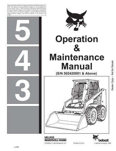
• Know where fire extinguishers and first aid kits are located and how to use them. A fire extinguisher is available from your Bobcat dealer. The fire extinguisher can be installed in the location shown [A]
MACHINE SIGNS (DECALS)
Follow the instructions on all the Machine Signs(Decals) that are on the loader. Replace any damaged machine signs and be sure they are in the correct locations. Machine signs are available from your Bobcat dealer.
MACHINE SIGNS (DECALS) (Cont’d)
Follow the instructions on all the Machine Signs (Decals) that are on the loader. Replace any damaged machine signs and be sure they are in the correct locations. Machine signs are available from your Bobcat dealer.
Instrument Panel
The instrument panel has the following instruments [A]
1.LIGHT SWITCH (OPT.) – Controls the work and travel lights.
2.IGNITION SWITCH – For starting, stopping and ‘‘pre–heating’’ the engine.
3.FUSE (ACCESSORIES) – To protect the electrical system from overload.
4.FUSE (IGNITION) – To protect the electrical system from overload.
5.HOURMETER – Records the total operating hours of the loader.
6.FUEL GAUGE – Shows the amount of fuel in the fuel tank.
7.ENGINE TEMPERATURE GAUGE – Shows the engine coolant temperature.
8.ENGINE WARNING LIGHT – Engine oil pressure is low. Stop the engine if the light comes ‘‘ON’’.
9.TRANSMISSION WARNING LIGHT – Low transmission charge pressure, hydraulic filter needs replacement or high fluid temperature. Stop the engine if the light comes ‘‘ON’’.
10.VOLTMETER – Shows the condition of the battery and the rate of charge.
Engine Speed Control
The engine speed control (Item 1) is at the right side of the operator’s seat. Engine speed is controlled by moving the engine speed control forward to increase the engine RPM and backward to decrease the engine RPM [B]
Engine Stop Control
The engine stop control (Item 2) is located near the engine speedcontrol. Pull up on the engine stop control to stop the engine. Push down on the control after the engine is stopped [C]
Parking Brake
Lock the parking brake by pushing down on the top (toe) of the pedal [A].
To release the parking brake, push down on the bottom (heel) of the pedal [B].
Avoid Injury Or Death
When operating the machine:
• Keep the seat belt fastened snugly.
• The seat bar must be lowered.
• Keep your feet on the pedal controls.
W–2046–0595
The steering levers (Item 1) are on the right and left side in front of the seat [A].
For safe control of the loader always move the levers slowly and smoothly. Only a small movement is necessary to move the loader.
The steering levers control forward and reverse travel of the loader [B]
FORWARD TRAVEL : Push both levers forward.
REVERSE TRAVEL : Pull both levers backward.
NORMAL TURNING: Move one lever farther forward than the other.
FAST TURNING: Push one lever forward and pull the other lever backward.
For slow travel speed, push the levers forward only a small amount.
To increase travel speed, push the levers farther forward.
For maximum pushing force, push the levers forward only a small amount with the engine at full RPM.
Backward
Left Turn
Right Turn
Fast Turnfast Turn
Hydraulic Controls
Foot Pedals
Keep both feet on pedals while operating machine. Failure to do so can cause serious injury.
W–2002–1285
Put your feet on the pedals and KEEP THEM THEREany time you operate the loader.
Two foot pedals (Item 1) control the hydraulic cylinders for the tilt and lift function [A]
Lift Arm Operation
The left pedal controls the lift arms. Push on the bottom (heel) (Item 2) of the pedal to raise the lift arms [A]
Push on the top (toe) (Item 3) of the pedal to lower the lift arms [A]. Use the ’’Float’’ position of the lift arms to level loose material while driving backward.
The optional bucket position valve, will keep the bucket at a level position when the lift arms are being raised.
Tilt Operation (Bucket)
The right pedal controls the action of thebucket. Push the top (toe) (Item 4) of the pedal to tilt the bucket forward [A]
Push the bottom (heel) (Item 5) of the pedal to tilt the bucket backward [A]
HYDRAULIC CONTROLS (Cont’d)
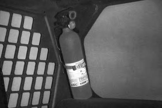
Auxiliary Hydraulics Operation (Optional)
The right steering lever is also the control lever for the front auxiliary hydraulics [A]
Move the right steering lever to the left or to the right to activate the auxiliary hydraulics and operate an attachment (Example: To open or close grapple teeth). Move the lever in the opposite direction to reverse the action of the attachment [B]
Move the steering lever all the way to the right (Item 1) to put the control valve into the ‘‘detent’’ position for a constant flow of hydraulic fluid under pressureto the quick couplers [B].
NOTE:See Page 46 to remove auxiliary control lobolt.
Daily Inspection
The loader must be in good operating condition [A].
Check the following items:
* Engine Oil
* Hydraulic/Hydrostatic Fluid
* Air Cleaner Condition Indicator
* Engine Cooling System *
* Operator Cab, Seat Belt, Seat Bar & Pedal Interlocks
* Lift Arms & Cylinder Pivot Pins
* Tires & Tire Pressure
* Any Loose or Broken Parts
* Safety Tread & Safety Signs
Follow the maintenance requirements on the Service Schedule Decal, located inside the rear door [B].
Instructions are necessary before operating or servicing machine. Read Operation & Maintenance Manual, Handbook and signs (decals) on machine. Follow warnings and instructions in the manuals when making repairs, adjustments or servicing. Check for correct function after adjustments, repairs or service. Failure to follow instructions can cause injury or death.
W–2003–0797
Seat Bar Restraint System
The seat bar restraint system has a pivoting seat bar (Item 1) with arm rests and has spring loaded interlocks for the lift and tilt control pedals. Theoperator controls the use of the seat bar. The seat bar in the down position helps to keep the operator in the seat. The interlocks require the operator to lower the seat bar in order to operate the foot pedal controls. When the seat bar is up, the lift and tilt control pedals are locked when returned to the neutral position [A]
AVOID INJURY OR DEATH
When operating the machine:
• Keep the seat belt fastened snugly.
• The seat bar must be lowered.
• Keep your feet on the pedal controls.
W–2046–0595
The spring loaded interlocks (Item 1) control the locking and unlocking functions of the control pedals [A]
The interlocks (Item 1) require the operator to lower the seat bar (Item 2) which allows the operator to move the foot pedals to control the lift and tilt functions [B]
When the seat bar is lowered, it pushes the interlock (Item 1) down on both sides, releasing the pedal linkages (Item 3) from the interlocks [B].
The pedals now pivot in both directions when the interlock is down.
AVOID INJURY OR DEATH
Before you leave the operator’s seat:
• Lower the lift arms, put the attachment flat on the ground.
• Stop the engine.
• Engage the parking brake.
• Raise seat bar, move pedals until both lock.
W–2045–1086
AVOID INJURY OR DEATH
The seat bar system must lock the lift and tilt control pedals in neutral when the seat bar is up. Service the system if pedals do not lock correctly.
W–2105–1285
When the seat bar is raised, spring forces raise the interlocks [C].
The foot pedals will not pivot when the interlock is up.
Refer to the Preventive Maintenance section for Seat Bar Restraint System Inspection & Maintenance.

Getting Ready For Operation
Read this Operation & Maintenance Manual and the Operator’s Handbook before operating the loader [A]
Operator must have instructions before running the machine. Untrained operators can cause injury or death.
W–2001–0596
Use the bucket or attachment steps, grab handles and safety tread (on top of the loader lift arm crossmember and main frame) to get on and off the loader [B]
Safety treads are installed on the Bobcatloader to provide a slip resistant surface for getting on and off the loader. Keep the safety treads clean and replace when damaged. Replacement treads are available from your dealer.
Pull the seat lever (Item 1) and adjust the seat position for comfortable operation of the loader controls [C]
Fasten the seat belt snugly and adjust it so that the buckle is centered between the hips [D].
AVOID INJURY OR DEATH
When operating the machine:
• Keep the seat belt fastened snugly.
• The seat bar must be lowered.
• Keep your feet on the pedal controls.
W–2046–0595
GETTING READY FOR OPERATION (Cont’d)
Lower the seat bar [A]
Be sure the parking brake is engaged.
All controls must be in the neutral position before you start the engine (See ‘‘Normal Starting Condition’’, Page 9).
Keep feet on the pedals while seated in the loader [B].
Starting The Engine
When an engine is running in an enclosed area, fresh air must be added to avoid concentration of exhaust fumes. If the engine is stationary, vent the exhaust outside. Exhaust fumes contain odorless, invisible gases which can kill without warning.
W–2050–1285
AVOID INJURY OR DEATH
• Engines can have hot parts and hot exhaust gas. Keep flammable material away.
• Do not use machines in atmosphere containing explosive gas.
W–2051–1086
Normal Starting Condition
Adjust the seat position for comfortable operation of the foot pedals and steering levers.
Fasten the seat belt snugly and adjust it so the buckle is centered between the hips.
STARTING THE ENGINE (Cont’d)
Lower the seat bar [A]
Put the foot pedals and steering levers in neutral (center) position (Item 1) [B].
Be sure the parking brake is engaged.
Set the engine speed control to the half speed position (Item 2) [B]
Turn the key to the ‘‘ON’’ position. The engine and transmission warning lights must be ‘‘ON’’ when the key is on and the engine is stopped (Item 3) [B].
Turn the key to the start position (Item 4) and release it when the engine starts [B].
Do not engage the starter for longer than 15 seconds at a time. Longer use can damage the starter by overheating. Cool the starter for one minute between uses.
I–2034–0284
When the engine starts, release the key and it will return to the run position (Item 5) [B]
STOP THE ENGINE IF THE WARNING LIGHTS DO NOT GO OFF.
In cold starting conditions, turn the key all the way to the left for ‘‘PRE–HEAT’’ position (Item 6) [B]. See also Cold Starting Condition, Page 11.
STARTING THE ENGINE (Cont’d) Cold Temperature Starting Condition
If the temperature is below 32F. (0C.), use the following procedure to make starting the engine easier:
1.Replace the engine oil with the correct type and viscosity for the anticipated starting temperature (See ‘‘Oil Specifications’’, Page 31).
2.Make sure the battery is at full charge.
3.Install a block or tank heater on the engine. Follow the steps under ‘‘Normal Starting Condition’’ and repeat the ’’Pre–Heating’’ procedure until the engine starts [A]
Do not use ether with glow plug (preheat) systems. Explosion can result which can cause injury or death.
Warming The Hydraulic/Hydrostatic System
Let the engine run for a minimum of 5 minutes to warm the engine and hydrostatic transmission fluid before operating the loader. If the warning light comes ‘‘ON’’ when operating the loader (cold), more warm up time is needed.
Stopping The Engine
Pull the engine speed control fully backward to decrease the engine RPM.
Turn the key switch to the ‘‘OFF’’ position.
Pull up on the engine stop control to stop the engine. Push down on the engine stop control after the engine has stopped.