12 minute read
MAINTENANCE SAFETY


Instructions are necessary before operating or servicing machine. Read and understand the Operation & Maintenance Manual, Handbook and signs (decals) on machine. Follow warnings and instructions in the manuals when making repairs, adjustments or servicing. Check for correct function after adjustments, repairs or service. Untrained operators and failure to follow instructions can cause injury or death.
W–2003–0199
Safety Alert Symbol:This symbol with a warning statement, means: “Warning, be alert! Your safety is involved!” Carefully read the message that follows.
Correct Correct Correct
Never service the Bobcat® Skid Steer Loader without instructions.
Use the correct procedure to lift or lower operator cab.
Cleaning and maintenance are required daily.
Wrong Wrong Wrong
Have good ventilation when welding or grinding painted parts. Wear dust mask when grinding painted parts. Toxic dust and gas can be produced.
Avoid exhaust fume leaks which can kill without warning. Exhaust system must be tightly sealed.
Disconnecting or loosening any hydraulic tubeline, hose, fitting, component or a part failure can cause lift arms to drop. Do not go under lift arms when raised unless supported by an approved lift arm support device. Replace if damaged.
Never work on loader with lift arms up unless lift arms are held by an approved lift arm support device. Replace if damaged. Never modify equipment or add attachments not approved by Bobcat Company.
Wrong Wrong Wrong
Stop, cool and clean engine of flammable materials before checking fluids.
Never service or adjust loader with the engine running unless instructed to do so in the manual. Avoid contact with leaking hydraulic fluid or diesel fuel under pressure. It can penetrate the skin or eyes.
Never fill fuel tank with engine running, while smoking or when near open flame.
Keep body, jewelry and clothing away from moving parts, electrical contacts, hot parts and exhaust.
Wear eye protection to guard from battery acid, compressed springs, fluids under pressure and flying debris when engines are running or tools are used. Use eye protection approved for type of welding.
Keep rear door closed except for service. Close and latch door before operating the loader.
Lead–acid batteries produce flammable and explosive gases. Keep arcs, sparks, flames and lighted tobacco away from batteries. Batteries contain acid which burns eyes or skin on contact. Wear protective clothing. If acid contacts body, flush well with water. For eye contact flush well and get immediate medical attention.
Maintenance procedures which are given in the Operation & Maintenance Manual can be performed by the owner/operator without any specific technical training. Maintenance procedures which are not in the Operation & Maintenance Manual must be performed ONLY BY QUALIFIED BOBCAT SERVICE PERSONNEL. Always use genuine Bobcat replacement parts. The Service Safety Training Course is available from your Bobcat dealer.
Service Schedule
Maintenance work must be done at regular intervals. Failure to do so will result in excessive wear and early failures. The service schedule is a guide for correct maintenance of the Bobcat loader.
Instructions are necessary before operating or servicing machine. Read Operation Maintenance Manual, Handbook and signs (decals) on machine. Follow warnings and instructions in the manual when making repairs, adjustments or servicing. Check for correct function after adjustments, repairs or service. Failure to follow instructions can cause injury or death.
Engine Oil Check the oil level & add oil as needed.
Engine Air Cleaner Empty the dust cup and replace the filter element as needed.
Engine Cooling SystemClean debris from shrouds & grills. Check coolant level in the recovery tank and add as needed.
Tires Check for damaged tires and correct air pressure.
Seat Belt and Seat BarCheck the condition of seat belt. Check the seat bar & pedal locks for correct operation.
Safety Signs & Check for damaged signs (decals) & safety treads. Replace Safety Tread as needed
Indicator & Lights Check for correct operation of all indicators & lights.
Operator Cab Check the fastening bolts, washers and nuts. Check the condition of the cab.
Lift Arm & Bob–Tach Add grease to the fittings until extra grease shows.
Pivot Pins
Engine Oil and Filter Replace oil & filter.
Battery Check cables & water level
Hydraulic Fluid, TubelinesCheck the fluid level & add as needed. Check for damage, and Hoses leaks & replace as needed.
Control Pedals & SteeringCheck for correct operation. Make repairs or adjustments as needed.
Wheel Nuts Check for loose wheel nuts & tighten as necessary.
Parking Brake Check operation. Adjust as needed.
Alternator Belt Check tension & adjust as needed.
Spark Arrestor MufflerClean the spark chamber.
Governor Oil Level Check level, if low, add oil.
Seat Bar Grease pivots as needed.
Steering Shaft Pivots Grease two fittings. Add oil to steering shaft.
Hydraulic/Hydrostatic FilterReplace the filter element.
U–Joint Grease three (3) fittings with correct grease.
Final Drive Trans. (Chaincase)Check fluid level & add as needed.
Engine Ignition SystemCheck the timing. Replace the spark plugs.
Fuel Filter Replace the filter element.
Hyd./Hydro. ReservoirReplace the reservoir breather cap.
Chaincase Replace the fluid.
Hyd. Reservoir Replace the fluid.
Check wheel nut torque every 8 hours for the first 24 hours. Also replace hydraulic/hydrostatic filter element when the transmission warning light comes ON. Or every 12 months.
NOTE:Lift arm stops are available from your Bobcat dealer.
Never work on a machine with the lift arms up unless the lift arms are secured by a lift arm support device. Failure to use an approved lift arm support device can allow the lift arms or attachment to fall and cause injury or death.
Maintenance and service work can be done with the lift arms lowered.
Place jackstands under the rear corners of the loader.
One person must be in the operator’s seat, with the seat belt fastened and the seat bar lowered, until the lift arm support device is installed.
Start the engine and raise the lift arms all the way up. Have a second person install the lift arm support device over the rod of one of the lift cylinders [A].
The lift arm stop must be tight against the cylinder rod. Lower the lift arms until the stop is held between the lift arm and the lift cylinder.
Both sets of fasteners at the front of the operator cab (ROPS) must be assembled as shown in this manual. Failure to secure ROPS correctly can cause injury or death.
Operator Cab
The Bobcat loader has an operator cab (ROPS and FOPS) as standard equipment to protect the operator from rollover and falling objects. Check with your dealer if the operator cab has been damaged.
Plate
Vibration Dampner
Washer
Never modify operator cab by welding, grinding, drilling holes or adding attachments unless instructed to do so by Melroe Company. Changes to the cab can cause loss of operator protection from rollover and falling objects, and result in injury or death.
W–2069–1285
The operator cab fastening bolts and nuts must be tight to 40–50 ft.–lbs. (54–68 Nm) torque [B].
OPERATOR CAB (Cont’d)
Raising the Operator Cab (Cont’d)
Stop the loader on a level surface. Put the lift arms all the way down.
If the lift arms must be up while raising the operator ca, install a lift arm stop (Page 20).
Before the cab or the lift arms are raised for service, jackstands must be put under the rear corners of the frame. Failure to use jackstands can allow the machine to tip backward causing injury or death.
Remove the two fasteners (including the washer) at the front corners of the operator cab [A]
If the lift arms are down, or are held up by a lift arm stop, stand in front of the loader. Lift on the grab handle and bottom of the operator cab slowly until the operator cab is all the way up [B] & [C]
Cylinders for raising and lowering operator cab have gas under pressure. Do not open cylinder. Only qualified service personnel can remove the cylinder.
Lowering the Operator Cab
If the lift arms are down, or are held up by a lift arm stop, stand in front of the loader. Pull down on the bottom of the operator cab and use the grab handle until the cab is all the way down [B] & [C]
Install the two fasteners and washers. Tighten the nuts to 40–50 ft.–lbs. (54–69 Nm) torque [A]
Seat Bar System
The seat bar system has a pivoting seat bar with arm rests and has spring loaded interlocks for the lift and tilt control pedals. The operator controls the use of the seat bar. The seat bar in the down position helps to keep the operator in the seat. The interlocks require the operator to lower the seat bar in order to operate the foot pedal controls. When the seat bar is up, the lift and tilt control pedals are locked when returned to the neutral position
Avoid Injury Or Death
The seat bar system must lock the lift and tilt control pedals in neutral when the seat bar is up. Service the system if pedals do not lock correctly.
W–2105–1285
Seat Bar Inspection
Sit in the seat and fasten the seat belt. Engage the parking brake. Pull the seat bar all the way down. Start the engine. Operate each foot pedal to check both the lift and tilt functions. Raise the lift arms until the bucket is about 2 feet (600 mm) off the ground.
Raise the seat bar. Try to move each foot pedal. Pedals must be firmly locked in neutral position. There must be no motion of the lift arms or tilt (bucket) when the pedals are pushed.
Pull the seat bar down, lower the lift arms and place the bucket flat on the ground. Stop the engine. Raise the seat bar and operate the foot pedals to be sure that the pedals are firmly locked in the neutral position. Unbuckle the seat belt.
Seat Bar Maintenance
Clean any debris or dirt from the moving parts [A] & [B]
Inspect the linkage bolts and nuts for tightness. The correct torque is 25–28 ft.–lbs. (34–38 Nm).
Use general purpose grease to lubricate the seat bar pivot points at each side of the cab [A]
If the seat bar system does not function correctly, check for free movement of each linkage part. Check for excessive wear. Adjust pedal control linkages. Replace parts that are worn or damaged. Use only genuine Melroe replacement parts.
Rear Door
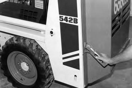
Opening the Rear Door
Avoid Injury
Never service or adjust the machine when the engine is running unless instructed to do so in the manual.
Open the rear door to service the engine. Pull the door latch up and to the left to release the door latch [A]
The door can then be opened to get to the engine compartment.
Keep the rear door closed when operating the machine. Failure to do so could seriously injure a bystander.
Adjusting the Rear Door

Loosen the set screw (Item 1) [B]
Loosen the nut (Item 2) [B]
Turn the bolt (Item 3) [B] in or out, until the door contacts both the top and bottom of the loader frame (Item 1) [C] with the lever in the latched position.
NOTE: It takes approximately 50 lbs. (22 kg) of force to push the lever down when the latch is adjusted correctly.
With the set screw up, the flanges at the bolts (Item 2) [C] must be to the sides so that the set screw aligns with the flat surface of the end of the bolt.
Tighten the set screw. Tighten the nut to 65–70 ft.–lbs. (88–95 Nm) torque.
Air Cleaner Service
See the Service Schedule Page 19 for the interval to service the air cleaner.
To replace the filter element, use the following procedure:
Remove the dust cap [A]
Remove the filter element wing nut [B]
Remove the filter element [C].
Check the air cleaner housing for holes from corrosion. Install the new filter element. Install and tighten the wing nut.
Check that all the air cleaner
Fuel System
Fuel Specifications
Use leaded or unleaded gasoline in the engine.
Filling the Fuel Tank
Stop and cool the engine before adding fuel. NO SMOKING! Failure to obey warnings can cause an explosion or fire.
W–2063–0887
Filling the Fuel Tank
Remove the filler cap (Item 1) [A]

Use a clean, approved safety container to add fuel to the tank
The key switch must be in the ‘‘OFF’’ position and the engine cool.
Add fuel only in an area that has free movement of air and no open flames or sparks. NO SMOKING! [B]
After the fuel has been added install the filler cap and.
Always clean up spilled fuel or oil. Keep heat, flames, sparks or lighted tobacco away from fuel and oil. Failure to use care around combustibles can cause explosion or fire which can result in injury or death.
W–2103–1285
See the Service Schedule (Page 19) for the interval to service the fuel filter.
Close the fuel shut–off valve (Item 1) [C]
Loosen the hose clamps and remove the filter (Item 1) [D]
Install the new fuel filter element and tighten the hose clamps.
Open the fuel shut–off valve.

Engine Lubrication System
Check the engine oil level every day.
Stop the engine. Open the rear door and remove the dipstick [A]
Keep the oil level between the marks on the dipstick. Use a good quality motor oil that meets API Service Classification of SE or SF (See the Oil Chart below).
RECOMMENDED SAE VISCOSITY NUMBER (LUBRICATION OILS FOR ENGINE CRANKCASE)
TEMPERATURE RANGE ANTICIPATED BEFORE NEXT OIL CHANGE (GASOLINE: USE API CLASSIFICATION SE or SF)
Replacement of Engine Oil and Filter
See the Service Schedule (Page 19) for the service interval for replacing the engine oil.
1.Run the engine until it is at operating temperature. Stop the engine.
2.Open the rear door.
3.Remove the drain plug and drain the oil into a container [B]
4.Remove the oil filter [C]
5.Clean the filter housing surface. Put clean oil on the new oil filter gasket. Install the filter and hand tighten only.
6.Install and tighten the oil plug. Remove the filler cap. Add the correct amount of oil to the engine (See Specification, Page 50) [D].
7.Start the engine and let it run for several minutes. Stop the engine. Check for leaks and check the oil level. Add oil as needed if it is not at the top mark on the dipstick.

Always clean up spilled fuel or oil. Keep heat, flames, sparks or lighted tobacco away from fuel and oil. Failure to use care around combustibles can cause explosion or fire which can result in injury or death.
W–2103–1285
Cooling System
Keep the rear grill area free from debris or overheating will result [A]
Wear safety glasses to prevent eye injury when any of the following conditions exist:
• When fluids are under pressure.
• Flying debris or loose material is present.
• Engine is running.
• Tools are being used.
Rear Grill
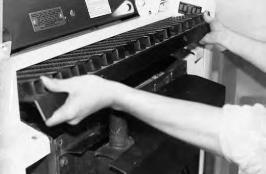
To remove the rear grill from the loader, use the following procedure: Remove the four bolts from the rear grill [B] & [C]


COOLING SYSTEM (Cont’d)
Coolant Level
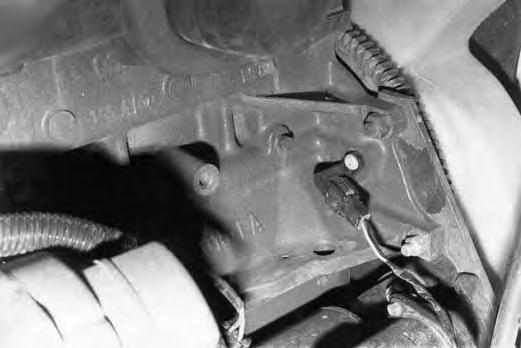
The coolant recovery tank is located in the engine compartment at the left side [A]
When the engine is cool, the coolant recovery tank must be 1/3 full.
When coolant level is low, add pre–mixed 50% ethylene glycol and 50% water to the recovery tank [B]
Removing Coolant from the Cooling System
Do not remove radiator cap when the engine is hot. You can be seriously burned.
W–2070–1285
1.Open the rear door. Remove the rear gill (Page 27).
2.Remove the radiator cap [C]
3.Remove the drain plug (Item 1) from the engine block [D]
4.After all the coolant is removed, install and tighten the plug.
5.Mix the coolant in a separate container (See Specifications, Page 50 for correct capacity).
NOTE:Protect the cooling system by adding pre–mixed 50% ethylene glycol and 50% water to the system. This mixture will protect the cooling system to –34°F (–36°C).
6.Fill the radiator with the pre–mixed coolant. Install the radiator cap. Install the rear grill.

7.Fill the coolant recovery tank 1/3 full.
8.Run the engine until it is at operating temperature. Stop the engine. Check the coolant level in the recovery tank and add coolant as needed.
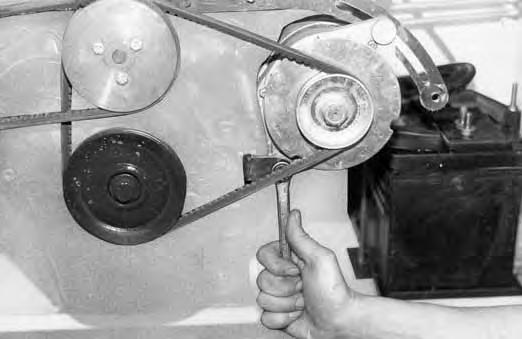
Governor
See your Bobcat dealer or Service Manual for the complete and correct procedure for governor adjustment.
Belt Adjustment
Loosen the two mounting bolts (Item 1) [A]
Move the governor until the belt tension is 1/4” (6,4 mm) movement at the middle of the belt span with 20 lbs. (89 N) of force [B]
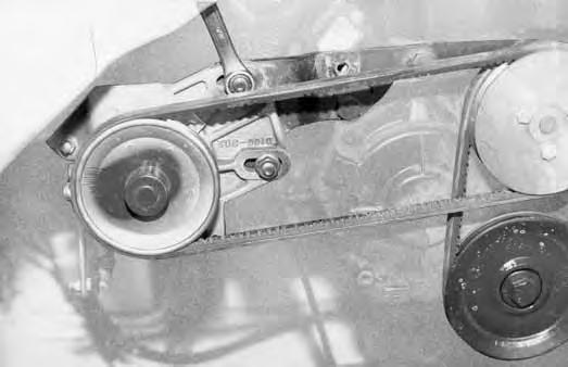
Tighten the mounting bolts.
Governor Oil Level
See the Service Schedule (Page 19) for the correct interval when to check the governor oil level. Use the following procedure:
1.Stop the engine. Open the rear door.
2.Remove the check plug (Item 1) [C]. If oil flows from the hole, the oil level is correct.
3.If no oil flows, remove the fill plug (Item 2) at the back of the governor housing [C].
4.Add SAE 10W/30 or 10W/40 oil until it flows from the check plug hole. Install and tighten the plugs.
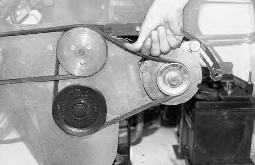
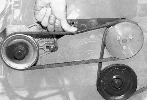
Alternator Belt
Adjusting the Alternator Belt
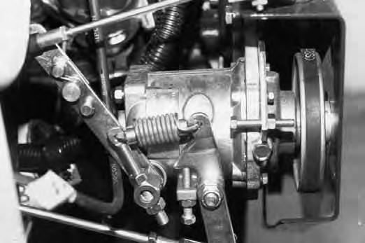
Loosen the alternator mounting bolt [A].
Loosen the adjusting bolt [B].
Move the alternator until the belt has 3/8” (9,5 mm) movement at the middle of the belt span with 22 lbs. (98 N) of force [C]

Tighten the adjusting bolt and mounting bolt.