10 minute read
MAINTENANCE SAFETY


Instructions are necessary before operating or servicing machine. Read Operation & Maintenance Manual, Handbook and signs (decals) on machine. Follow warnings and instructions in the manuals when making repairs, adjustments or servicing. Check for correct function after adjustments, repairs or service. Failure to follow instructions can cause injury or death.
W–2003–0797
Safety Alert Symbol:This symbol is used for important safety messages. When you see this symbol, follow the safety message to avoid personal injury or death.
Correct
Correct
Correct
Never service the Bobcat® Skid Steer Loader without instructions.
Use the correct procedure to lift or lower operator cab with lift arms down.
Cleaning and maintenance are required daily.
Have good ventilation when welding or grinding painted parts. Wear dust mask when grinding painted parts. Toxic dust and gas can be produced.
Vent exhaust to outside when engine must be run for service. Avoid exhaust fume leaks which can kill without warning. Exhaust system must be tightly sealed.
Never work on loader with lift arms up unless lift arms are held by a lift arm support device. Never modify equipment or add attachments not approved by Melroe Company.
Wrong Wrong Wrong
Stop, cool and clean engine of flammable materials before checking fluids.
Never service or adjust loader with the engine running unless instructed to do so in the manual. Avoid contact with leaking hydraulic fluid or diesel fuel under pressure. It can penetrate the skin or eyes.
Never fill fuel tank with engine running, while smoking or when near open flame.
Keep body, jewelry and clothing away from moving parts, electrical contacts, hot parts and exhaust. Wear eye protection to guard from battery acid, compressed springs, fluids under pressure and flying debris when engines are running or tools are used. Use eye protection approved for type of welding. Keep rear door closed except for service. Close and latch door before operating the loader.
Lead–acid batteries produce flammable and explosive gases. Keep arcs, sparks, flames and lighted tobacco away from batteries. Batteries contain acid which burns eyes or skin on contact. Wear protective clothing. If acid contacts body, flush well with water. For eye contact flush well and get immediate medical attention.
Maintenance procedures which are given in the Operation & Maintenance Manual can be performed by the owner/operator without any specific technical training. Maintenance procedures which arenot in this manual must be performed ONLY BY QUALIFIED BOBCAT SERVICE PERSONNEL. Always use genuine Bobcat replacement parts.
Service Schedule
Maintenance work must be done at regular intervals. Failure to do so will result in excessivewear and early failures. The service schedule is a guide for correct maintenance of the Bobcat loader.
Instructions are necessary before operating or servicing machine. Read Operation Maintenance Manual, Handbook and signs (decals) on machine. Follow warnings and instructions in the manual when making repairs, adjustments or servicing. Check for correct function after adjustments, repairs or service. Failure to follow instructions can cause injury or death.
Engine Oil Change engine oil (New Engine Only).
Engine Oil Check level and add oil needed.
Engine Cooling SystemCheck and clean as needed.
Tires Check air pressure and for damage to the tires.
Seat Belt, Seat Bar & Check the condition of seat belt. Check the seat Pedal Interlocks. bar for correct operation to lock both foot pedals.
Safety Signs (Decals) Check for damaged signs (decals) and safety. & Safety Treads. treads Replace any signs (decals) and safety treads that are damaged.
All Loader Pivot PointsAdd grease to the fittings until the extra grease shows.
Hydraulic Fluid Check the fluid level in the reservoir & add fluid as needed.
Engine Oil Replace oil.
Engine Oil Replace oil (S/N 25000 & Above)
Engine Air Cleaner Clean or replace filter element as needed.
Battery Check water level and add as needed. Clean the cables.
Control Pedals & SteeringCheck operation. Make repairs & adjustments as needed
Wheel Nuts Check for loose wheel nuts and tighten to 40–45 ft.–lbs.(54–61 Nm) torque.
Parking Brake Check operation. Make adjustments as needed.
Final Drive TransmissionCheck fluid level.
(Chaincase)
Engine Oil Filter Replace the filter (S/N 25000 & Above)
Hydraulic Filter ElementReplace filter element.
Spark Arrestor MufflerClean the spark chamber.
Steering Levers Lubricate the grease fittings and the oil hole in the steering shaft.
Engine Ignition SystemReplace the spark plugs.
Engine Air ShroudingRemove and clean shrouding and cooling fins.
Engine Fuel Filter Replace the filter element.
Hydraulic Reservoir Fill Replace the breather cap. Cap (Breather)
Final Drive TransmissionReplace the fluid. (Chaincase)
Hydraulic/HydrostaticReplace the fluid. Reservoir
Both sets of fasteners at the front of the operator cab (ROPS) must be assembled as shown in this manual. Failure to secure ROPS correctly can cause injury or death.
W–2005–1189
NOTE:Lift arm support device are available from your Bobcat loader dealer.
Never work on a machine with the lift arms up unless the lift arms are secured by a lift arm support device. Failure to use an approved lift arm support device can allow the lift arms or attachment to fall and cause injury or death.
W–2059–0991
Maintenance and service work can be done with the lift arms lowered.
Place jackstands under the corners of the loader.
One person must be in the operator’s seat, with the seat belt fastened and the seat bar lowered, until the lift arm support device is installed [A].
Start the engine and raise the lift arms all the way up. Have a second person install the lift arm support device over the rod of one of the lift cylinders.
The lift arm support device must be tight against the cylinder rod. Lower the lift arms until the support device is held between the lift arm and the lift cylinder.
OPERATOR CAB (ROPS & FOPS)
The Bobcat loader has an operator cab as standard equipment to protect the operator from roll over (ROPS) and falling objects (FOPS).
Check with your dealer if the operator cab has been damaged.
Never modify operator cab by welding, grinding, drilling holes or adding attachments unless instructed to do so by Melroe Company. Changes to the cab can cause loss of operator protection from rollover and falling objects, and result in injury or death.
W–2069–1285
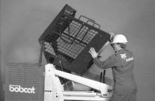
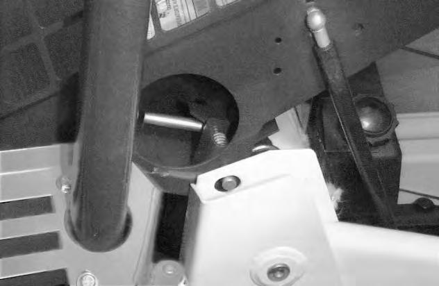
The operator cab fastening bolts and nuts must be tight [B] & [C]
Tighten to 40–50 ft.–lbs. (54–68 Nm) torque.
OPERATOR CAB (ROPS & FOPS) (Cont’d)
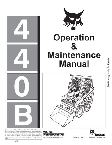
Raising the Operator Cab
Stop the loader on a level surface. Put the lift arms all the way down.
If the lift arms must be up while raising the cab, install a lift arm support device. (See Page 20.)
Before the cab or the lift arms are raised for service, jackstands must be put under the rear corners of the frame. Failure to use jackstands may allow the machine to tip backward causing injury or death.
Remove the two fasteners at the front corners of the operator cab. (See [B] or [C], Page 20.)
With Gas Cylinder: Standing on the ground one person lift slowly until operator cab is all the way up [A]
Without Gas Cylinder: Two persons are needed to raise the operator cab. Stand on the ground (one person on each side) and lift slowly until the operator cab is all the way up.
The operator cab will lock in the raised position.
Lowering the Operator Cab
Move the locking mechanism by pushing the lever inward from the locked position [B] and turning the lever until it stays in the unlocked position [C]
REMOVE YOUR HAND BEFORE LOWERING THE OPERATOR CAB.
The cab must be held to prevent falling while hand is in access hole.
With Gas Cylinder: Stand on the ground and pull down on the operator cab.
Without Gas Cylinder: Two persons are needed to lower the operator cab (one person on each side). Slowly lower the cab by holding the bottom of the cab and the grab handles.
Avoid slippery surfaces when lowering the cab.
NOTE:Guide the operator cab over the fastening bolts to prevent thread damage.
Install the two fasteners (including the washers or plates) and tighten the nuts. (See [B] or [C] Page 20.)
OPERATOR CAB (Cont’d)
Seat Bar System
The seat bar system has a pivoting seat barwith arm rests and has spring loaded interlocks for the lift and tilt control pedals. The operator controls the use of the seat bar. The seat bar in the down position helps to keep the operator in the seat and unlocks the foot pedals. When the seat bar is up, the lift and tilt pedals are locked in neutral position.
Seat Bar Inspection
Sit in the seat and fasten seat belt snugly. Engage the brake.
Pull the seat bar all the way down and start the engine.
Operate each foot pedal to check both the liftarm and tilt functions. Raise the lift arms until the bucket is about two feet (600 mm) off the ground.
Raise the seat bar. Try to move each foot pedal. Pedals must be firmly locked in the neutral position. There must be no motion of the lift arms or tilt (bucket) when the pedals are pushed.
Pull the seat bar down, lower the lift arms fully and place the bucket flat on the ground.
Stop the engine. Engage the brake. Raise the seat bar and operate the foot pedals to besure that the pedals are firmly locked in the neutral position. Unfasten the seat belt.
Seat Bar Maintenance
Clean the debris or dirt from moving parts [B] and [C]
Inspect the linkage bolts and nuts for tightness of 25–28 ft.–lbs. (34–38 Nm) torque.
Use general purpose grease to lubricate the seat barpivot points at each side of the cab [B].
If seat bar system does not function correctly, check for free movement of each linkage part. Check forexcessive wear. Adjust pedal control linkages. Replace parts that are worn, or damaged. Use only genuine Melroe replacement parts.
Avoid Injury Or Death
The seat bar system must lock the lift and tilt control pedals in neutral when the seat bar is up. Service the system if pedals do not lock correctly.
W–2105–1285
Avoid Injury
Never service or adjust the machine when the engine is running unless instructed to do so in the manual.
Keep
Air Cleaner System
See the Service Schedule Page 19 for the interval to service the air cleaner system.
To replace or service the air cleaner element, use the following procedure:
1.Loosen the wing nuts [B]
2.Remove the dust cover.
3.Remove
.
Fuel System
Use 87 octane regular gasoline or unleaded gasoline in the Kohler engine.
Gasohol (up to 10% ethyyl alcohol, 90% unleaded gasoline by volume) fuel for the Kohler engine.
Stop and cool the engine before adding fuel. NO SMOKING! Failure to obey warnings can cause an explosion or fire.
Filling the Fuel System
Remove the fuel fill cap [A].
Use a clean, approved safety container to add fuel.
The key switch must be in the OFF position and the engine cool.
Add fuel only in an area that has a free movement of air and no open flames or sparks. NO SMOKING! [B]
After the fuel tank is full, install the fill cap and tighten.
Fuel Filter
See the Service Schedule Page 19 for the interval to service the fuel filter.
Remove the fuel filter, replace with a newfilter, make sure all the connections are tight [C]
Engine Lubrication System
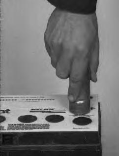
Check the oil level every day [A]
Stop the engine and remove the dipstick[A]. Keep the oil level between the ADD and FULL marks on the dipstick. Use a good quality motor oil that has the correct API Service Classification. (See the Chart.)
Straight 30 weight oil is preferred. If multiviscosity oil is used, be aware of resulting increase in oil consumption and in combustion deposits when used in temperatures above 32°F (0°C).
Using oil other than SF–quality, or oil change intervals longer than recommended could reduce engine life. Damage to engine due to improper maintenance or use of incorrect oil quality and/or viscosity is not covered by the engine warranty.
Engine Oil Replacement
See the Service Schedule Page 19 for the service interval for replacing the engine oil and filter.
Use the following procedure to replace the engine oil and filter:
Operate the engine until it is at operating temperature. Stop the engine.
Open the rear door.
Remove the drain plug [B]. Drain oil into a container.
After all the oil is removed from the engine, install theplug and tighten.
Remove the oil filter (Item 1)[D] at the suggested interval. Clean the filter contact surface on the engine.
Put clean oil on the gasket of the new filter. Install filter and tighten hand tight.
Remove the fill cap [C]. Add the correct amount of oil. (See Specifications, Page 49.) (See the Chart for the correct oil.)
Install the oil fill cap.
Start the engine and let it run for several minutes. Stop the engine. Check the oil level. Add oil as needed if it is not at the top mark on the dipstick.
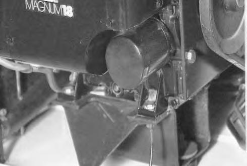
Engine Cooling System
The loader uprights and the engine cooling fins must be kept clean and free of debris or overheating will result.
Wear safety glasses to prevent eye injury when any of the following conditions exist:
• When fluids are under pressure.
• Flying debris or loose material is present.
• Engine is running.
• Tools are being used.
W–2019–1285
Use air pressure or water spray to clean the vent openings in the loader uprights.
Remove the shrouding on the engine to check the cooling fins [A]
If hard deposits are found on the cooling fins [B], the loader must be taken to the dealer to service the cooling fins at the front of the engine.
Replace all the covers and shrouding after cleaning the cooling system.
Never run the engine with any of the covers or air ducts removed. Overheating can damage the engine and hydraulic/hydrostatic system.
I–2020–1285
Check the condition of the rubber seal in the rear door. The rubber seal must be in good condition to prevent overheating of the engine.
Electrical System
The loader has a 12 volt, negative ground flywheel alternator charging system. The alternator is located behind the flywheel.
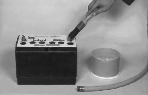
Battery Replacement
Remove the battery cables. Negative (–) cable first.
Remove the battery holddown clamp [A]
Remove the battery from the loader.
A
Clean the terminals and cable ends [B]
Install the new battery. Install the holddown clamp. Install the battery cables. Connect the negative (–) cable last to prevent sparks.
Electrical System Service
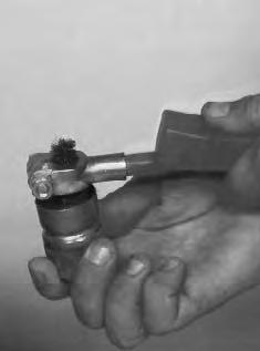
The battery cables must be clean and tight. Remove any acid or corrosion from the battery cables with baking soda and water solution [C].
Cover the terminals with Clark Battery Saver to prevent corrosion.
Check all wire connections for loose connections.
Using An Extra Battery (Jump Starting)
Keep arcs, sparks, flames and lighted tobacco away from batteries. When jumping from booster battery make final connection (negative) at engine frame.
Do not jump start or charge a frozen battery. Warm battery to 60°F. (16°C.) before connecting to a charger. Unplug charger before connecting or disconnecting cables to battery.
Battery gas can explode and cause serious injury.
W–2066–0490
If an extra battery (booster) is needed to start the engine, BE CAREFUL! One person must stay in the operator’s seat with the seat belt fastened, while another person connects and disconnects the battery cables.
Batteries contain acid which burns eyes and skin on contact. Wear goggles, protective clothing and rubber gloves to keep acid off body.
In case of acid contact, wash immediately with water for several minutes and get medical attention in case of eye contact.
W–2065–1286