1 minute read
Installing the valves


Fig. 53 Examine the valve guides (53/1) for damage and, if necessary, press them out from the combustionchamber side with the cylinder head cold.
Fig. 54 Press in new valve guides with a minimum pressure of 1000 N from the combustion-chamber side with the cylinder head cold. Caution:
After the new valve guides have been pressed in, use the hand reamer, special tool No. 74 64 1 333 532, to ream out the guides. 53
Installing the valves Fig. 55 Prior to installation, check the valves for leakage, as follows:
Fit the valves and fill fuel into the inlet and exhaust ports. If the fuel seeps through, the valve seats must be ground in with special tool No. 74 64 1 333 539. For this purpose, use grinding paste. 54
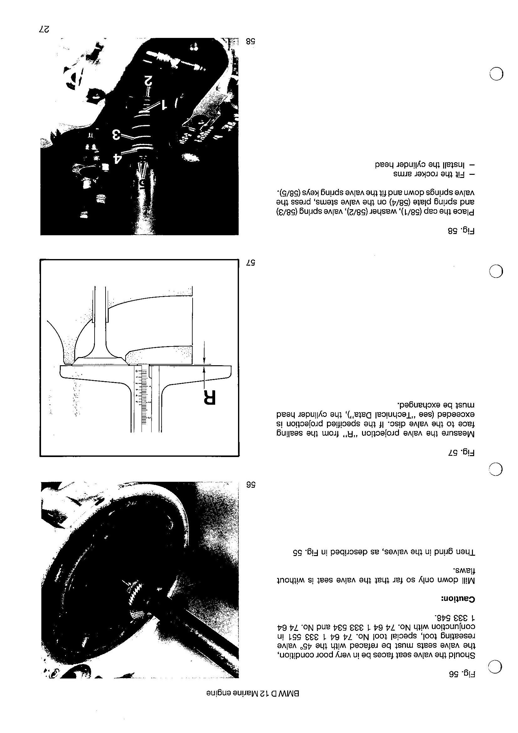
Fig. 56 Should the valve seat faces be in very poor condition, the valve seats must be refaced with the 45° valve reseating tool, special tool No. 74 64 1 333 551 in conjunction with No. 74 64 1 333 534 and No. 74 64 1 333 548.
Caution:
Mill down only so far that the valve seat is without flaws.
Then grind in the valves, as described in Fig. 55
Fig. 57 Measure the valve projection “R” from the sealing face to the valve disc. If the specified projection is exceeded (see “Technical Data”), the cylinder head must be exchanged. 56
R
Fig. 58 Place the cap (58/1), washer (58/2), valve spring (58/3) and spring plate (58/4) on the valve stems, press the valve springs down and fit the valve spring keys (58/5). — Fit the rocker arms — Install the cylinder head 57