2 minute read
Removing the LCD Module


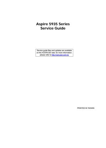
IMPORTANT: The LCD Module cannot be disassembled outside of factory conditions. If any part of the LCD Module is faulty, such as the camera, antenna or LCD panel, the whole module must be replaced. 1. See “Removing the Upper Cover” on page 63. 2. Remove the adhesive tapes securing the Antenna cables in place.
3. Pull the Antenna cables through the cover as shown. Ensure that the Antennas are completely free from the cover.
4. Disconnect the USB Board cable as shown.


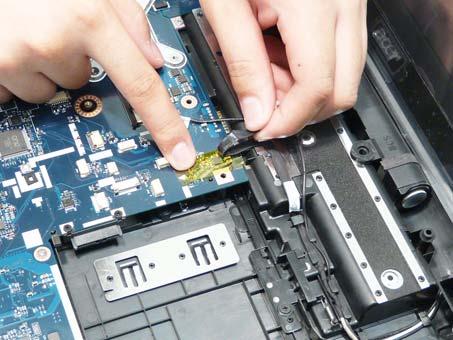
6. Remove the adhesive tapes securing the USB Board and Backlight cables in place.

7. Disconnect the Backlight and USB Board cables from the Mainboard.

9. Remove the USB Board and Backlight cables from the cable channel. Ensure that the cables are free from all cable clips.
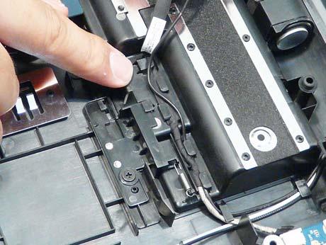

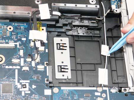
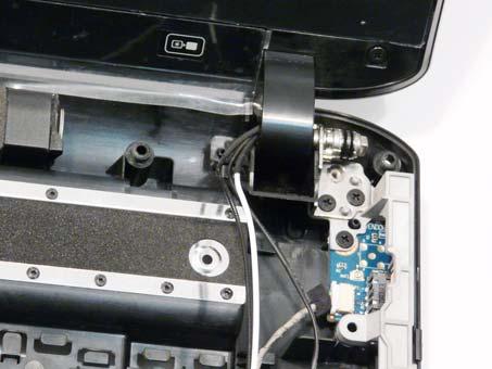
10. Remove the Antenna and Backlight cables from the cable clip as shown.
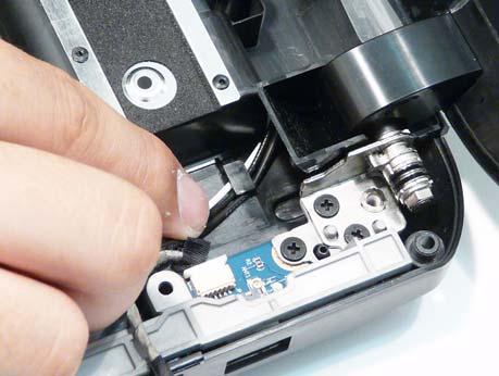


12. Remove the cables from the final cable clip as shown.


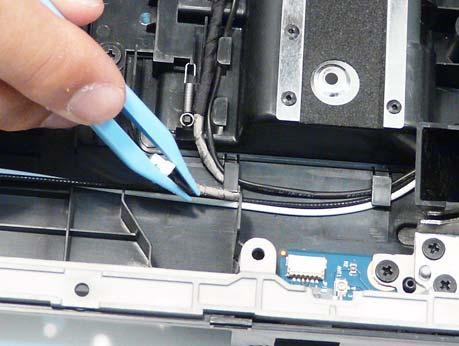
13. Disconnect the Conductive cable from the Mainboard.


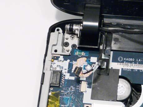
15. Remove the Conductive and LVDS cables from the cable channel. Ensure that the cables are free from all cable clips.

16. Remove the four screws (two each side) securing the LCD Module to the Lower Cover.
Step
Size
LCD Module M2.5*5 4
Quantity Screw Type
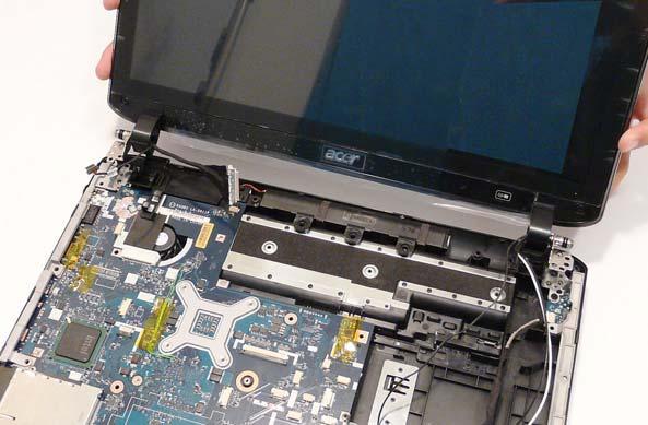
IMPORTANT: The LCD Module cannot be disassembled outside of factory conditions. If any part of the LCD Module is faulty, such as the camera, antenna or LCD panel, the whole module must be replaced.