2 minute read
Replacing the LCD Module


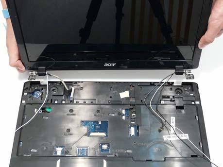
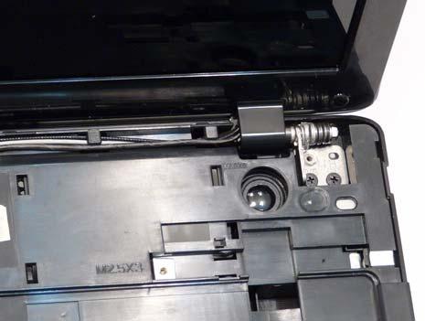
1. Align the LCD hinges with the lower case and replace the LCD module.
2. Replace the four securing screws (two each side), starting with the left side hinge.
NOTE: Two different screw sizes are used to secure the LCD module in place. The red callouts require M2.5*8 screws and the green callouts require M2.5*6 screws.
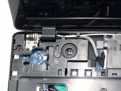
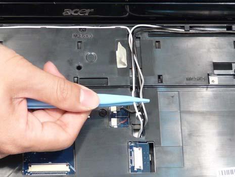
3. Run the microphone cable along the cable channel using all the available cable clips. 4. Connect the microphone cable to the Mainboard as shown.
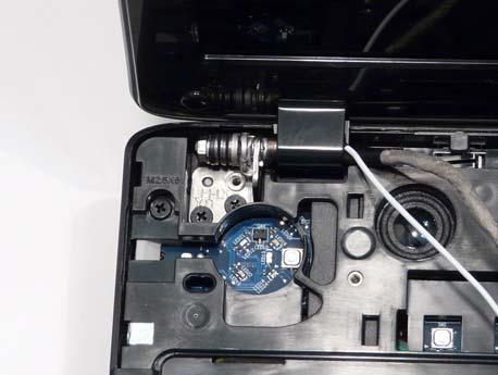
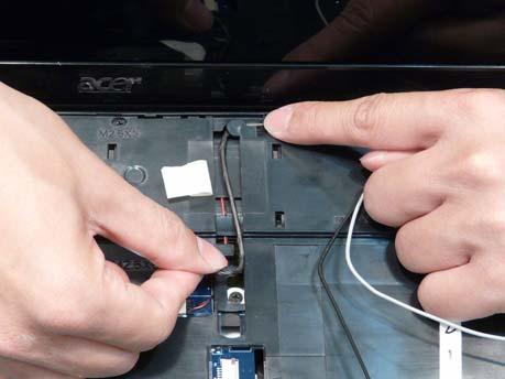
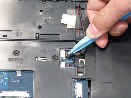
5. Run the LCD power cable along the cable channel as shown using all available cable clips. 6. Connect the power cable to the Mainboard as shown.
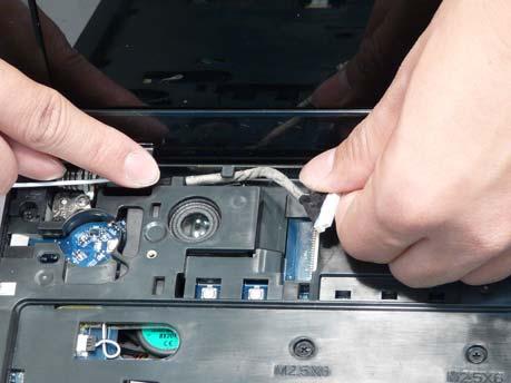
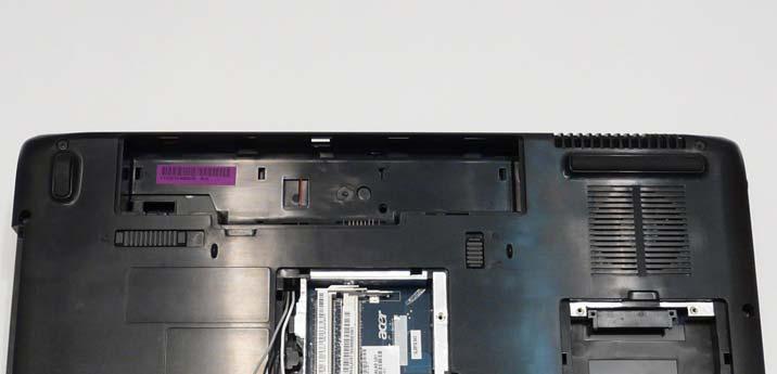
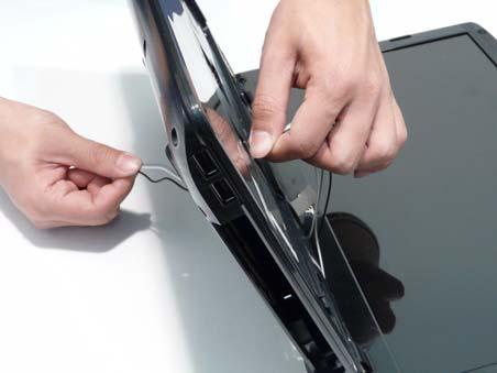
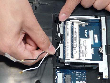
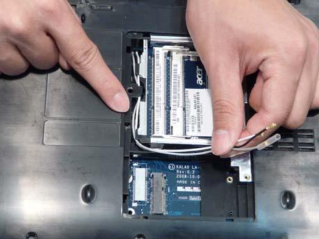
7. Push the antenna cables through the chassis and pull them all the way through from the underside.
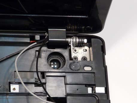
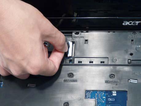
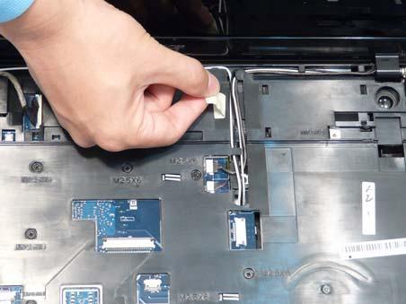
8. Run the right side cables along the cable channel as shown, using all available cable clips. 9. Run the left side cables along the cable channel as shown, using all available cable clips.
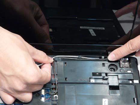
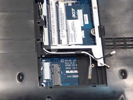
11. Place the antenna cables in the cable channel as shown using all available cable clips. 12. Replace the adhesive strip to secure the cables in place.
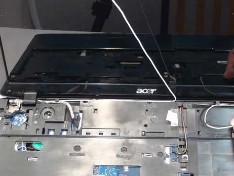
13. Turn the computer over and Run the antenna cable along the cable channel using all the available clips as shown.
15. Replace the two securing screws as shown.