2 minute read
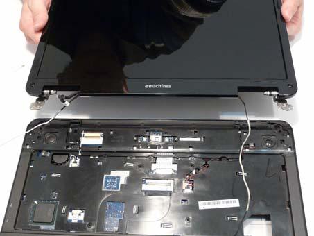
Replacing the LCD Module


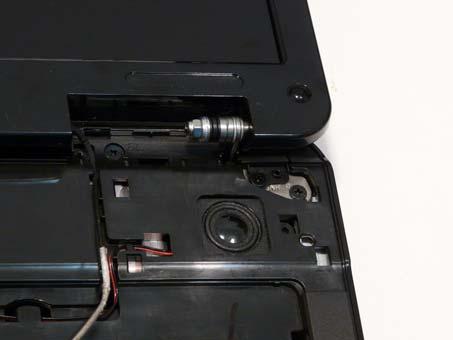
1. Align the screw holes on the LCD Module and Upper Cover and replace the LCD Module. 2. The left and right screw covers are shaped differently. Ensure that the correct cover is used.
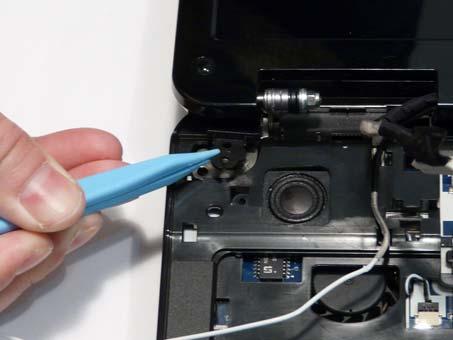
3. Replace the left screw cover as shown. Ensure that the securing tab on the rear of the cover is seated correctly in the Upper Cover.

Left Screw Cover Right Screw Cover
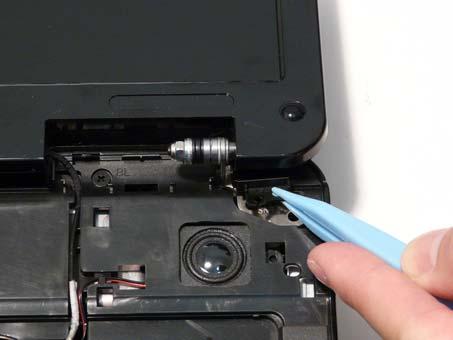
4. Replace the right screw cover as shown. Ensure that the securing tab on the rear of the cover is seated correctly in the Upper Cover.
5. Replace the four (4) screws securing the LCD Module to the Upper Cover.
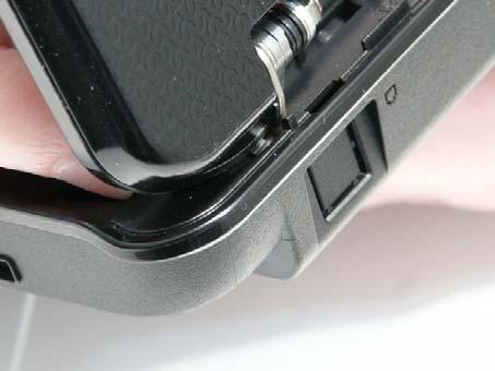
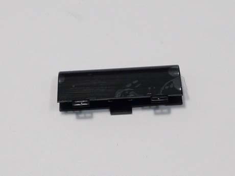
6. Ensure that the Hinge Covers are replaced correctly. Identify the rear edge of the covers by the two (2) securing clips.
Rear Securing Clips
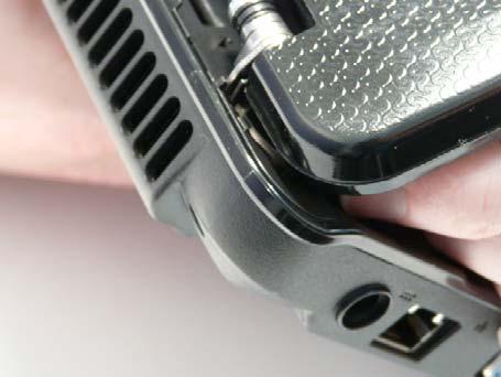
7. Align the left Hinge Cover as shown and press down to replace the cover.
8. Repeat the process for the right side Hinge Cover.
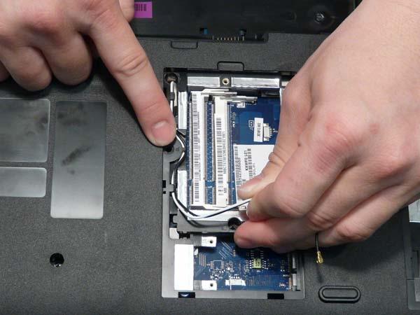
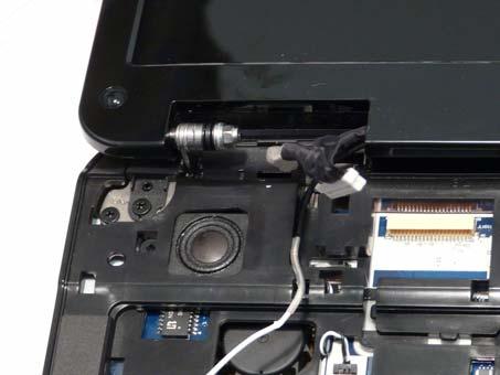
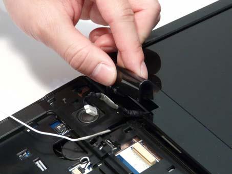
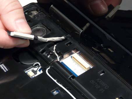
9. Run the black Antenna cable along the cable channel as shown using all available retaining clips. 10. Replace the adhesive strip to secure the cable in place.
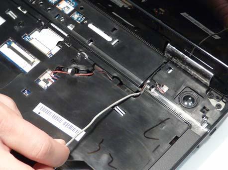
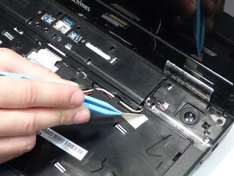
11. Run the white Antenna cable along the cable channel as shown using all available retaining clips.
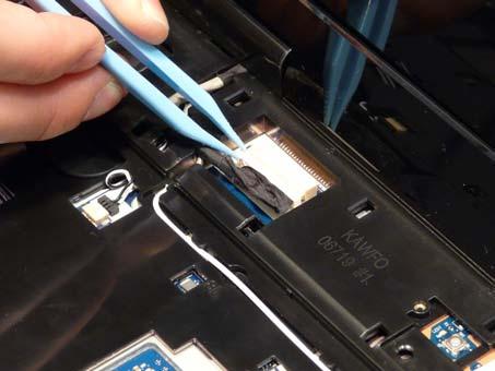
12. Run the LCD cable along the cable channel using all available cable clips. 13. Connect the LCD cable to the Mainboard as shown.
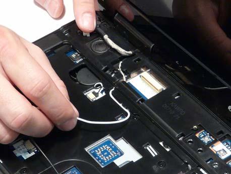
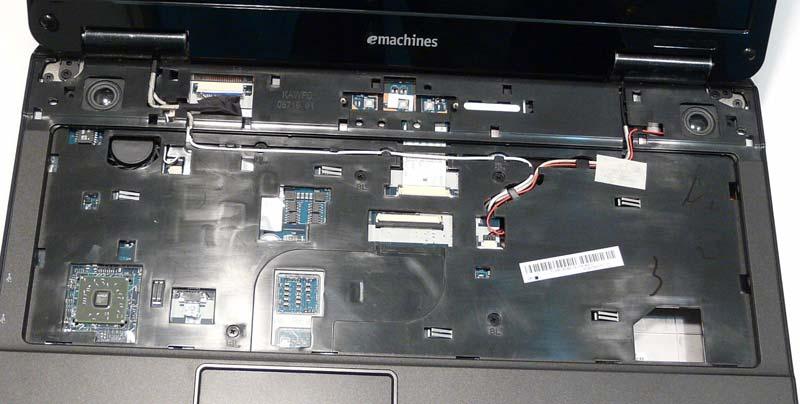
15. The Upper Cover appears as shown when the Antenna and LCD cables are correctly installed.
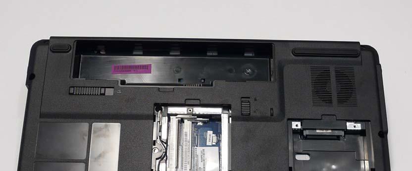
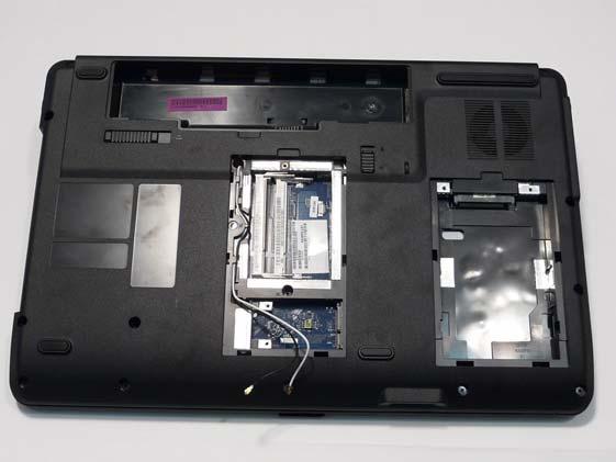
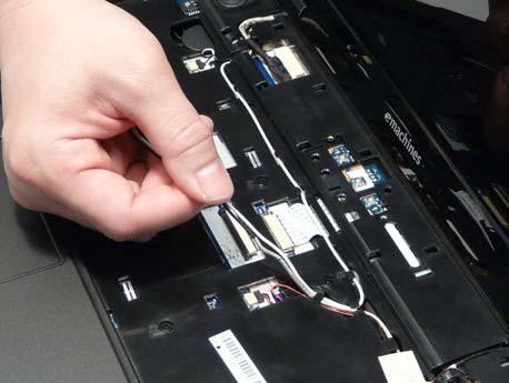
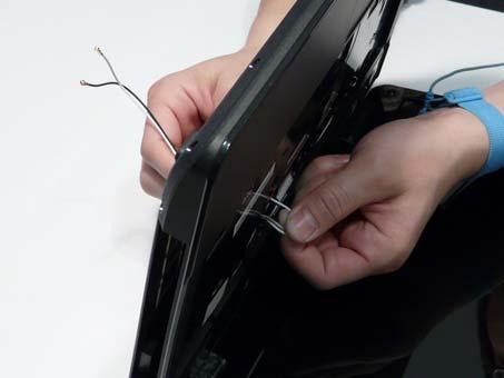
16. Turn the computer over. Run the Antenna cables along the cable channel as shown, using all available cable clips.