6 minute read
Chapter 3 Machine Disassembly and Replacement


Machine Disassembly and Replacement
This chapter contains step-by-step procedures on how to disassemble the notebook computer for maintenance and troubleshooting. To disassemble the computer, you need the following tools: ! Wrist grounding strap and conductive mat for preventing electrostatic discharge ! small Philips screwdriver ! flat head screwdriver ! Philiips screwdriver ! nut screwdriver ! tweezers NOTE: The screws for the different components vary in size. During the disassembly process, group the screws with the corresponding components to avoid mismatch when putting back the components. When you remove the stripe cover, please be careful not to scrape the cover.
Before You Begin
Before proceeding with the disassembly procedure, make sure that you do the following: 1. Turn off the power to the system and all peripherals. 2. Unplug the AC adapter and all power and signal cables from the system. 3. Remove the battery pack.
System
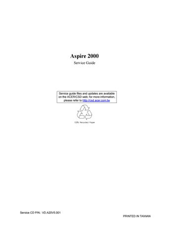
Jx1 Ix2 Hx1
ODD Module
Lx2 Mini Door Assy RAM Door Assy HDD Door Bus-Assuy Strip Cover Door Assy
Kx4
ODD Moduile ODD Panel Assy HDD Door Sub-Assy HDD Cover HDD Module
Bx2
Ax16
Display Assy Keyboard
Cx2
K/B Support Plate Assy
Px4
Dx13
Logic Assy
LCD Coaxial Cable
LCD Panel Hinge L Assy Hinge R Assy
LCD Cover Sub-Assy LCD Bezel Sub-Assy Ex1 Fx2
Logic Locu Assy VGA Board MDC Board Logic Up Assy
Mx2 Nx1 Ox2
Logic up Sub-Assy Sub-Woofer SD Board M/B Board Gx21
Speaker L Speaker R Deco Plate TP Support Assy Hinge Saddle R Assy Hinge Saddle L Assy TP FPC Assy
TP Board THML Fan Assy LCM Board Assy Front Button Board Front Button Board FFC Logic Up Sub-Assy
Item
A M2.5x5 M2.0x4 B M2.5x3 C M2.5x4 D M2.5x10 M2.5x4
Description
Item
E M2.5x14 F M2.0x4 G M2.5x4 H M2.5x14 I M2.5x10 J M2.5x5 K M3.0x3 L M2.0x3 M 2.5x4 N M2.5x4 O M2.5x5 P M2.5x4
Description
This section will guide you how to disassemble the system when you need to perform system service. Please also refer to the disassembly video, if availabled.
CAUTION: Before you proceed,make sure you have turned off the system and all peripherals connected.
Disassemble the Battery and HDD
1. Release the battery lock and slide the battery latch. 2. Then remove the battery pack. 3. Remove the two screws to release the hard drive door.Then take it away.
Disassemble the Wireless
1. Remove the one screw to release the mini door, and take it away. 2. Disconnect the two wireless cables. 3. Then take the wireless board from the base.
Disassemble the RAM and ODD
1. Remove the one screw to release the RAM door and remove it. 2. Press down the both side latches to release the RAM board. 3. Remove the one screw to release the ODD module. 4. Then push the inner position to remove the ODD from the base. 5. Pull the entire ODD moudle from the system.
Disassemble the Middle Cover Board
1. Remove the one screw. 2. Detach the middle cover from the unit with the flat screw driver. 3. Disconnect the system cable from the middle cover board. 4. Remove the two screws to release the middle cover board. 5. Then detach the middle cover board from cover.
Disassemble the Keyboard
1. Remove the screws on each side. 2. Pull up both sides of the latches to disconnect the FFC from the mainboard. 3. Remove the screws on each side to release the keyboard bracket. 4. Then take the keyboard supporter bracket from the system.
1. Remove the one screw from the LVDS board. 2. Pull the LCD coaxial board and the cable from the system. 3. Remove the two screws from the hinge on each side to release the LCD panel. 4. Pull the entire LCD module from the system.
Disassemble the MDC and RAM
1. Remove the two screws to release the MDC board. 2. Disconnect the MDC cable before you take the MDC board. 3. Press down the both sides latches to release the RAM. 4. Disconnect the right and left speaker cables from the mainboard. 5. Disconnect the touchpad FPC connector and CPU fan cable.
Disassemble the Upper Case
1. Remove the thirteen screws located on the base case. 2. Remove the two screws on the other side to located on the rear panel. 3. Remove the three screws to release the upper case. 4. Detach the upper case from the system.
1. Remove the seven screws to release the touchpad supporter bracket. 2. Disconnect the touchpad FPC connector. 3. Disconnect the cable as highlights. 4. Then detach the touchpad bracket from the position. 5. Detach the touchpad PC from the module. 6. Disconnect the bluetooth board FFC connector. 7. Remove the two screws to release the bluetooth board. 8. Take the bluetooth board from the system. 9. Remove the one screw to release the LCM board. 10. Detach the LCM board from the system.
1. Remove the one screw to release the up hinge saddle. 2. Remove the three screws to release the bottom hinge saddle. 3. Detach the right hinge saddle from the case. 4. Remove the two screws to release the right hinge saddle. 5. Take the right speaker from the opsition. 6. Remove the one screw to release the CPU fan from the hinge saddle. 7. Take the CPU fan from the hinge saddle.
8. Remove the three screws to release the left hinge saddle. 9. Detach the left hinge saddle from the system. 10. Remove the one screw to release the left speaker from the base cover. 11. Then detach the left speaker. 12. Remove the four screws to release the thermal module. 13. Detach the thermal module from the system. 14. Remove the one screw to release the CPU. 15. Detach the CPU fan from the socket.
1. Remove the one screw to release the VGA bracket. 2. Detach the VGA module from the mainboard. 3. Separate the VGA bracket and the VGA board.
4. Remove the ground screw to release the card reader. 5. Disconnect the card reader cables on each side. 6. Disconnect the sub-woofer cable 7. Remove the screws on each side to release the sub-woofer. 8. Detach the sub-woofer from the case. 9. Detach the card reader board from the case.
10. Remove the one screw to release the mainboard. 11. Press the PCMCIA button and hold the position to release the mainboard from the case.
1. Remove the screws on each side. 2. Detach the bezel from the LCD panel. 3. Remove the screws located on the different side. 4. Detach the LCD panel from the cover. 5. Take the antenna away from the position to release the inverter board. 6. Disconnect the LCD coaxial cables. 7. Remove the four screws to release the left LCD bracket. 8. Take the left LCD bracket from the panel. 9. Remove the four screws to release the right LCD bracket. 10. Take the right LCD bracket from the panel.
1. Remove the two screws to separate the ODD drive. 2. Detach the ODD bracket. 3. Detach the ODD door.
Disassemble the HDD Module
1. Remove the two screws on each side. 2. Separate the hard disk top cover and take the hard drive from the carrier. 3. Remove the hard disk connector from the rear position.