25 minute read
Chapter 3 Machine Disassembly and Replacement


Machine Disassembly and Replacement
This chapter contains step-by-step procedures on how to disassemble the notebook computer for maintenance and troubleshooting. To disassemble the computer, you need the following tools: Wrist grounding strap and conductive mat for preventing electrostatic discharge Number 1 Flat-bladed screwdriver Phillips screwdriver Plastic Flat-bladed screwdriver Number 5 Hexed screwdriver NOTE: The screws for the different components vary in size. During the disassembly process, group the screws with the corresponding components to avoid mismatch when putting back the components.
Before You Begin
Before proceeding with the disassembly procedure, make sure that you do the following: 1. Turn off the power to the system and all peripherals. 2. Unplug the AC adapter and all power and signal cables from the system.
The flowchart on the succeeding page gives you a graphic representation on the entire disassembly sequence and instructs you on the components that need to be removed during servicing. For example, if you want to remove the main board, you must first remove the keyboard, then disassemble the inside assembly frame in that order.
START
E*1 E*2 Modem
Cover
C*2 Middle Cover W/ Launch board
B*3 B*2 Launch Board DIMM Cover DIMM
Modem Board Keyboard Keyboard Bracket
C*2 DC-Charger Plate
D*4
CPU Fan Sink Module
C*4
VGA Thermal Plate DC to DC Board RTC Battery
CPU Battery Module
B*2 Battery cover Battery
Optical Drive Module
DVD:G*2 COMBO:G*3 CDROM:N/A
B*4 B*2 Optical Drive
Chassis Optical Drive PCB Optical Drive Bezel Touch Pad Frame
A*4
B*2 LCD Module
(See Next Page) Optical Drive
A*4 HDD Module
A*14 & B*1&C*2 I*4
Upper Case HDD Bracket HDD
Lower Case I/O Port bracket
J*2 C*1
C*2
PCMCIA Socket
C*2 C*1 C*2
FDD Module
H*2 Speakers Touch Pad Board
C*3
Main Board FDD FDD Bracket Touch Pad Buttons
Touch Pad Scroll Key
Touch Pad FPC
LCD Module LCD Module
LCD Cushions LCD Cushions
A*5
LCD Bezel LCD Bezel
F*4 A*1
LCD Hinges LCD Hinges Inverter Inverter
B*6 LCD Latch LCD Latch
LCD Coaxial LCD Coaxial Cable Cable LCD Panel LCD Panel
LCD LCD
Screw List
Item Description A Screw M2.5XL6 (Black) B Screw M2XL4 (Silver) C Screw M2XL5 (Silver) D Screw M2.5XL18 (Silver) E Screw M2XL4 (Black) F Screw M2.5XL5 (Black) G Screw M1.7XL3 (Black) H Screw M2.5XL4 (Silver) I Screw M3XL4 (Silver) J Hex Screw
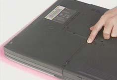
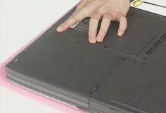
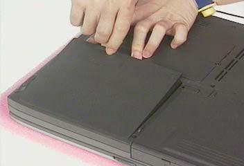
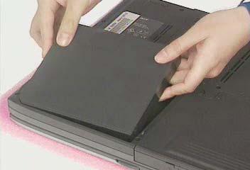
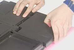
1. To remove the battery, first unlock the battery lock button, push the two battery release buttons, and then slide the battery pack out from the machine.
Disassembling the Battery Pack
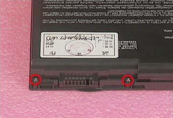
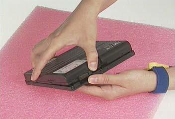
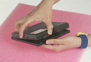
1. See “Removing the Battery Pack” on page 56 2. Remove the two screws, and then detach the battery from the battery cover.
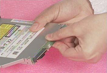
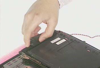
1. See “Removing the Battery Pack” on page 56 2. Release the release button and then slide the optical drive module out from the main unit.
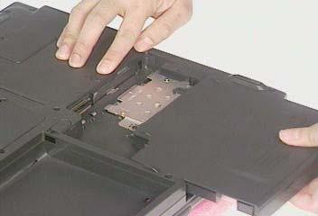
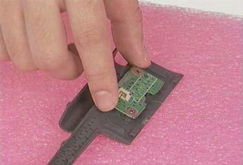
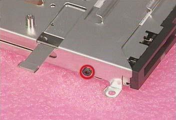
Disassembling the Optical Drive Module 1. See “Removing the Battery Pack” on page 56 2. See “Removing the Optical Drive Module” on page 57 3. To disassemble the optical drive module, first remove the four screws as shown.
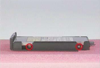
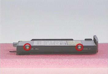
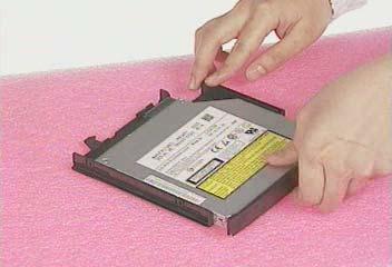
5. Remove the two screws and then detach the optical drive PCB from the optical drive module.

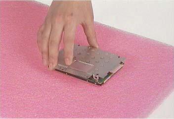
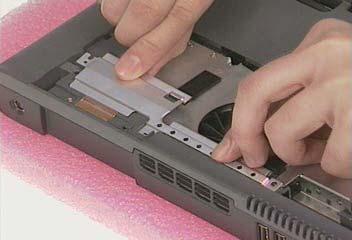
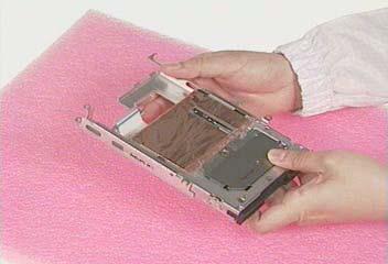
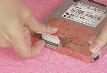
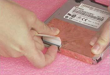
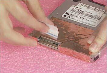
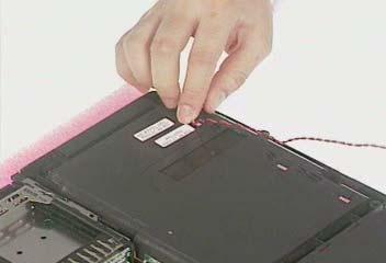
1. See “Removing the Battery Pack” on page 56 2. See “Removing the Optical Drive Module” on page 57 3. Remove the four screws as shown and then pull the plastic tag to detach the hard disk drive module out from the machine carefully.
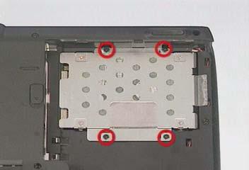
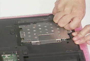
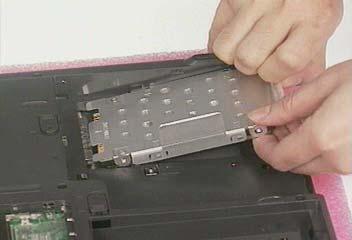
Disassembling the Hard Disk Drive Module
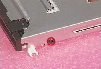
1. See “Removing the Battery Pack” on page 56 2. See “Removing the Optical Drive Module” on page 57 3. See “Removing the Hard Disk Drive Module” on page 58 4. To disassemble the hard disk drive module, first remove the four screws from the hard disk drive bracket.

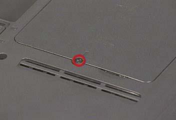
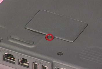
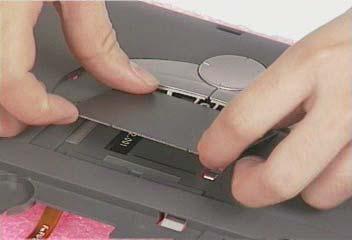
1. See “Removing the Battery Pack” on page 56 2. To remove the memory module from the machine, first remove the one screw from the memory cover.
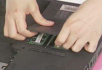
3. Lift the cover off, and then remove the memory cover.
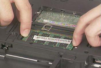
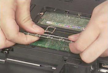
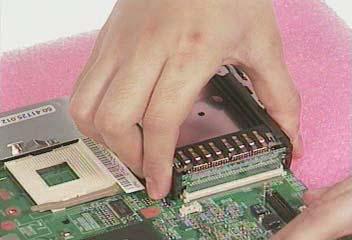
4. Push out the latches on both sides of the socket and pull the memory module out from the socket.
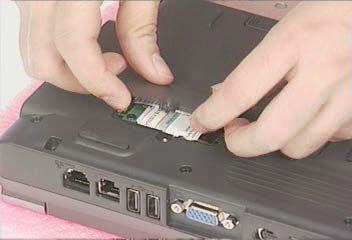
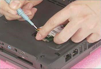
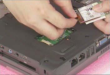
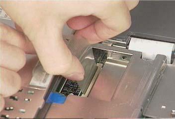
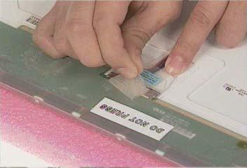
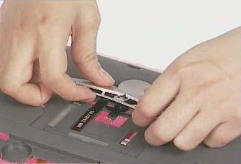
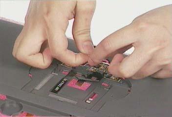
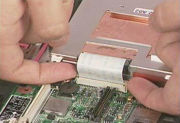
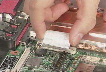
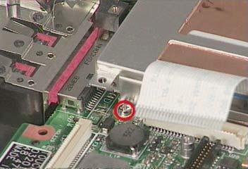
1. See “Removing the Battery Pack” on page 56 2. To remove the modem board, first remove the screw from the modem cover.
3. Remove the modem cover from the machine.
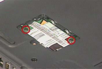
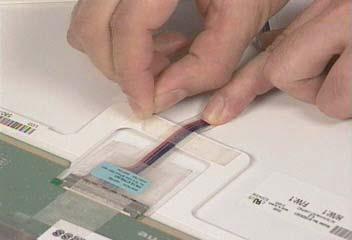
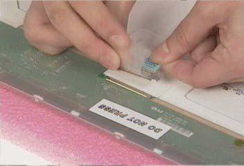
4. Remove two screws from the modem board as shown, disconnect the modem cable from the modem board, and then remove the modem board from the main unit carefully by using a plastic flat bladed screw driver.
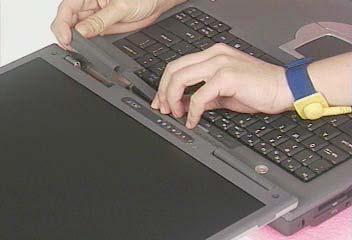
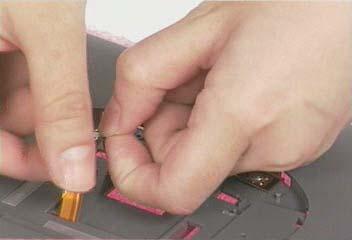
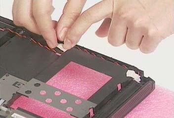
Removing the Middle Cover
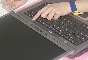
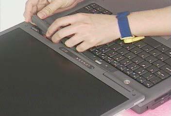
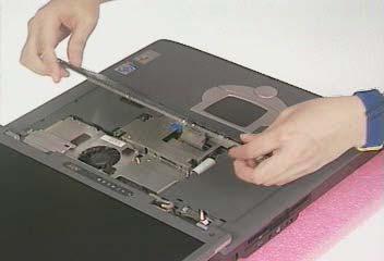
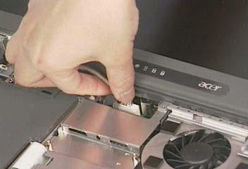
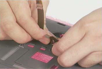
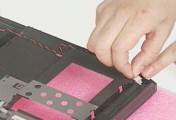
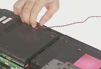
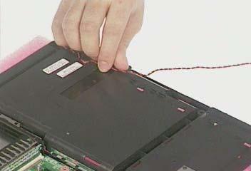
1. See “Removing the Battery Pack” on page 56 2. Pry up the middle cover with a plastic flat screwdriver, pull the middle cover up carefully
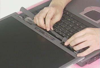
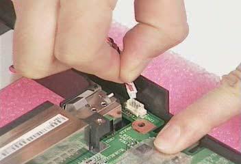
3. Turn the middle cover over and disconnect the launch board cable from the launch board and then detach the middle cover away from the main unit.
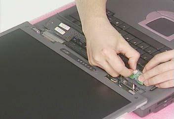
Removing the Launch Board
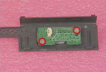
1. See “Removing the Battery Pack” on page 56 2. See “Removing the Middle Cover” on page 61 3. Remove the two screws and then detach the launch board from the middle cover.
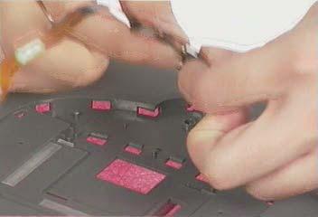
1. See “Removing the Battery Pack” on page 56 2. See “Removing the Middle Cover” on page 61 3. To remove the keyboard, first remove the three screws as shown here.
4. Lift the keyboard upward carefully and put it on the upper case.
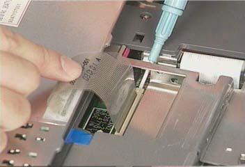
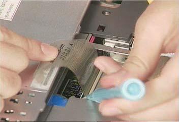
5. Use a plastic flat screwdriver to help disconnect the keyboard cable from the main board carefully, then remove the keyboard from the main board.

Removing the LCD Module
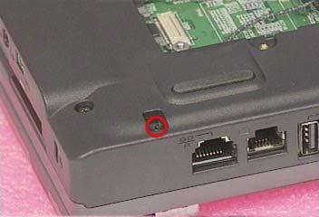
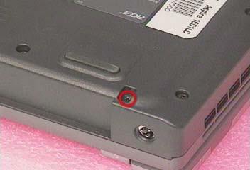
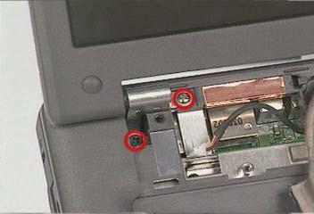
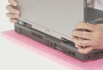
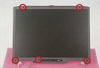
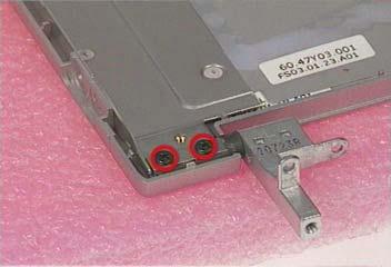
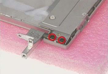
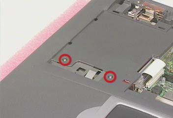
1. See “Removing the Battery Pack” on page 56 2. See “Removing the Middle Cover” on page 61 3. See “Removing the Keyboard” on page 62 4. Remove the two screws from the base of the unit.
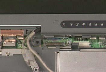
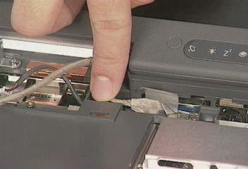
6. Remove the inverter cable from the main board with a plastic flat screwdriver.
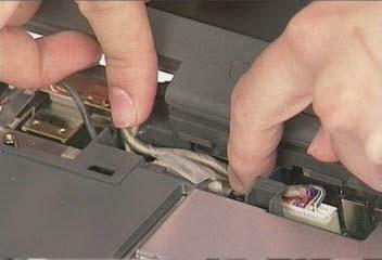
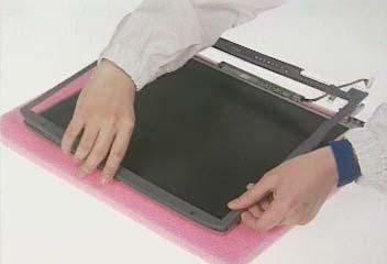
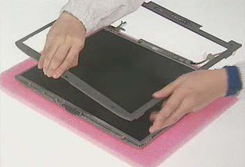
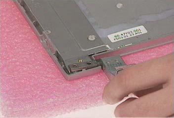
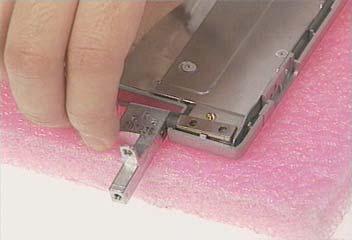
7. Remove the four screws as shown and then detach the LCD module from the main unit carefully.
NOTE: Please arrange the coaxial cable and the inverter cable well in the way as shown after you connect them to the main board.
Removing the LCD Bezel
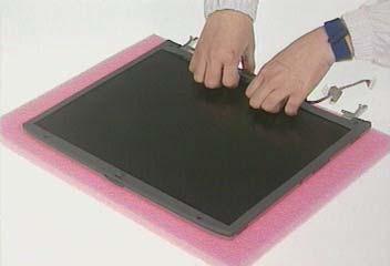
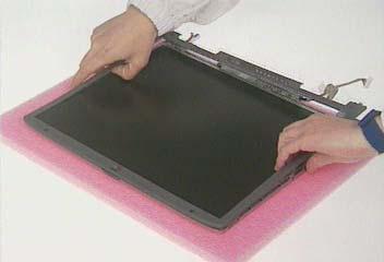
1. See “Removing the Battery Pack” on page 56 2. See “Removing the Middle Cover” on page 61 3. See “Removing the Keyboard” on page 62 4. See “Removing the LCD Module” on page 62 5. Remove the four LCD cushions as shown and the middle lower mylar on the LCD bezel, and then remove the five screws below from the LCD bezel.
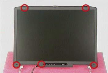
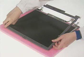
6. Snap off the bezel carefully, and then remove the LCD bezel from the LCD module.
Removing the Inverter Board
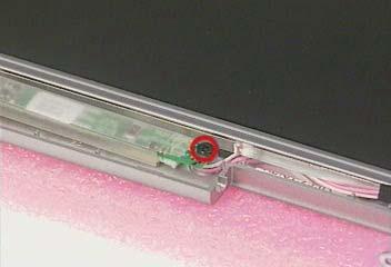
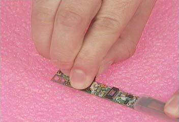
1. See “Removing the Battery Pack” on page 56 2. See “Removing the Middle Cover” on page 61 3. See “Removing the Keyboard” on page 62 4. See “Removing the LCD Module” on page 62 5. See “Removing the LCD Bezel” on page 63 6. To remove the inverter board, first remove the screw from the inverter board.
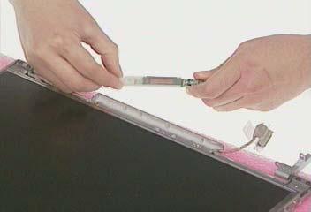
7. Disconnect the LCD power cable, remove the inverter board from the LCD panel, and then disconnect the inverter cable from the inverter board.
Removing the LCD
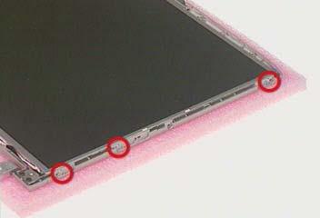
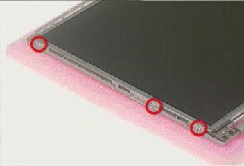
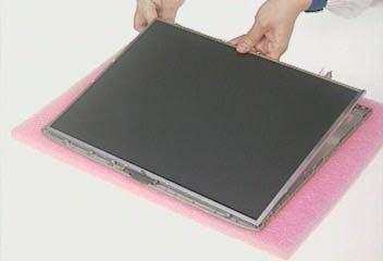
1. See “Removing the Battery Pack” on page 56 2. See “Removing the Middle Cover” on page 61 3. See “Removing the Keyboard” on page 62 4. See “Removing the LCD Module” on page 62 5. See “Removing the LCD Bezel” on page 63 6. See “Removing the Inverter Board” on page 64 7. To remove the LCD, first remove the six screws from both sides of the LCD, then remove the LCD from the LCD panel.
Removing the LCD Hinges
1. See “Removing the Battery Pack” on page 56 2. See “Removing the Middle Cover” on page 61 3. See “Removing the Keyboard” on page 62 4. See “Removing the LCD Module” on page 62 5. See “Removing the LCD Bezel” on page 63 6. Remove four screws to remove the LCD hinges and then detach the LCD hinges from the LCD.
Removing the LCD Coaxial Cable
1. See “Removing the Battery Pack” on page 56 2. See “Removing the Middle Cover” on page 61 3. See “Removing the Keyboard” on page 62 4. See “Removing the LCD Module” on page 62 5. See “Removing the LCD Bezel” on page 63 6. See “Removing the Inverter Board” on page 64 7. Remove the tapes then remove the LCD coaxial cable from the LCD.
Removing the Keyboard Bracket
1. See “Removing the Battery Pack” on page 56 2. See “Removing the Middle Cover” on page 61 3. See “Removing the Keyboard” on page 62 4. Remove the keyboard support bracket from the main unit carefully.
Removing the DC Charger Plate
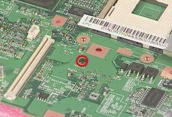
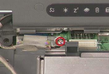
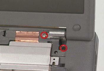
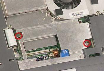
1. See “Removing the Battery Pack” on page 56 2. See “Removing the Middle Cover” on page 61 3. See “Removing the Keyboard” on page 62 4. See “Removing the LCD Module” on page 62 5. Remove the two screws as shown and then detach the DC charger Plate from the main board.
Removing the RTC Battery
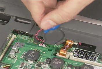
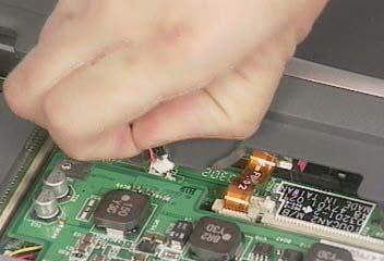
1. See “Removing the Battery Pack” on page 56 2. See “Removing the Middle Cover” on page 61 3. See “Removing the Keyboard” on page 62 4. See “Removing the Keyboard Bracket” on page 67 5. See “Removing the DC Charger Plate” on page 67 6. Disconnect the RTC cable and then remove the RTC battery from the upper case gently.
Removing the Touch Pad Frame
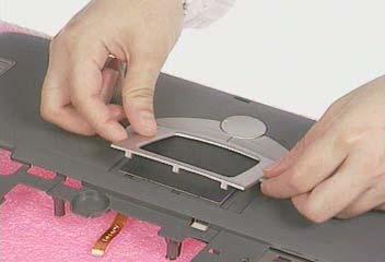
1. See “Removing the Battery Pack” on page 56 2. Release the latches with a plastic flat screwdriver carefully.
3. Detach the touch pad frame from the upper case gently.
Removing the DC to DC Board
1. See “Removing the Battery Pack” on page 56 2. See “Removing the Middle Cover” on page 61 3. See “Removing the Middle Cover” on page 61 4. See “Removing the Keyboard” on page 62 5. See “Removing the Keyboard Bracket” on page 67 6. Detach the DC to DC board from the main board gently.
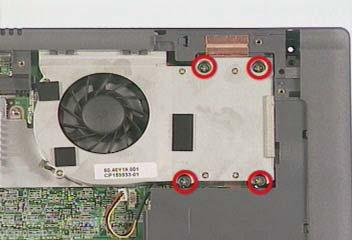
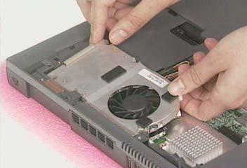
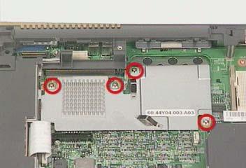
1. See “Removing the Battery Pack” on page 56 2. See “Removing the Middle Cover” on page 61 3. See “Removing the Keyboard” on page 62 4. See “Removing the Keyboard Bracket” on page 67 5. Disconnect the CPU fan cable, remove four screws, and then detach the CPU fan sink from the main unit.
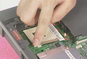
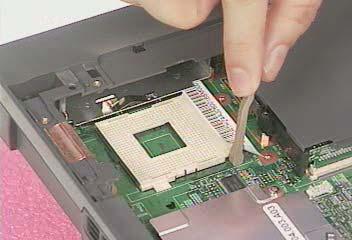
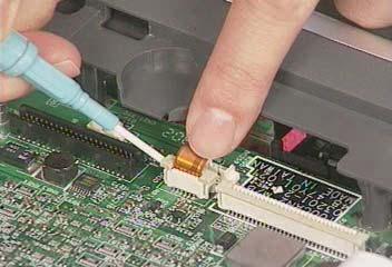
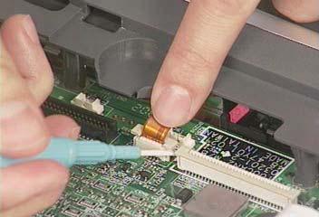
Removing the Processor
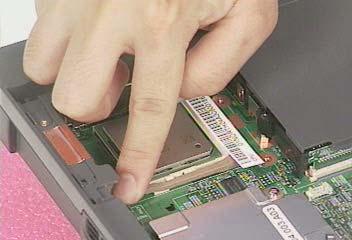
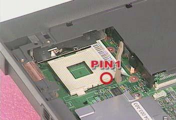
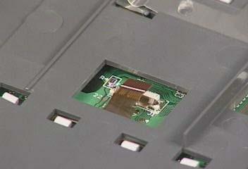
1. See “Removing the Battery Pack” on page 56 2. See “Removing the Middle Cover” on page 61 3. See “Removing the Keyboard” on page 62 4. See “Removing the Keyboard Bracket” on page 67 5. See “Removing the CPU Fan Sink” on page 69 6. Lift up the CPU socket lever, remove the CPU from the CPU socket carefully, and then put the CPU socket lever back to its original position.
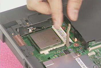
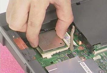
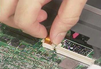
Installing the Processor
1. See “Removing the Battery Pack” on page 56 2. See “Removing the Middle Cover” on page 61 3. See “Removing the Keyboard” on page 62 4. See “Removing the Keyboard Bracket” on page 67 5. See “Removing the CPU Fan Sink” on page 69 6. Lift up the CPU socket lever, install the CPU to the CPU socket carefully, and then put the CPU socket lever back to its original position to secure the CPU well.
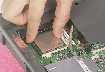
NOTE: Please make sure the CPU is attached with PIN1 on this side.
Removing the Upper Case
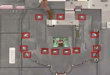
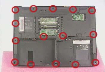
1. See “Removing the Battery Pack” on page 56 2. See “Removing the Optical Drive Module” on page 57 3. See “Removing the Hard Disk Drive Module” on page 58 4. See “Removing the Middle Cover” on page 61 5. See “Removing the Keyboard” on page 62 6. See “Removing the LCD Module” on page 62 7. See “Removing the Keyboard Bracket” on page 67 8. See “Removing the DC Charger Plate” on page 67 9. Use a plastic flat screwdriver to disconnect the touch pad cable from the main board.
10. To remove the upper case, first remove the two screws from the front side, and then remove the fifteen screws from the backside of the main unit.
Removing the Touch Pad Board
1. See “Removing the Battery Pack” on page 56 2. See “Removing the Hard Disk Drive Module” on page 58 3. See “Removing the Middle Cover” on page 61 4. See “Removing the Keyboard” on page 62 5. See “Removing the LCD Module” on page 62 6. See “Removing the Keyboard Bracket” on page 67 7. See “Removing the DC Charger Plate” on page 67 8. See “Removing the Touch Pad Frame” on page 68 9. See “Removing the Upper Case” on page 70 10. To detach the touch pad board, first disconnect the touch pad cable from the touch pad board with a plastic flat screwdriver and plastic tweezers, and then remove the touch pad board from the upper case.
Removing the Touch Pad Button
1. See “Removing the Battery Pack” on page 56 2. See “Removing the Hard Disk Drive Module” on page 58 3. See “Removing the Middle Cover” on page 61 4. See “Removing the Keyboard” on page 62 5. See “Removing the LCD Module” on page 62 6. See “Removing the Keyboard Bracket” on page 67 7. See “Removing the DC Charger Plate” on page 67 8. See “Removing the Touch Pad Frame” on page 68 9. See “Removing the Upper Case” on page 70 10. See “Removing the Touch Pad Board” on page 71 11. Remove the touch pad button.
Removing the Touch Pad Scroll Key
1. See “Removing the Battery Pack” on page 56 2. See “Removing the Hard Disk Drive Module” on page 58 3. See “Removing the Middle Cover” on page 61 4. See “Removing the Keyboard” on page 62 5. See “Removing the LCD Module” on page 62 6. See “Removing the Keyboard Bracket” on page 67 7. See “Removing the DC Charger Plate” on page 67 8. See “Removing the Touch Pad Frame” on page 68 9. See “Removing the Upper Case” on page 70 10. See “Removing the Touch Pad Board” on page 71 11. See “Removing the Touch Pad Button” on page 71 12. Detach the touch pad scroll key from the upper case.
Removing the Touch Pad FPC
1. See “Removing the Battery Pack” on page 56 2. See “Removing the Hard Disk Drive Module” on page 58 3. See “Removing the Middle Cover” on page 61 4. See “Removing the Keyboard” on page 62 5. See “Removing the LCD Module” on page 62 6. See “Removing the Keyboard Bracket” on page 67 7. See “Removing the DC Charger Plate” on page 67 8. See “Removing the Touch Pad Frame” on page 68 9. See “Removing the Upper Case” on page 70 10. See “Removing the Touch Pad Board” on page 71 11. See “Removing the Touch Pad Button” on page 71 12. Detach the touch pad FPC from the upper case carefully.
Removing the VGA Thermal Plate
1. See “Removing the Battery Pack” on page 56 2. See “Removing the Hard Disk Drive Module” on page 58 3. See “Removing the Middle Cover” on page 61 4. See “Removing the Keyboard” on page 62 5. See “Removing the Keyboard Bracket” on page 67 6. See “Removing the DC Charger Plate” on page 67 7. See “Removing the CPU Fan Sink” on page 69 8. Remove the four screws and then detach the VGA thermal plate from the main board.
Removing the Floppy Disk Drive Module
1. See “Removing the Battery Pack” on page 56 2. See “Removing the Optical Drive Module” on page 57 3. See “Removing the Hard Disk Drive Module” on page 58 4. See “Removing the Middle Cover” on page 61 5. See “Removing the Keyboard” on page 62 6. See “Removing the LCD Module” on page 62 7. See “Removing the Keyboard Bracket” on page 67 8. See “Removing the DC Charger Plate” on page 67 9. See “Removing the Upper Case” on page 70 10. Disconnect the FDD cable from the main board and remove the one screw.
11. Detach the FDD module from the lower case.

Disassembling the Floppy Disk Drive Module 1. See “Removing the Battery Pack” on page 56 2. See “Removing the Optical Drive Module” on page 57 3. See “Removing the Hard Disk Drive Module” on page 58 4. See “Removing the Middle Cover” on page 61 5. See “Removing the Keyboard” on page 62 6. See “Removing the LCD Module” on page 62 7. See “Removing the Keyboard Bracket” on page 67 8. See “Removing the DC Charger Plate” on page 67 9. See “Removing the Upper Case” on page 70 10. See “Removing the Floppy Disk Drive Module” on page 73 11. To disassemble the floppy disk drive from the disk drive module, first remove the two screws as shown here and then detach the floppy disk from the floppy disk drive bracket
12. Disconnect the floppy disk drive FPC cable gently from the floppy disk drive.
Removing the Speakers
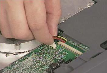
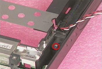
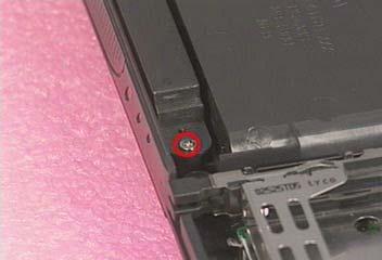
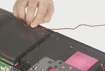
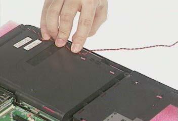
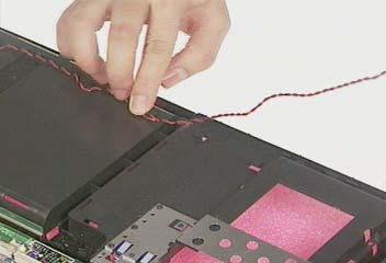
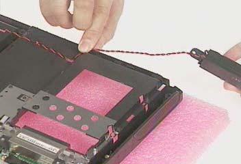
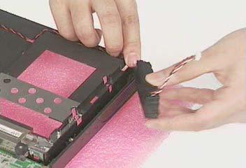
1. See “Removing the Battery Pack” on page 56 2. See “Removing the Optical Drive Module” on page 57 3. See “Removing the Hard Disk Drive Module” on page 58 4. See “Removing the Middle Cover” on page 61 5. See “Removing the Keyboard” on page 62 6. See “Removing the LCD Module” on page 62 7. See “Removing the Keyboard Bracket” on page 67 8. See “Removing the DC Charger Plate” on page 67 9. See “Removing the Upper Case” on page 70 10. To remove the speakers, first remove the two tapes, disconnect the cable from the main board and then remove the two screws.
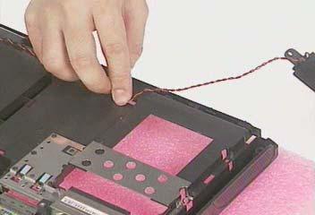
11. Remove the speakers and speaker cable from the lower case gently.
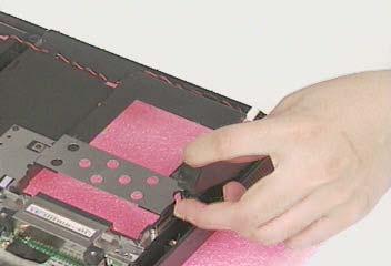
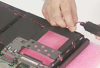
NOTE: Please pay attention to how the speaker cable is routed when the speakers are attached back to the main unit.
Removing the Main Board
1. See “Removing the Battery Pack” on page 56 2. See “Removing the Optical Drive Module” on page 57 3. See “Removing the Hard Disk Drive Module” on page 58 4. See “Removing the Middle Cover” on page 61 5. See “Removing the Keyboard” on page 62 6. See “Removing the LCD Module” on page 62 7. See “Removing the Keyboard Bracket” on page 67 8. See “Removing the DC Charger Plate” on page 67 9. See “Removing the DC to DC Board” on page 68
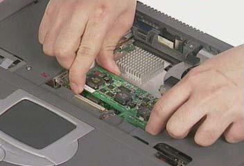
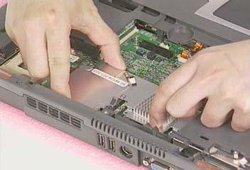
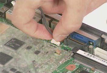
10. See “Removing the Upper Case” on page 70 11. See “Removing the Floppy Disk Drive Module” on page 73 12. See “Removing the VGA Thermal Plate” on page 73 13. Disconnect the launch board cable and the speaker cable from the main board.
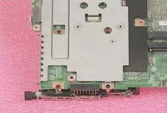
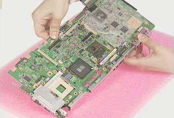
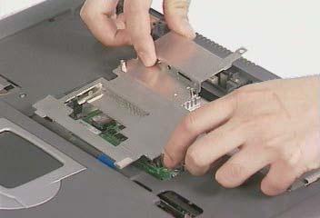
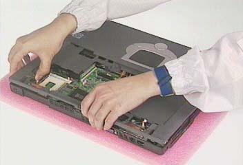
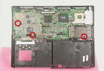
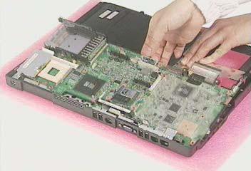
14. Remove the three screws as shown and detach the main board from the lower case carefully in the way as shown here.
Removing the PCMCIA Slot
1. See “Removing the Battery Pack” on page 56 2. See “Removing the Optical Drive Module” on page 57 3. See “Removing the Hard Disk Drive Module” on page 58 4. See “Removing the Middle Cover” on page 61 5. See “Removing the Keyboard” on page 62 6. See “Removing the LCD Module” on page 62 7. See “Removing the Keyboard Bracket” on page 67 8. See “Removing the DC Charger Plate” on page 67 9. See “Removing the DC to DC Board” on page 68 10. See “Removing the Upper Case” on page 70 11. See “Removing the Floppy Disk Drive Module” on page 73 12. See “Removing the VGA Thermal Plate” on page 73 13. See “Removing the Main Board” on page 76 14. Remove four screws from the PCMCIA plate to remove the plate.
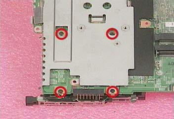
15. Detach the PCMCIA slot from the main board.
Removing the I/O Port Bracket
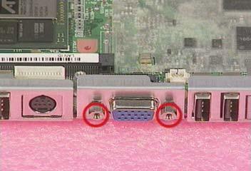
1. See “Removing the Battery Pack” on page 56 2. See “Removing the Optical Drive Module” on page 57 3. See “Removing the Hard Disk Drive Module” on page 58 4. See “Removing the Middle Cover” on page 61 5. See “Removing the Keyboard” on page 62 6. See “Removing the LCD Module” on page 62 7. See “Removing the Keyboard Bracket” on page 67 8. See “Removing the DC Charger Plate” on page 67 9. See “Removing the DC to DC Board” on page 68 10. See “Removing the Upper Case” on page 70 11. See “Removing the Floppy Disk Drive Module” on page 73 12. See “Removing the VGA Thermal Plate” on page 73 13. See “Removing the Main Board” on page 76 14. Remove the two screws as shown.
15. Remove the two hex screws and the other one screw as shown to detach the I/O port bracket from the main board.