3 minute read
1–1 General Troubleshooting Information

from Allison Transmission JA3664EN 1000 & 2000 Product Families In-chassis Maintenance Manual - DOWNLOAD

TROUBLESHOOTING
SECTION I
1–1. GENERAL TROUBLESHOOTING INFORMATION
a. CHECK TRANS Light. The CHECK TRANS light is original equipment manufacturer (OEM)-supplied and usually located on the vehicle’s instrument panel.
The CHECK TRANS light is illuminated briefly during vehicle start-up as a bulb check.
NOTE: The CHECK ENGINE light may serve the CHECK TRANS function for vehicles which are compliant to Industry On Board Diagnostics II (OBD-II) requirements.
When the light is “ON” shifts may be restricted by the Transmission Control Module (TCM) when the TCM senses abnormal conditions as follows:
WARNING: If ignition is turned “OFF” and then “ON” while the CHECK TRANS light is displayed, the transmission may remain in neutral until the code is cleared. Leave ignition “ON” until you are in a safe place to stop.
• The transmission may be locked in the range it was in when the problem was detected. • The transmission may continue to operate with inhibited shifting. • The TCM may not respond to shift selector requests. • Direction changes and shifts from neutral-to-range may not occur.
Whenever the CHECK TRANS light is displayed, the TCM logs a diagnostic code in memory. These diagnostic codes can be accessed through the Allison DOC™ For PC diagnostic system.
NOTE: Diagnostic codes can be logged without illuminating the CHECK TRANS light. This occurs when the TCM senses a problem, but determines the problem won’t cause immediate transmission damage or dangerous performance.
b. Range Inhibit Indicator. If the TCM detects conditions such that a shift from Neutral to a forward range or to Reverse should not be allowed, shifts out of Neutral may be inhibited. At the same time these events occur, a required OEM-supplied RANGE INHIBITED light, mounted on the dash or near the shift selector, is illuminated. This notifies the driver that shifting is inhibited and the shift selector may not respond to shifts requested. c. Allison Diagnostic Optimized Connection™ (Allison DOC™ For PC). Control system diagnostics are performed using a “Windows” PC operating system and interface/software which is available through Allison Transmission tool sources. The PC acts as a receiver/transmitter/display medium that allows the service technician to communicate with the TCM. Typical troubleshooting activities performed are installation checkout and diagnostic code retrieval.
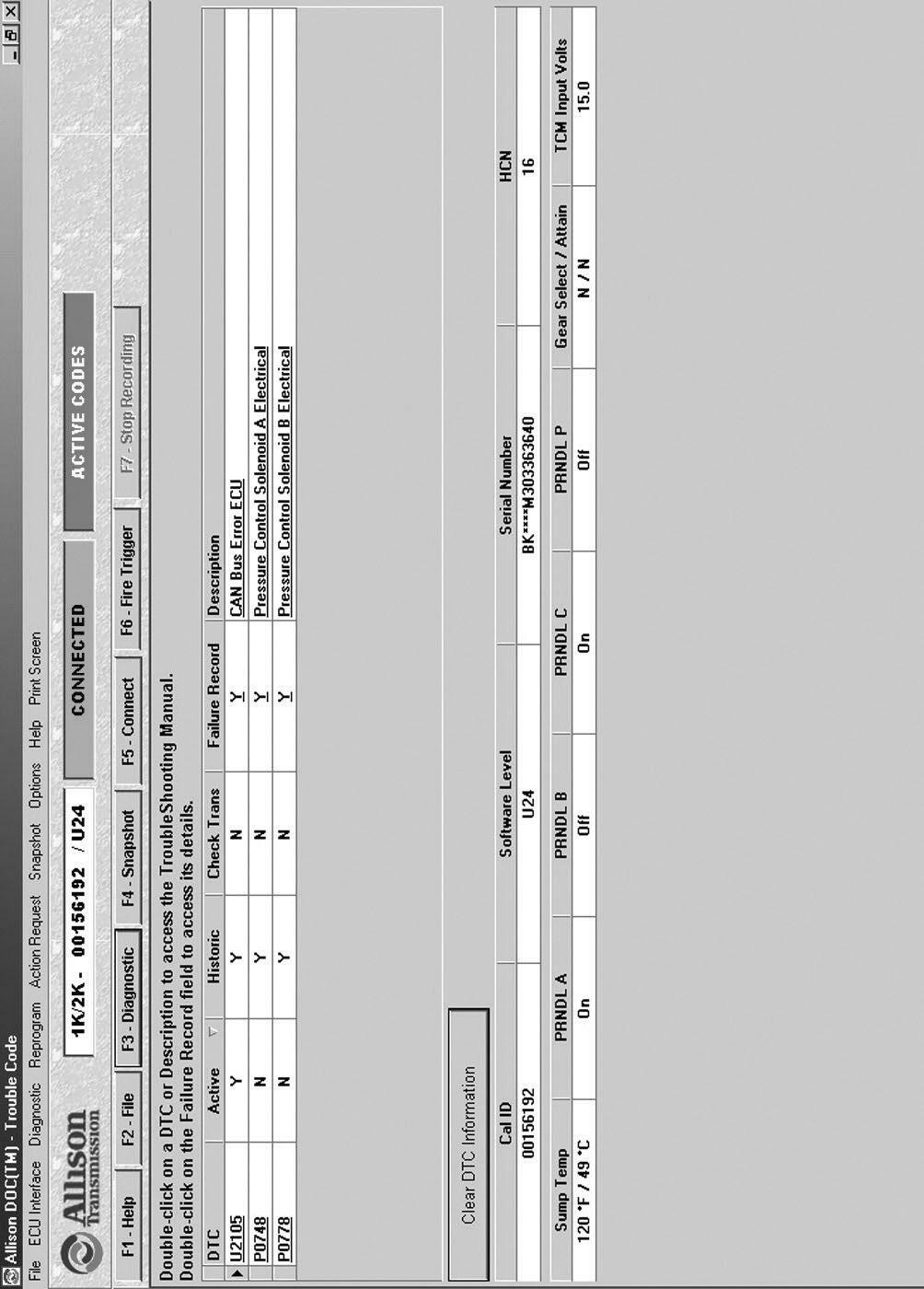
Consult the User Guide which accompanies the Allison DOC™ For PC diagnostic tool. Figure 1–1 shows a typical beginning screen for the Allison DOC™ for PC diagnostic tool. The user’s manual contains the information for performing the following:
• Displaying (retrieving) diagnostic trouble codes (DTCs) Transmission diagnostic codes begin with P0, P1, U1, or U2 followed immediately by three additional numbers. For a complete list of codes and more detailed information, refer to TS3192EN, Electronic Troubleshooting Manual. • Clearing diagnostic codes • Obtaining transmission data such as input speed or sump fluid temperature • Conducting solenoid testing • Conducting clutch diagnostics (including torque converter clutch)
Figure 1–1. Trouble Code Screen—Allison DOC™ For PC
d. Troubleshooting When No Diagnostic Codes Are Present. • Always start with the basics: — Make sure the shifter is in the appropriate range. — Check the fluid level. — Make sure batteries are properly connected and charged.
— Make sure throttle is closed and engine speed is below 900 rpm. — Make sure electrical connections are properly made. — Check support equipment for proper installation and operation. • If adaptive information had been reset, initial upshifts and downshift may be harsh. Allow shifts to “converge” before assuming there is a shift problem. • Refer to Paragraph 1–2 “General Troubleshooting of Performance Complaints.” — These troubleshooting charts list a variety of conditions that may or may not relate to the Electronic Control. — Some conditions and suggested checks include mechanical and hydraulic items. • If the troubleshooting charts refer you to an Electronic Control check, use the diagnostic code troubleshooting information that best applies to the situation. e. Troubleshooting Intermittent Diagnostic Codes. Intermittent codes are a result of conditions which are not always present. When conditions causing the code exist, the code is logged in memory. The code stays in memory until it is manually cleared or cycled out. When intermittently occurring codes exist, check for the following items: • Dirty, damaged or corroded harness connectors and terminals • Terminals not fully seated in connectors • Damaged harnesses (due to poor routing, chafing, excessive heat, tight bends, etc.) • Improperly mounted electronic control components • Poor connector seals (where applicable) • Exposed harness wires • Electromagnetic Interference (EMI) generating components and accessories • Loose ground connections
To help locate intermittents, it sometimes helps to place the appropriate tester on the suspect component or circuit and simulate operating conditions — wiggle, pull, bump, and bend while watching the tester.