2 minute read
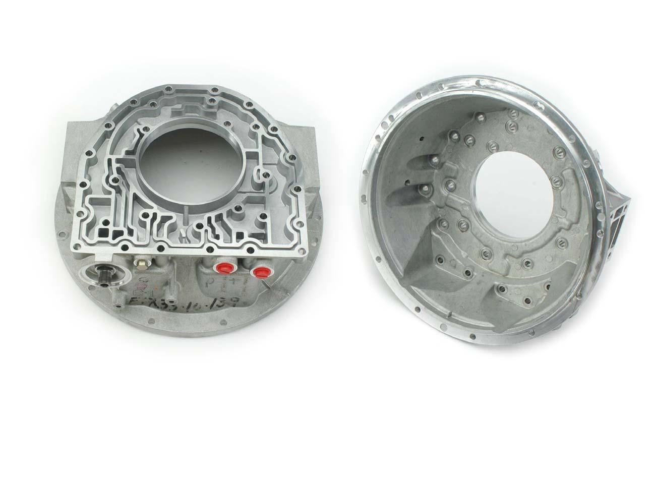
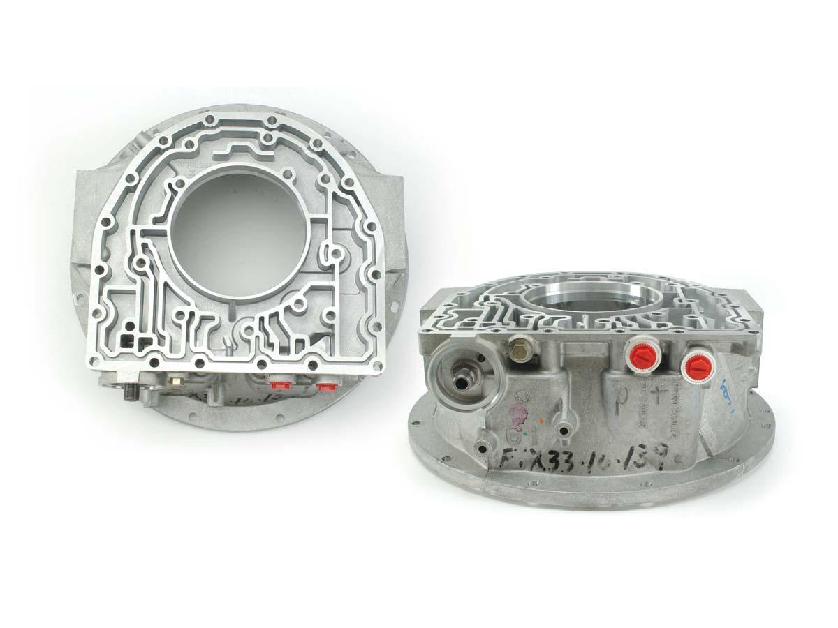
Torque Converter Housing


A. Housing B. Machined Sealing Surface B. Machined
Mounting
Surface
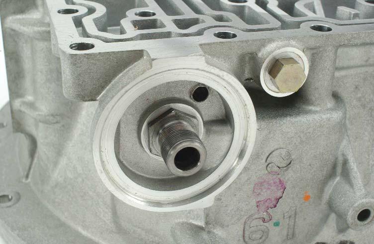
D. Filter
Attachment
Tube C. Cooler Ports and Pressure
Tap Threads
A. Inspect the housing for impact damage, chips and cracks. Inspect bolt holes for damaged threads. Replace the housing if damage cannot be repaired. B. Inspect machined surfaces for damage which might prevent proper sealing and/or seating. Inspect for deep scratches, scoring, grooves, nicks, burrs, chips and cracks. Replace the housing if damage cannot be repaired using a soft stone or crocus cloth.
C. Inspect cooler port and pressure tap threads for stripping and damage. Replace the housing if damage cannot be repaired. Some models use a cooler manifold which bolts to the torque converter housing. When used, inspect the cooler manifold cooler port and pressure tap threads for stripping and damage. Inspect the manifold channel plate for scratches, burrs and damage. Replace the manifold if damage cannot be repaired.
(continued)
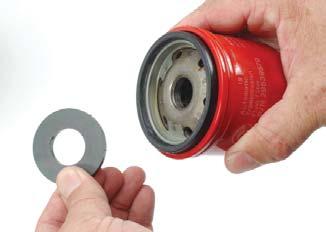
A magnet sits on top of the control main filter and fits over the filter attachment tube.
Knockdown (Overdrive)
N/A
Exhaust or Drain Back
Main Pressure
Lube Pressure Exhaust
Overage Oil Passage Detail
Exhaust or Drain Back
Suction
From Cooler
From Control Main Filter
To Control Main Filter
Main Pressure N/A
To Cooler
C1 Pressure C2 Pressure To Control Main Filter
From Control Main Filter
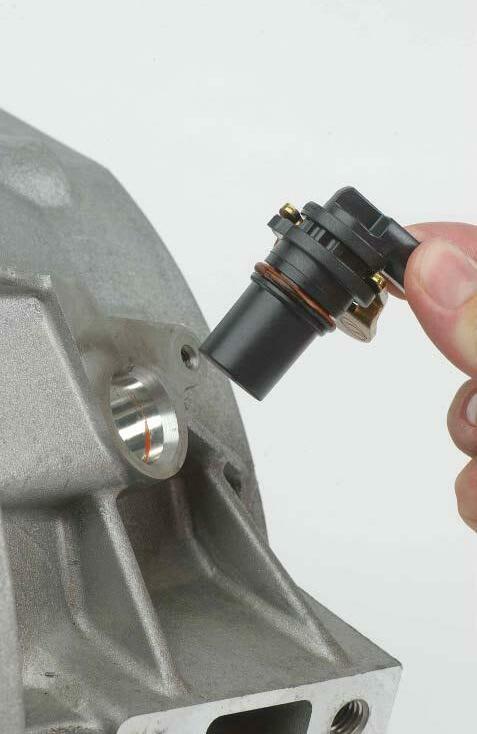
F. Input
Speed
Sensor
E. Input
Speed
Sensor
Bore
D. Inspect the filter attachment tube threads for stripping and damage. Replace the fitting if damage cannot be repaired. Replace the housing if the threaded bore is damaged and cannot be repaired. E. Inspect the input speed sensor bore for scoring, nicks, burrs, chips or cracks. Replace the housing if the damage cannot be repaired using a soft stone or crocus cloth. F. Inspect the input speed sensor for obvious external damage. Inspect the seal ring for wear, damage and proper fit on the sensor and in the speed sensor bore. Speed sensor resistance can be checked using an ohmmeter. Reference Troubleshooting Manual TS3192 for procedures and specifications.