1 minute read
Chapter 11 Storage


Chapter 8 - Operation
Step 1
Put the machine on firm, level surface, and move the boom to a position where it is easy to adjust.
Step 2
Using the level adjustment switch, adjust the level of the platform.
4–9 Bleeding air from the platform leveling system
If the platform begins to lean soon after the inclination has been adjusted, air may have entered the platform leveling device. If this is the case, do the following to bleed the air from the platform balancing device.
Step 1
Put the machine on firm, level surface, and move the boom to a position where it can be adjusted easily.
Step 2
Use the lower control panel leveling adjustment switch to incline the platform completely forward, and completely backwards. Repeat this 3 or 4 times.
Step 3
Adjust the platform so it becomes level.
Step 4
Completely raise and lower, and fully extend and retract the boom a few times, and check the levelness of the platform.
5. Towing
If you are unable to travel the machine because of problems, it is possible to tow the machine provided you release the brake. Do the following.
5–1 Releasing the brake DANGER
• Do not release the brake on sloped ground. The machine may roll away uncontrollably, and it is very dangerous. • Do not use a cable to tow on sloped ground because it is dangerous.
CAUTION
• In order to steer while being towed, be careful to avoid having the tow rod etc. come into contact with the machine. • Once the brake has been released, do not travel the machine using the control panel. It will cause trouble.
Free the parking brake and steering linkage, then tow the machine to escape the machine from working site, when the travel function is disabled.
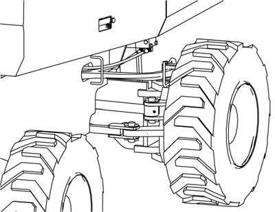
5-1-2 Free the steering linkage
(1) Remove the steering lock pin Free the parking brake by Parking brake release hand pump.
Tie rod
Steering cylinder
Steering lock pin
fig. 8-21
M083E200
(1) Set up the wheel chocks in front and rear of all tires. (2) Open the right rear cover. (3 Loosen the lock nut behind the HST pump, and then screw in the bolt to push the HST pump release pin on the relief valve R1 and R2.
36