22 minute read
Chapter 1 System Specifications


System Specifications
Features
Advertisement
This computer was designed with the user in mind. Here are just a few of its many features:
Performance ! Intel® Mobile Pentium® IV Northwood processor-M with 512 KB L2 cache and Intel® SpeedStepTM technology support ! 64-bit memory bus ! Memory expandable up to 1GB ! Internal removable optical drive (removable CD or DVD drive) ! External USB floppy drive ! High-capacity, Enhanced-IDE hard disk ! Li-Ion main battery pack ! Power management system with ACPI (Advanced Configuration Power Interface) ! Smart Card interface with pre-boot authentication systems as security feature
Display
! Thin-Film Transistor (TFT) liquid crystal-display (LCD) displaying 16-bit high color up to 1024X768 extended Graphics Array+ (XGA) resolution for 14.1” and 1400X1050 Super extended Graphics Array+ (SXGA+) resolution for 15”. ! 3D capabilities ! Simultaneous LCD and CRT display support ! S-video for output to a television or display device that supports S-video input. ! “Automatic LCD dim” feature that automatically decides the best settings for your display and conserves power ! Dual display capability
Multimedia
! 16-bit high-fidelity AC’97 stereo audio with 3D sound and wavetable synthesizer. ! Built-in dual speakers ! Built-in microphone ! High-speed optical drive (AcerMedia bay)
Connectivity ! High-speed fax/data modem port ! Fast infrared wireless communication ! Dual USB (Universal Serial Bus) ports ! Ethernet/Fast Ethernet port ! IEEE1394 port ! Optional 802.11b wireless LAN
Expansion
! One type II CardBus PC Card slot ! One SmartCard slot ! Upgradeable memory ! Removable drives ! EasyPort port replicator
Keyboard and Pointing Device
! 84-/85-key PS/2 and AT-compatible Windows keyboard ! Ergonomically-centered touchpad pointing device with a 4-way scroll key function
I/O Ports
! One type II CardBus PC Card slot(s) ! One RJ-45 jack for Ethernet ! One RJ-11 phone jack for 56kbps fax/modem ! One DC-in jack (AC adapter) ! One parallel port (ECP/EPP compliant) ! One external monitor port ! One audio line-out jack ! One microphone-in jack ! Two USB ports ! One port replicator connector ! One firewire 1394 port ! One S-video output port ! One RF receiver socket* ! One SmartCard reader ! One FIR port ! One Kensington lock. NOTE: *: RF receiver socket is for radio frequency controller, which can remote turn on/off the computer.
Top View
1 IEEE 1394 17 SW2 Setting 2 Line-in Port 18 Touch Pad Connector 3 Line-out Port 19 External CD/DVD-ROM Module Connector 4 Parallel Port 20 Speaker Connector 5 LCD Coaxial Cable Connector 21 Daughter Board Connector (on main board, under daughter board) 6 Port Replicator 22 Speaker Connector 7 CRT Connector 23 Battery Connector 8 TV-out Port 24 Keyboard Connector 9 USB Port 25 RTC Battery Connector 10 DC-in Port 26 Cardbus/SmartCard Socket 11 LCD Cover Switch Connector 27 Cardbus connector 12 Microphone-in Port 28 USB Port 13 LED/Inverter Board Connector 29 Mini PCI Connector 14 CPU Socket 30 Golden Finger 15 FAN Connector 31 HDD Connector 16 North Bridge
1 Modem Connector 5 DIMM socket 2 2 Modem Connector 6 RF Module Connector 3 DIMM Socket 1 7 FIR 4 Modem Board Socket
A general introduction of ports allow you to connect peripheral devices, as you would with a desktop PC.
Front View

# Icon Item Description
1 Display screen Also called LCD (liquid-crystal display), diplays computer output. 2 Status indicators LEDs (light-emitting diode) that turn on and off to show the status of the computer, its functions and components. 3 Launch Keys Special Keys for launching internet browser, email program and frequently used programs. See “Launch Keys” on page 17 for more details. 4 Touchpad Touch-sensitive pointing device which functions like a computer mouse.
5 Click buttons (left, center and right)
The left and right buttons function like the left and right mouse buttons; the center button serves as a 4 way scroll button. 6 Infrared port Interfaces with infrared devices (e.g., infrared printer, IR-aware computer).
7 Speaker Outputs sound 8 Palmrest Comfortable support area for your hands when you use the computer. 9 Keyboard Inputs data into your computer.

# Icon Item Description 1 Hard Disk Bay Houses the computer’s removable hard disk (secured by a screw). 2 USB port Connect to Universal Serial Bus devices (e.g., USB mouse, USB camera). 3 PC Card Eject buttons Eject the selected PC Card from the slot. 4 PC Card slot Accept one type III or 16-bit PC Card or 32-bit CardBus PC Card. 5 Smart Card Eject button Ejects the SmartCard from the slot. 6 Battery bay Houses the computer’s battery pack. 7 Video capture kit slot Accepts the video capture kit option on the left side of the computer. 8 Smart Card Slot Slot for Smart Card interface with pre-boot authentication systems.

# Item Description 1 AcerMedia drive bay Houses a removable media drive module. 2 AcerMedia indicator Lights up when the AcerMedia drive is active. 3 Eject button Ejects the drive tray. 4 Emergency eject slot Ejects the drive tray when the computer is turned off. 5 Power switch Turns on the computer power. 6 Security keylock Connects to a Kensington-compatible computer security lock.
NOTE: The positions of the AcerMedia indicator, eject button and emergency eject hole may differ depending on hte optical drive module installed.

# Icon Item Description 1 Power jack Connects to an AC adapter
2 USB ports (two) Connect to Universal Serial Bus devices (e.g., USB mouse, USB camera).
3 S-video port Connects to a television or display device with Svideo input.
4 External display port Connects to a display device (e.g., external monitor, LCD projector) and displays up to 16.7 million colors at 1400x1050 resolution.
5 Easy Link Port/ Replicator Port I/O replicator for EasyPort expansion devices.
6 Parallel port Connects to a parallel device (e.g., parallel printer).
7 Speaker/Headphone-out jack Connects to audio line-out devices (e.g., speakers, headphones).
8 Line-in jack Accepts audio line-in devices (e.g., audio CD player, stereo walkman).
9 Modem jack Connects to a phone line.
10 Network jack Connects to an Ethernet 10/100-based network
11 IEEE 1394 Port Connects to IEEE 1394 devices.


# Icon Item Description 1 Cooling fan Helps keep the computer cool*. 2 AcerMedia bay release latch Unlatches the AcerMedia drive for removal or swapping. 3 AcerMedia bay Houses an AcerMedia drive module. 4 Personal identification slot Insert a business card or similar-sized identification card to personalize your computer. 5 Battery release latch Unlatches the battery to remove the battery pack. 6 Battery bay Houses the computer’s battery pack. 7 Memory compartment Houses the computer’s main memory. 8 Hard disk bay Houses the computer’s hard disk. (Secured by a screw) 9 Hard disk protector Protects the hard disk from accidental bumps and vibration.
NOTE: *: Do not cover or obstruct the opening of the fan.
The computer has seven easy-to-read status icons on the right of the display screen.
The Power and Sleep status icons are visible even when you close the display cover so you can see the status of the computer while the cover is closed.
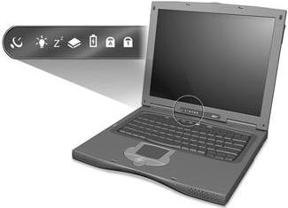
# Icon Function 1 Wireless Communication Lights when the Blue-Tooth/Wireless LAN capabilities are enabled.
2 Power Lights when the computer is on. Blinks when a battery-low condition occurs.
3 Sleep Lights when the computer enters Standby mode and blinks when it enters into or resumes from hibernation mode. 4 Media Activity Lights when the floppy drive, hard disk or AcerMedia drive is active.
5 Battery Charge Lights when the battery is being charged.
6 Caps Lock Lights when Caps Lock is activated.
7 Num Lock Lights when Num Lock is activated.
Description
The keyboard has three lock keys which you can toggle on and off.
Lock Key
Description @ @ @ @ When @ @ @ @ is on, all alphabetic characters typed are in uppercase. ] ] ] ]
(Fn-F11)
(Fn-F12) When ] ] ] ] is on, the embedded keypad is in numeric mode. The keys function as a calculator (complete with the arithmetic operators +, -, *, and /). Use this mode when you need to do a lot of numeric data entry. a better solution would be to connect an external keypad. When [ [ [ [ is on, the screen moves one line up or down when you press the up or down arrow keys respectively. [ [ [ [ does not work with some applications.
The embedded numeric keypad functions like a desktop numeric keypad. It is indicated by small characters located on the upper right corner of the keycaps. To simplify the keyboard legend, cursor-control key symbols are not printed on the keys.
Desired Access Num Lock On
Number keys on embedded keypad Cursor-control keys on embedded keypad Type numbers in a normal manner.
Hold j j j j while using cursor-control keys. Main keyboard keys Hold Fn while typing letters on embedded keypad. Num Lock Off
Hold Fn while using cursor-control keys.
Type the letters in a normal manner.
NOTE: If an external keyboard or keypad is connected to the computer, the ] ] ] ] feature automatically shifts from the internal keyboard to the external keyboard or keypad.
The keyboard has two keys that perform Windows-specific functions.
Key Icon Description Windows logo key Start button. Combinations with this key perform shortcut functions. Below are a few examples: ! + Tab (Activates next taskbar button) Windows + E (Explores My Computer) ! + F (Finds Document) ! + M (Minimizes All) j j j j + ! + M (Undoes Minimize All) ! + R (Displays the Run...dialog box)
Application key Opens a context menu (same as a right-click).
The computer employs hot keys or key combinations to access most of the computer’s controls like screen contrast and brightness, volume output and the BIOS Utility. To activate hot keys, press and hold the Fn key before pressing the other key in the hot key combination.
Hot Key Icon Function Description
Fn-F1 Hot key help Displays a list of the hotkeys and their functions.
Fn-F2 Setup Accesses the notebook’s configuration utility.
Fn-F3 Power Management Scheme Toggle
Switches the power management scheme used by the computer (function available if supported by operating system). Fn-F4 Sleep Puts the computer in Sleep mode, which can be defined via the advanced section of the Power Management Properties in the Windows Control Panel. Fn-F5 Display toggle Switches display output between the display screen, external monitor (if connected) and both the display screen and external monitor. Fn-F6 Screen blank Turns the display screen backlight off to save power. Press any key to return.
Fn-F7 Touchpad toggle Turns the internal touchpad on and off. When you connect an external PS/2 mouse, the computer automatically disables the touchpad. Fn-F8 Speaker toggle Turns the speakers on and off; mutes the sound.
Fn-up Volume up Increases the speaker volume.
Fn-down Volume down Decreases the speaker volume.
Fn-→ Brightness up Increases the screen brightness.
Hot Key Icon Function Description
Fn-← Brightness down Decreases the screen brightness.
Located at the top of the keyboard are five buttons. These buttons are called launch keys. They are designated as P1, P2, P3, Mail button and Web browser button. By default, buttons P1and P2 are users programmable. The mail button is used to launch the mail application. The LED of the mail button will flash when the user has received an incoming email. The P3, by default is used to launch a multimedia application that came bundled with your system. The web browser button, by default is used to launch your internet browser.

The built-in touchpad is a PS/2-compatible pointing device that senses movement on its surface. This means the cursor responds as you move your finger on the surface of the touchpad. The central location on the palmrest provides optimum comfort and support.
NOTE: When using an external USB or serial mouse, you can press Fn + r r r r to disable the touchpad. If you are using an external PS/2 mouse, the touchpad is automatically disabled.
Touchpad Basics
The following items teach you how to use the touchpad:
! Move your finger across the touchpad to move the cursor. ! Press the left (1) and right (3) buttons located on the edge of the touchpad to do selection and execution functions. These two buttons are similar to the left and right buttons on a mouse. Tapping on the touchpad produces similar results. ! Use the center (2) button (top and bottom) to scroll up or down a page. This button mimics your cursor pressing on the right scroll bar of Windows applications.
Function Left Button Right Button Center Buttons Tap
Execute Click twice quickly
Tap twice (at the same speed as double-clicking a mouse button) Select Click once Tap once Drag Click and hold, then use finger to drag the cursor on the touchpad Tap twice (at the same speed as double-clicking a mouse button) then hold finger to the touchpad on the second tap and drag the cursor
Access context menu Click once
Scroll Click and hold the up/down button NOTE: Keep your fingers dry and clean when using the touchpad. Also keep the touchpad dry and clean. The touchpad is sensitive to finger movements. Hence, the lighter the touch, the better the response. Tapping harder will not increase the touchpad’s responsiveness.
Processor
Item Specification CPU type Intel Pentium IV 1.5/1.6/1.7 GHz processor with 512KB L2 on-die Cache CPU package Micro-FCPGA package CPU core voltage 1.40V/1.15V CPU I/O voltage 1.25V
BIOS
Item Specification
BIOS vendor Phoenix BIOS Version V 4.0 R6.1 BIOS ROM type Flash ROM BIOS ROM size 512KB BIOS package 32-pin TSOP Supported protocols ACPI 1.0b, APM 1.2, PC Card 95, SM BIOS 2.3, EPP/IEEE 1284, ECP/ IEEE 1284 1.7 & 1.9, IrDA, PCI 2.2, PnP 1.0a, DMI 2.0, PS/2 keyboard and mouse, USB, VESA VGA BIOS, DDC-2B, CD-ROM bootable, Windows keyboard Microsoft Simple Boot Flag BIOS password control Set by switch, see SW2(SW1) setting
Second Level Cache
Item Cache controller Built-in CPU Cache size 512KB 1st level cache control Always enabled 2st level cache control Always enabled Cache scheme control Fixed in write-back Specification
System Memory
Item Specification
Memory controller Built-in Intel Amador-M Onboard memory size 0MB DIMM socket number 2 sockets (2 banks) Supports memory size per socket 512MB Supports maximum memory size 1024MB Supports DIMM type Synchronous DDR Supports DIMM Speed 266 MHz Supports DIMM voltage 3.3V Supports DIMM package 200-pin soDIMM Memory module combinations You can install memory modules in any combinations as long as they match the above specifications.
Memory Combinations
Slot 1
Slot 2 0 MB 64 MB 64 MB 64 MB 0 MB 64 MB 0 MB 128 MB 128 MB 64 MB 64 MB 128 MB 128 MB 0 MB 128 MB 64 MB 128 MB 192 MB 128 MB 64 MB 192 MB 128 MB 128 MB 256 MB 0 256 256 256 0 256 256 MB 64 MB 320 MB 64 MB 256 MB 320 MB 256 MB 128 MB 384 MB 128 MB 256 MB 384 MB 256 MB 256 MB 512 MB 512 64 576 64 512 576 128 512 640 512 128 640 512 512 1024 Total Memory
Above table lists some system memory configurations. You may combine DIMMs with various capacities to form other combinations.
LAN Interface
Item Chipset Realtek 8100BL Supports LAN protocol 10/100 Mbps LAN connector type RJ45 LAN connector location Rear side Specification
Modem Interface
Item Specification Chipset Ambit MDC module with Lucent modem controller Fax modem data baud rate (bps) 14.4K Data modem data baud rate (bps) 56K Supports modem protocol V.90 MDC Modem connector type RJ11 Modem connector location Rear side
Floppy Disk Drive Interface
Item Specification
Vendor & model name Mitsumi D353G Floppy Disk Specifications Media recognition 2DD (720KB) 2HD (1.44MB) Sectors/track 9 18 Tracks 80 80 Data transfer rate (Kbit/s) 1 MB 2 MB Rotational speed (RPM) 300 300 Read/write heads 2 2 Encoding method MFM/FM Power Requirement Input Voltage (V) +5V +/- 10%
Hard Disk Drive Interface
Item Vendor & Model Name Toshiba MK2018GAP 20GB
Specification IBM Travelstar 20GB IC25N020ATCS04 IBM Travelstar 30 GB IC25N030ATCS04
Capacity (MB) 20000 20000 30000 Bytes per sector 512 512 512 Data heads 3 4 Recording zone 16 16 16 Drive Format Disks 2 2 2 Spindle speed (RPM) 4200RPM 4200 RPM 4200 RPM Performance Specifications Buffer size 2048KB 2048KB 2048KB Interface ATA-5 ATA-5 ATA-5 Max. media transfer rate (diskbuffer, Mbytes/s) 290 216 235 Data transfer rate (host~buffer, Mbytes/s) 100 MB/Sec. Ultra DMA mode-5 100 MB/Sec. Ultra DMA mode-5 100 MB/Sec. Ultra DMA mode-5
DC Power Requirements Voltage tolerance 5V(DC)+/- 5% 5V(DC) +/- 5% 5V(DC) +/- 5%
DVD-ROM Interface
Item Specification
Vendor & model name MKE SR-8176 Performance Specification With CD Diskette With DVD Diskette Transfer rate (KB/sec.) Sustained: Max 3.6Mbytes/sec Sustained: Max 10.8Mbytes/sec. Data Buffer Capacity 512 KBytes Interface IDE/ATAPI
Item
Specification Applicable disc format DVD: DVD-5, DVD-9, DVD-10, DVD-R (3.95G) CD: CD-Audio, CD-ROM (mode 1 and mode 2), CD-ROM XA (mode 2, form 1 and form 2), CD-I (mode 2, form 1 and form 2), CD-I Ready, CD-I Bridge, CDWO, CD-RW, Photo CD, Video CD, Enhanced Music CD, CD-TEXT Loading mechanism Soft eject (with emergency eject hole) Power Requirement Input Voltage 5V(DC) +/- 5%
Audio Interface
Item Specification
Audio Controller Cirrus Logic CS4299-XQ Audio onboard or optional Built-in Mono or Stereo Stereo Resolution 18 bit stereo Digital to analog converter 18 bit stereo Analog to Digital converter Compatibility Microsoft PC98/PC99, AC97 2.1 Mixed sound source Line-in, CD, Video, AUX Voice channel 8/16-bit, mono/stereo Sampling rate 44.1 KHz Internal microphone Yes Internal speaker / Quantity Yes Supports PnP DMA channel DMA channel 0 DMA channel 1 Supports PnP IRQ IRQ3, IRQ5, IRQ7, IRQ9, IRQ10, IRQ11
Video Interface
Item Specification
Chip vendor and model name NVIDIA GeforceGO 100 Chip voltage Core/2.5V Memory/2.5V Supports ZV (Zoomed Video) port No Graph interface 4X AGP (Accelerated Graphics Port) bus Maximum resolution (LCD) 1600x12000 (32 bit colors) Maximum resolution (CRT) 1920x1200(32 bit colors)
Video Memory
Item Fixed or upgradeable Fixed Video memory size 16.0 MB Specification
Video Resolutions Mode (for both LCD and CRT)
Resolution 8 bits (256 colors)
16 bits (High color)
24 bits (True color)
32 bits (True color) 640x480 Yes Yes Yes Yes 720x480 Yes Yes Yes Yes 800x600 Yes Yes Yes Yes 848x480 Yes Yes Yes Yes 1024x768 Yes Yes Yes Yes 1152x864 Yes Yes Yes Yes 1280x1024 Yes Yes Yes Yes 1400x1050 Yes Yes Yes Yes 1600x1200 Yes Yes Yes Yes
Parallel Port
Item Specification
Parallel port controller Ali 1535+ Number of parallel port 1 Location Rear side Connector type 25-pin D-type connector, in female type Parallel port function control Enable/Disable by BIOS Setup Supports ECP/EPP Yes (set by BIOS setup) Optional ECP DMA channel (in BIOS Setup) DMA channel 0,1, 2 and 3 Optional parallel port I/O address (in BIOS Setup) 3BCh, 278h, 378h Optional parallel port IRQ (in BIOS Setup) IRQ7, IRQ5
Serial Port
Item Specification
Serial port controller Ali 1535+ Number of serial port 1 Supports 16550 UART Yes Connector type 9-pin D-type connector, in male type Location Rear side Serial port function control Enable/Disable by BIOS Setup Optional serial port (in BIOS Setup) 3F8h, 2F8h, 3E8h, 2E8h Optional serial port IRQ (in BIOS Setup) IRQ3, IRQ4
USB Port
Item Specification
USB Compliancy Level 1.1 OHCI USB 1.1 Number of USB port 2 Location Rear side Serial port function control Enable/Disable by BIOS Setup
IrDA Port
Item Specification
IrDA FIR port controller Ali 1535+ Number of IrDA FIR port 1 Location Left side IrDA FIR port function control Enable/disable by BIOS Setup IrDA FIR port (in BIOS Setup) 2F8 IrDA FIR port IRQ (in BIOS Setup) IRQ3 ECP DMA channel (in BIOS Setup) DMA channel 3 Optional IrDA FIR port DRQ (in BIOS Setup) Not available
PCMCIA Port
Item PCMCIA controller 711 Supports card type Type-II Number of slots One type-II Access location Left side Supports ZV (Zoomed Video) port No ZV support Supports 32 bit CardBus Yes (IRQ11) Specification
System Board Major Chips
Item System core logic Ali 1535+ Super I/O controller Ali 1535+ Audio controller Cirrus 4299 Video controller NVIDIA GeforceGO 100 Hard disk drive controller (Ali 1535+) Keyboard controller M38867 RTC Built-in BQ3285LF Controller
Keyboard
Item Keyboard controller Mitsubishi M38867 Keyboard vendor & model name Darfon Total number of keypads 84/85-key Specification
Item Windows 95 keys Yes Internal & external keyboard work simultaneously Yes Specification
Battery
Item Specification
Vendor & model name Sony BTP-39D1 Battery Type Li-Ion Pack capacity 3920 mAH Cell voltage V/cell Number of battery cell 8 Package configuration 4 cells in series, 2 in parallel Package voltage 14.8 V
DC-AC LCD Inverter
Item Specification
Vendor & model name Ambit T621194.02 Sumida IV09117/T Input voltage (V) Ambit 8.5 (min.) - 21 (max.) Sumida - 12 (typ.) Input current (mA) Ambit - - 1 (max.) Sumida 310(min.) 360(typ.) 410(max.)
Output voltage (Vrms, no load) Ambit - 600 (typ.) Sumida 1600(min.) - -
Output voltage frequency (kHz)
Ambit 40 (min.) - 70 (max.) Sumida 50(min.) 54(typ.) 58(max.) Output Current/Lamp Iout(Min) 0mA 0.6mA 1.2mA Vadj=0V Iout(Max) 5.5mA 6.0mA 6.5mA Vadj=3V
NOTE: DC-AC inverter is used to generate very high AC voltage, then support to LCD CCFT backlight user, and is also responsible for the control of LCD brightness. Avoid touching the DC-AC inverter area while the system unit is turned on. NOTE: There is an EEPROM in the inverter, which stores its supported LCD type and ID code. If you replace a new inverter or replace the LCD with a different brand, use Inverter ID utility to update the ID information.
LCD
Item Specification Vendor & model name AU B150PG01 AU B141XN04V2 Mechanical Specifications LCD display area (diagonal, inch) 15 14.1 Display technology TFT TFT Resolution SXGA+ (1400x1050) XGA (1024X768) Supports colors 262K 262K Optical Specification Brightness control keyboard hotkey Keyboard hotkey
Item
Specification Contrast control No No Electrical Specification Supply voltage for LCD display (V) 3.3 3.3 Supply voltage for LCD backlight (Vrms) 700 660
AC Adapter
Item Specification
Vendor & model name Delta ADP-65DB BE Input Requirements Maximum input current (A, @90Vac, full load) 1.5 A @ 90Vac 0.9 A @ 180Vac Nominal frequency (Hz) 47 - 63 Frequency variation range (Hz) 47 - 63 Nominal voltages (Vrms) 90 - 270 Inrush current The maximum inrush current will be less than 50A and 100A when the adapter is connected to 100Vac(50Hz) and 240Vac(60Hz) respectively. Efficiency It should provide an efficiency of 85% minimum, when measured at maximum load under 240V(60Hz).
Output Ratings (CV mode) DC output voltage +19.0V~21.5V Noise + Ripple 300mvp-pmax (20MHz bandwidth) Load 0 A (min.) 3.5 A (max.) Output Ratings (CC mode) DC output voltage +12V ~ +19V Constant output 4.5 ± 0.3 A Dynamic Output Characteristics Turn-on delay time 3 sec. (@100Vac) Hold up time 6 ms min. (@100 Vac input, full load) Over Voltage Protection (OVP) 25 V Short circuit protection Output can be shorted without damage (no broken, no smoke) Electrostatic discharge (ESD) 15kV (at air discharge) 8kV (at contact discharge)
Dielectric Withstand Voltage Primary to secondary 1500 Vac (or 2121 Vdc), 10 mA for 1 second Leakage current 0.25 mA max. (@ 254 Vac, 60Hz) Regulatory Requirements Internal filter meets: 1. FCC class B requirements. (USA) 2. VDE 243/1991 class B requirements. (German) 3. CISPR 22 Class B requirements. (Scandinavia) 4. VCCI class II requirements. (Japan)
Power Management
Power Saving Mode Standby Mode
Waiting time specified by the System
Standby value or the operating system elapses without any system activity.
Or
When the computer is about to enter
Hibernation mode (e.g., during a battery-low condition), but the Hibernation file is invalid or not present. ! The Sleep indicator lights up
Hibernation Mode
When customized functions for power management are set to Hibernation and the corresponding action is taken. Display Standby Mode
Keyboard, built-in touchpad, and an external
PS/2 pointing device are idle for a specified period. Hard Disk Standby Mode
Hard disk is idle within a specified period of time. Phenomenon
! All power shuts off
! The display shuts off
! Hard disk drive is in standby mode. (spindle turned-off)
Environmental Requirements
Temperature Operating Item
+5~+35 °C Specification
Non-operating -10~+65 °C
Non-operating -20~+65 °C (storage package)
Humidity Operating 20% to 80% RH, non-condensing Non-operating 20% to 80% RH, non-condensing (unpacked) Non-operating 20% to 90% RH, non-condensing (storage package) Vibration Operating (unpacked) 5~250Hz: 0..5G Non-operating (unpacked) 2-200Hz: 1.04Grms Non-operating (packed) -200Hz: 1.146Grms
Mechanical Specification
Item Specification Dimensions 327.6 (W) x 270 (D) x 34.5(H) for 15.0” TFT Weight less than 5.75 lbs for 15.0” TFT model I/O Ports Two type II CardBus socket(s), One RJ-11 modem port, One RJ-45 LAN port, One DC-in jack (AC adapter), One FIR port, One ECP/EPP compliant parallel port, One serial port, One external monitor port, One PS/2 keyboard/mouse port, One port replicator connector, Two USB ports, One audio line-out jack, One microphone-in jack, One 1394 port, One Kensington lock. Drive Bays Two Material Housing: MCS-050 Panel : Plastic Indicators Wireless Communication, Power LED, Sleep LED, Media Activity, Battery Charge, Caps Lock, Num Lock Switch Power
Memory Address Map
Memory Address Size Function 00100000h-000F0000h 512 KB System BIOS 000F0000h-000E0000h UMB Area 000E0000h-000C0000h 40 KB VGA BIOS 000C0000h-000A0000h 128 KB Video memory (VRAM) 000A0000h-00000000h Conventional memory
I/O Address Map
I/O Address Function
000-00F DMA controller-1 020-021 Interrupt controller-1 040-043 Timer 1 060, 064 Keyboard controller 38859 chip select 061 System speaker out 040B DMA controller-1 061 System speaker 070-071 Real-time clock and NMI mask 080-08F DMA page register 0A0-0A1 Interrupt controller-2 0C0-0DF DMA controller-2 0F0-0FF Numeric data processor 120-13F 180-18F Power management controller 170-177 2nd EIDE device (CD-ROM) select 1F0-1F7 1st EIDE device (hard drive) select 220-22F Audio 240-24F Audio (optional) 278-27F Parallel port 3 2E8-2EF COM4 2F8-2FF COM2 or FIR (optional) 378, 37A Parallel port 2
I/O Address Function
3B0-3BB 3C0-3DF Video Controller
3F0h-3F7 Standard Floppy Disk Controller 3E8-3EF COM3 or LT Win modem (optional) 3F0-3F7 Floppy disk controller 3F8-3FF COM1 480-48F, 4D6 DMA controller-1 4D0-4D1 CF8-CFF PCI configuration register
IRQ Assignment Map
Interrupt Channel Function
IRQ0 System timer IRQ1 Keyboard IRQ2 Cascade IRQ3 IR IRQ4 COM1 (Serial port) IRQ5 Reserved for R2 card IRQ6 Floppy IRQ7 LPT (Parallel port) IRQ8 CMOS/RTC IRQ9 SCI IRQ used by ACPI bus IRQ10 Audio (PIRQB#), Modem (PIRQB#), SMBUS controller (PIRQB#), IEEE 1394 (PIRQ#), 802.11b (PIRQE#), LAN (PIRQTE#) IRQ11 VGA (PIRQA#), USB (PIRQA#, PIRQC#, INTD#), CardBus controller (PIRQB#, PIRQB#) IRQ12 PS/2 device IRQ13 Math processor IRQ14 1st EIDE device (hard disk) IRQ15 2nd EIDE device (CD-ROM drive)
DMA Channel Assignment
DMA Channel DRQ0 Reserved DRQ1 Reserved DRQ2 Floppy DRQ3 Reserved DRQ4 DMA controller DRQ5 Reserved DRQ6 Reserved DRQ7 Reserved Function