16 minute read
Chapter 2 System Utilities


System Utilities
BIOS Setup Utility
The BIOS Setup Utility is a hardware configuration program built into your computer’s BIOS (Basic Input/ Output System). Your computer is already properly configured and optimized, and you do not need to run this utility. However, if you encounter configuration problems, you may need to run Setup. Please also refer to Chapter 4 Troubleshooting when problem arises. To activate the BIOS Utility, press F2 during POST (while the TravelMate logo is being displayed).
Navigating the BIOS Utility
There are six menu options: System Information, Basic System Settings, Startup Configuration, System Security, Boot Options and Exit Setup. To enter a menu, highlight the item using the cursor up/down keys, then press Enter. Within a menu, navigate through the BIOS Utility by following these instructions: ! Use the cursor up/down keys to move between the parameters. ! Press F5 or F6 to change the value of a parameter.
NOTE: You can change the value of a parameter if it is enclosed in square brackets. Navigation keys are shown at the bottom of the screen.
! Press Enter to enter a submenu (designated by an arrow to the left of the parameter) if available
NOTE: Press Esc to exit the current sub-menu
! Press F9 to load default setup values ! Press F10 to save your changes and exit the BIOS Utility ! Press Esc to access the Exit menu
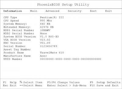
The System Information screen displays a summary of your computer hardware information.
NOTE: The screen above is a sample and may not reflect the actual data on your computer. The following table describes the information in this screen
The items in this screen are important and vital information about your computer. If you experience computer problems and need to contact technical support, this data helps our service personnel know more about your computer.
Parameter Description
CPU Type & Speed Describes the type of CPU installed in the system. System Memory Extended Memory HDD Serial Number Shows the serial number of the hard disk. System BIOS Version Shows the version number of the BIOS. VGA BIOS Version Shows the version number of the VGA display BIOS. KBC Version Serial Number Shows the serial number of the computer. Asset Tag Number Shows the asset tag number of the computer. Product Name Shows the product name of the computer. Manufacture Name Shows the manufacturer of the computer. UUID Number Shows the universally unique identifier of your computer.
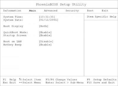
The Basic System Settings screen allows you to set the system date and time.
The following table describes the parameters in this screen
Parameter Description
Format
System Date Sets the system date. DDD MMM DD, YYYY (day-of-the-week month day, year) System Time Sets the system time. HH:MM:SS (hour:minute:second) Boot Display Sets the display device when the computer starts up. Both or Auto QuickBoot Mode QuickBoot allows your computer to skip certain tests at start-up to speed-up the boot process. Enable or Disable Startup Screen When enabled, it allows your computer to display the compute logo on boot-up. Enable or Disable Boot on LAN When enabled, it allows your computer to boot-up via the network Disabl or Enable Hotkey Beep Enables or disables a beep when a hotkey is pressed. Enable or Disable
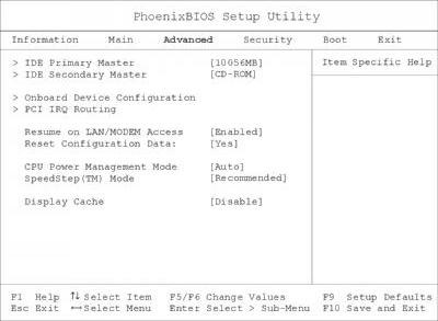
The Startup Configuration screen contains parameter values that define how your computer behaves on system startup.
The following table describes the parameters in this screen. Settings in boldface are the default and suggested parameter settings
Parameter
Description
IDE Primary Master Pres Enter to access the IDE Primary Master sub menu. IDE Secondary Master Pres Enter to access the IDE Secondary Maste sub-menu. Onboard Device Configuration Pres Enter to access the Onboard Device Configuration sub-menu. PCI IRQ Routing Pres Enter to access the PCI IRQ Routing sub menu.
Resume on LAN/ MODE Access When enabled, it allows your computer to resume normal operation when network or modem access is available.
Options
Enabled or Disabled
Reset Configuration Dat Select Yes to clear the Extended Syste Configuration Data. Yes or No
CPU Power Management Mode Set to auto to allow power management of the CPU. Auto or Disabled SpeedStep (TM) Mode Intel SpeedStep technology allows your computer t automatically adjust the CPU speed depending on the power source.
Recommended
Maximum Performance Battery Optimized Reversed Disabled
Display Cache When enabled, it allows VGA local memory control for the display cache. Disable or Enable
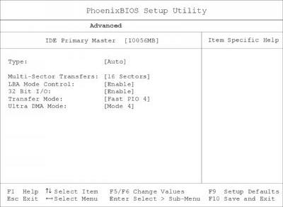
The IDE Primary Master sub-menu contains parameters related to the primary hard disk.
CAUTION: The parameters in this screen are for advanced users only. Typically, you do not need to change the values in this screen. The default setting of Auto optimizes all the settings for your hard disk.
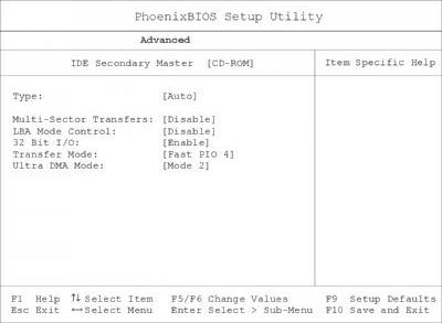
IDE Secondary Master
The IDE Secondary Master sub-menu contains parameters related to the AcerMedia bay drive.
CAUTION: The parameters in this screen are for advanced users only. Typically, you do not need to change the values in this screen. The default setting of Auto optimizes all the settings for your AcerMedia bay drive.
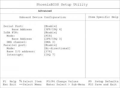
The Onboard Devices Configuration sub-menu contains parameters that are related to computer hardware.
CAUTION: The parameters in this screen are for advanced users only. Typically, you do not need to change the values in this screen because these values are already optimized.
The following table describes the parameters in this screen. Settings in boldface are the default and suggested parameter settings
Parameter
Description
Serial Port Enables or disables the serial port. When enabled, you can set the base I/O address and interrupt request (IRQ) of the serial port.
IrDA FIR Enables or disables the infrared port. When enabled, you can set the base I/O address, interrupt request (IRQ) and direct memory access (DMA) channel of the infrared port.
Parallel Port Enables or disables the parallel port. When enabled, you can set the base I/O address, interrupt request (IRQ) and operating mode of the parallel port. When the operating mode is set to ECP, you can set the DMA channel of the parallel port.
Options
Enable or Disable 3F8/ IRQ 4, 2F8/ IRQ 3, 3E8/ IRQ 4 or 2E8/ IRQ 3 Enable or Disable 2F8/ IRQ 3, 3E8/ IRQ 4, 2E8/ IRQ 3 or 3F8/ IRQ 4 DMA 3 or DMA 1 Enable or Disable Bi-directional, EPP, ECP or Output only 378, 278 or 3BC IRQ 7 or IRQ 5 DMA 1 or DMA 3
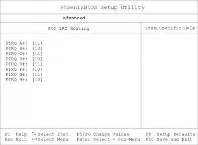
The PCI IRQ Routing sub-menu allows you to set IRQs for PCI devices.
CAUTION: The parameters in this screen are for advanced users only. Typically, you do not need to change the values in this screen because these values are already optimized.
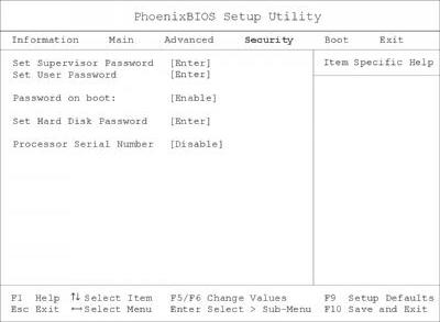
The System Security screen contains parameters that help safeguard and protect your computer from unauthorized use.
The following table describes the parameters in this screen. Settings in boldface are the default and suggested parameter settings
Setting a Password
Follow these steps: 1. Use the cursor up/ down keys to highlight a password parameter (Setup, Power-on or Hard Disk) and press the Enter key. The password box appears. 2. Type a password. The password may consist of up to seven characters (A-Z, a-z, 0-9). 3. Press Enter. Re-type the password to verify your first entry and press Enter. 4. After setting the password, the computer automatically sets the chosen password parameter to Present.
Parameter
Description
Set Supervisor Password When set, this password protects the BIOS Utility and Notebook Manager from unauthorized use. Press Enter to set this password. Set User Password When set, this password protects the computer from unauthorized use. Press Enter to set this password (requires the Supervisor Password to be set first). Password on boot When enabled, a password is requested when the syste boots up.
Set Primary Hard Disk Password
When set, this password protects your hard disk fro unauthorized access. Press Enter to set this password. Processor Serial Numbe The Pentium III processor includes a unique serial numbe which allows individual CPUs to be identified. You can turn off this feature by setting this parameter to Disabled.
Options
Enable or Disable
Disable or Enable
Removing a Password
Should you want to remove a password, do the following:
1. Use the cursor up/ down keys to highlight a password parameter (Setup, Power-on or Hard Disk) and press the Enter key. The password box appears. 2. Enter the current password and press Enter. 3. Press Enter twice without entering anything in the new field and confirm password fields to remove the existing password. NOTE: When you want to remove the Hard Disk (or 2nd Hard Disk) password, you are prompted for the current Hard Disk password before it is removed.
Changing a Password
To change a password, follow these steps: ! Remove the current password. See “Removing a Password” on page 36. ! Set a new password. See “Setting a Password” on page 36.
Boot Options
The Boot menu contains parameter values that determine in what order the bootable devices in your computer start-up.
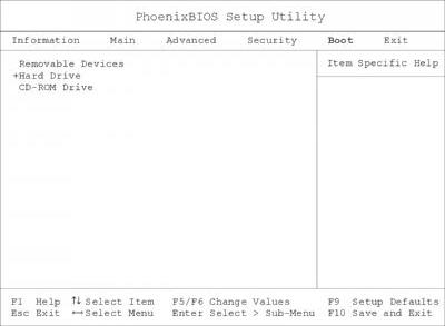
Setting the Boot Drive Sequence
Use the cursor up/ down keys to select a boot device, then press F5 or F6 to change its order. Items with a + sign can be further expanded.
This menu contains exit options.
The following table describes the parameters in this screen. Settings in boldface are the default and suggested parameter settings
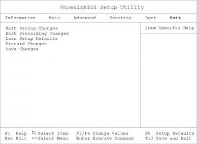
Parameter Description
Exit Saving Changes Saves your changes and exits the BIOS Utility. Exit Discarding Changes Discards your changes and exits the BIOS Utility. Load Setup Defaults Loads default settings for all setup parameters. Discard Changes Discards your changes. Save Changes Saves your changes.
The BIOS flash memory update is required for the following conditions: ! New versions of system programs ! New features or options Use the AFlash utility to update the system BIOS flash ROM. NOTE: Do not install memory-related drivers (XMS, EMS, DPMI) when you use AFlash. NOTE: This program contains a readme.txt file. This readme.txt file will introduce on how to use AFlash utility.
Executing Flash Program
IMPORTANT:If this diskette is not bootable, do the following actions before you use it: 1. Create a bootable disk. 2. Copy all AFlash files into this bootable diskette. 3. Put the bootable disk into TravelMate 610 series module, then reboot.
IMPORTANT:Never turn off the system power while Flash BIOS is programming. This will damage your system. 4. After Flash BIOS is done, reboot the system. NOTE: If there are any problems occurred during BIOS update, see for troubleshooting.
This utility diskette is for the Acer TravelMate 610 notebook machine. It provides the following functions: 1. Read Panel ID Setting 2. Write Panel ID Utility 3. Thermal and Fan Utility 4. Main Board Data Utility
To use this diskette, first boot from this diskette, then a “Microsoft Windows 98 Startup Menu” prompt you to choose the testing item. Follow the instructions on screen to proceed. NOTE: This program contains a readme.txt file. This readme.txt file will introduce each test utility and its functions.
IMPORTANT:If this diskette is not bootable, do the following actions before you use it: 1. Do system transfers. 2. Copy the following files to A:\.
HIMEM.SYS
RAMDRIVE.SYS
Read Panel ID Setting
This function will display registered information on the panel ID of Acer TravelMate 610 series. Then, Panel ID is set to EEPROM.
Write Panel ID Setting
This function will write a default LCD panel ID into EEPROM.
Thermal and Fan Utility
1. Set Thermal Setting This function will write the default value into EEPROM. 2. Read Thermal This function will display current system temperature and CPU temperature. First, the default of thermal range is displayed. For the system temperature, it ranges from 35 to 87 and for the CPU temperature, it is limited to 110. A CPU temperature below 110 is considered as normal temperature. 3. Test Fan The test item includes fan off test then it will proceed testing the fan for three different ranges of rpm. That is, over 4000 rpm, below 6000 rpm and finally, over 6000 rpm. If these tests succeed, the "PASS" message appears on the screen.Otherwise, an error message is displayed.
Main Board Data Utility
1. Default Setting The utility provides a strong function which can set all default settings to our EEPROM; such as Panel ID, Thermal Setting, Product Name and Product Manufacture. NOTE: Product Name should be written as default "TravelMate 610" because remote control of scrollbar(option item) will only identify the Product Name as TravelMate 610. 2. Read Mother board Data This provides the detailed information of mother board data. That includes Product Name, Manufacture Name, UUID, and serial number. 3. Write Manufacture name
It is allowed to input 4 bytes on the manufacture name and will revise the record into EEPROM automatically. 4. Write MBD UUID The MBD includes 32 bytes stored in EEPROM. There are two sub-functions: a. Create and write a new UUID This function is used when the original UUID is lost or damaged. b. Write UUID by user keyin This function is used when the original UUID is kept. The user can use "Read Main Board Data" function before to get it and have stored it. 5. Write MBD serial number This function allows to write 19 bytes MBD serial number by user keyin. The serial number can be found on the backside of the machine. a. Create and write a new UUID This function is used when the original UUID is lost or damaged. b. Write UUID by user keyin - This function is used when the original UUID is kept. User may use “Read Main Board Data” function first to keep the UUID.
IMPORTANT: 1The diagnostics program here that we used is called PQA (Product Quality Assurance) and is provided by Acer Headquarters. You can utilize it as a basic diagnostic tool. To get this program, either download it from http://csd.acer.com.tw or find it in the TravelMate 610 service CD kit. To better fit local service requirements, your regional office MAY have other diagnostic program. Please contact your regional offices or the responsible personnel/channel to provide you with further technical details. NOTE: This program contains a readme.txt file. This readme.txt file will introduce each test and its functions. This diagnostic program is designed to perform the following diagnostic tools for Acer TravelMate 610 notebook machine. It provides the following functions. 1. PQA Test 2. Audio Test 3. USB Test 4. Smart Card Test 5. IR Test 6. Exit To use this diskette, first boot from this diskette, then a “System Diagnostic Disk Menu” prompts you to choose the testing item. Follow the instructions on screen to proceed. IMPORTANT:If this diskette is not bootable, do the following actions before you use it: 1. Do system transfers. 2. Copy the following files to A:\
HIMEM.SYS
RAMDRIVE.SYS
CHOICE.COM
MSCDEX.EXE
PQA System Diagnostics
NOTE: This PQA diagnostics program will test Acer TravelMate 610 notebook series’ hardware peripherals. 1. When you select One Test, Test command (F2 key) will only work in the first-level menu (Item Test), if you are in sub-level menu, please press ESC to return to upper-level (Item Test) menu. 2. Use Space Bar to select/ deselect a testing item. 3. When testing is done, there will be a testing report, where you could find out whether the testing is successful or not.
Audio Test
The item consists of 3 tests: 1. Config & CD_Play Test Insert Audio CD (with Root_directory) into CD-ROM. Press "a" once to stop the CD from playing and then press any key to exit this test. 2. Loopback Test: You have to attach "loop_line" into line-in and line-out port on the rear panel of TravelMate 610 for this test. You will see a "PASS" message if test is successful. 3. Built_in Micro_phone test: Make any sound after pressing enter. Then the machine will start to record the sound you made for about five second, and play it. Please take out "loop_line" before executing the test.
USB Test
This function will test USB Connect/Disconnect of TravelMate 610 notebook series. UHCI/OHCI test utility: 1. Please prepare a USB device such as USB mouse, USB keyboard, USB floppy diskette or USB modem, and leave the USB ports disconnected. NOTE: The diagnostic program will not be interrupted by disconnecting the USB diskette. 2. The program will dynamically detect the incoming device for 2 USB ports. Plug the USB connector on the first USB port, then un-plug it (connect at one time and disconnect at another time). To continue testing the second USB port, repeat the connect/disconnect procedure. The testing program will show an account of connection/disconnection if every step is doing right. Consequently, a "PASS" message appears on the screen, otherwise, it displays "FAIL".
Smart Card Test
Insert Smart Card into the socket of the left panel. If it is doing well, the message "PASSED!!!" will be shown on the screen.
Infrared Ray (IR) Test
This function will test Infrared Ray of Acer TravelMate 610 series. Following are the steps: 1. Please prepare 2 machines. Choose "Test_program for Server" for one of the machines and choose "1" for Baud_Rate. 2. Choose "Test_program for Client" for the other machine. 3. Make the IR ports of the 2 machines close, then, after the detection between the two machines, the pass or fail message will appear on the screen.
Running PQA Diagnostics Program
PQA Vx_x xx-xx-xx
Diag Result SysInfo Option Exit
Press →← →← →← →← to move around the main menu. Press Enter to enable the selected option. The main options are Diag, Result, SysInfo, Option and Exit. The Diag option lets you select testing items and times. The following screen appears when you select Diag from the main menu.
PQA Vx_x xx-xx-xx
Diag Result SysInfo Option Exit Diag
ONE TEST MULTI TEST FULL TEST QUICK TEST
One Test performs a single test and Manual checks the selected test items in sequence. Multi Test performs multiple tests of the selected items and check the selected test items in sequence. Full Test performs all test items in detail for your system. Quick Test performs all test items quickly for your system. The screen below appears if you select Multi Test.
PQA Vx_x xx-xx-xx PQA Vx_x xx-xx-xx
Diag Diag Result Result SysInfo SysInfo Option Option Exit Exit
Diag One TEST Multi TEST Diag ONE TEST MULTI TEST FULL TEST
QUICK TEST
TEST COUNT VALUE (1...9999) 1
Specify the desired number of tests and press Enter. After you specify the number of tests to perform, the screen shows a list of test items (see below).
PQA Vx_x xx-xx-xx
DiagDiag Result SysInfo Option Exit
MANUAL TESTTest Items AUTO TEST[ ] System Board [ ] Memory [ ] Keyboard [ ] Video [ ] Parallel Port [ ] Serial Port [ ] Diskette Drive [ ] Hard Disk [ ] CD-ROM [ ] Coprocessor [ ] Pointing Dev. [ ] Cache SPACE: mark/unmark selecting item ESC : return to upper menu
F2 : test the marked item(s) ENTER: open sub-item’s menu Test Times = 1
Move the highlight bar from one item to another. Press Space to enable or disable the item. Press Enter to view the available options of each selected item. Press Esc to close the submenu. The right corner screen information gives you the available function keys and the specified test number. ! Space: Enables/disables the item ! ESC: Exits the program ! F1: Help ! F2: Tests the selected item(s) ! Enter: Opens the available options ! Test Times: Indicates the number of tests to perform. NOTE: The F1 and F2 keys function only after you finish configuring the Test option. NOTE: When any errors are detected by diagnostic program, refer to “Index of PQA Diagnostic Error Code, Message” on page 87 for troubleshooting.