10 minute read
Chapter 2 System Utilities


System Utilities
BIOS Setup Utility
The BIOS Setup Utility is a hardware configuration program built into your computer’s BIOS (Basic Input/ Output System). Your computer is already properly configured and optimized, and you do not need to run this utility. However, if you encounter configuration problems, you may need to run Setup. Please also refer to Chapter 4 Troubleshooting when problem arises. To activate the BIOS Utility, press m during POST (when “Press <F2> to enter Setup” message is prompted on the bottom of screen). Press m to enter setup. Press <F12> during POST to enter multi-boot menu. In this menu, user can change boot device without entering BIOS SETUP Utility.
There are six menu options: Information, Main, Advanced, Security, Boot, and Exit. Follow these instructions: To choose a menu, use the cursor left/right keys (zx). To choose a parameter, use the cursor up/down keys ( wy). To change the value of a parameter, press por q. A plus sign (+) indicates the item has sub-items. Press e to expand this item. Press ^ while you are in any of the menu options to go to the Exit menu. In any menu, you can load default settings by pressing t. You can also press u to save any changes made and exit the BIOS Setup Utility.
NOTE: You can change the value of a parameter if it is enclosed in square brackets. Navigation keys for a particular menu are shown on the bottom of the screen. Help for parameters are found in the Item Specific Help part of the screen. Read this carefully when making changes to parameter values.
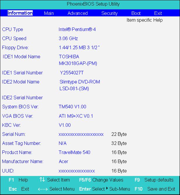
This menu provides you the information of the system.
Parameter Description Floppy Disk Drive Shows floppy drive type informaiton. The Floppy Drive status is auto detected by system. 1.44MB, 3 1 ⁄ 2 ” If there exists floppy drive. Not installed If there is no floppy drive. IDE1 Model Name Shows the Model name of HDD installed on Primary IDE master. The hard disk model name is automatically detected by the system. If there is no hard disk present or unknown type, “None” should be shown on this field. IDE1 Serial # This field display the Serial number of HDD installed on Primary IDE master. If no Hard disk or other devices are installed on Primary IDE master, then it will display a blank line. IDE2 Model Name This item will show the Model name of device installed on Secondary IDE master. The hard disk or CD-ROM model name is automatically detected by the system. If there is no hard disk or CD-ROM present or unknown type, “None” should be shown on this field. IDE2 Serial # This item will show the Serial number of HDD installed on Secondary IDE master. If no hard disk or other devices are installed on Primary IDE master, then it will display a blank line. Serial Number This field displays the serial number of this unit. UUID Number UUID=32bytes
The Main screen displays a summary of your computer hardware information, and also includes basic setup parameters. It allows the user to specify standard IBM PC AT system parameters.
NOTE: The screen above is for reference only. Actual values may differ.
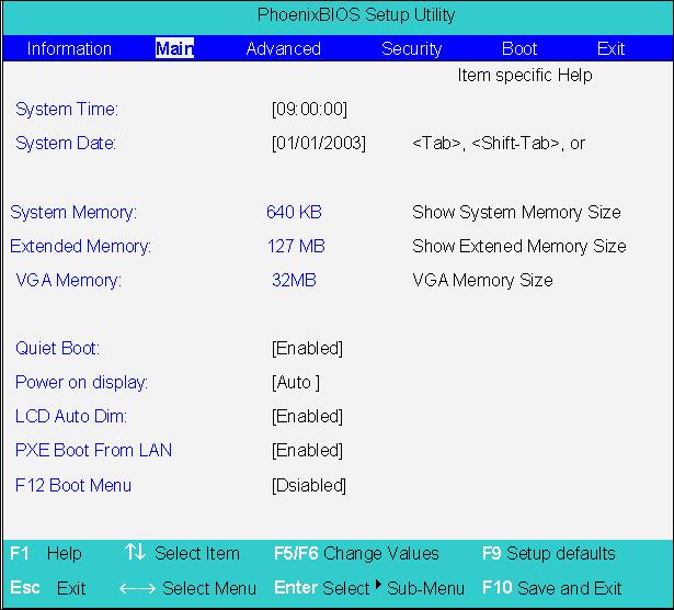
Parameter Description Format/Option System Time Sets the system time. Format: HH:MM:SS (hour:minute:second) System Time System Date Sets the system date. Format MM/DD/YYYY (month/day/ year) System Date
System Memory This field reports the memory size of the system. Memory size is fixed to 640MB Extended Memory This field reports the memory size of the extended memory in the system. Extended Memory size=Total memory size-1MB VGA Memory Shows the VGA memory size. The default value is set to 16MB Option:16/32MB
Quiet Boot Determines if Customer Logo will be displayed or not; shows Summary Screen is disabled or enabled. Enabled: Customer Logo is displayed, and Summary Screen is disabled. Disabled: Customer Logo is not displayed, and Summary Screen is enabled. Power on display Auto: During power process, the system will detect if any display device is connected on external video port. If any external display device is connected, the power on display will be in CRT (or projector) only mode. Otherwise it will be in LCD only mode. Both: Simultaneously enable both the integrated LCD screen and the system’s external video port (for an external CRT or projector). LCD Auto Dim Determines if the system will automatically dim the LCD brightness in order to save power when AC is not present.
PXE (Preboot Execution Environment) Boot From LAN Indicates that whether the notebook can boot from LAN or not. Option: Enabled or Disabled
Option: Auto or Both
Option: Enabled or Disabled
Option: Enabled or Disabled
F12 Boot Menu Determines if the OEM POST screen will have “Press <F12> Change Boot Device” or not during user’s quite boot. Option: Enabled or Disabled
NOTE: The sub-items under each device will not be shown if the device control is set to disable or auto. This is because the user is not allowed to control the settings in these cases.
The Advanced menu screen contains parameters involving your hardware devices. It also provides advanced settings of the system.
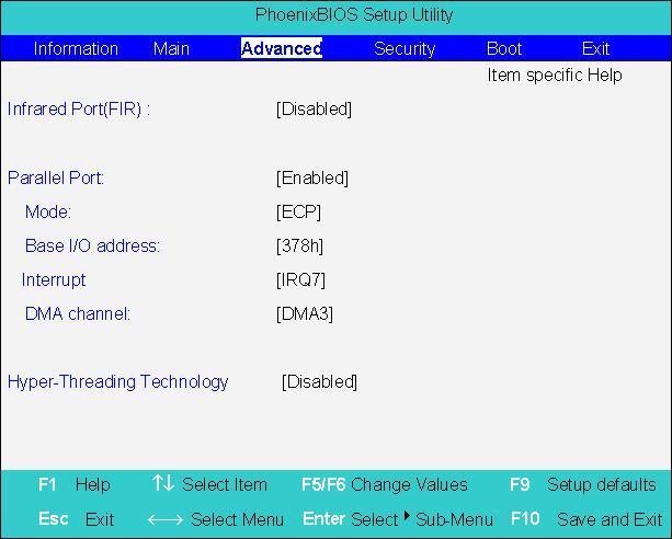
Parameter Description Options Infrared Port (FIR) Enables, disables or auto detects the infrared port. Enabled/Disabled/Auto Base I/O address/IRQ Sets I/O address of the infrared port. 3F8h/IRQ4; 2F8h/IRQ3; 3E8h/ IRQ4; 2E8h/IRQ3 DMA Sets a DMA channel of the infrared port. DMA 1/DMA 3 Parallel Port Enables, disables or auto detects the parallel port. Enabled/Disabled/Auto Mode Sets the operation mode of the parallel port. ECP, EPP, Output only or Bidirectional Base I/O address Sets the I/O address of the parallel port. This parameter is enabled only if Mode is set to ECP or Bi-directional. This parameter is enabled only if Mode is set to ECP. 378/278/3BC
Interrupt Sets the interrupt request of the parallel port. IRQ7/IRQ5 DMA channel Sets a DMA channel for the printer to operate in ECP mode. This parameter is enabled only if Mode is set to ECP. DMA3/DMA1 Hyperthreading technology This only support CPU 3.06G or above. BIOS should automatically hide this selection when detecting the CPU frequency is below 3.06G or the CPU does not support Hyperthreading technology. Even if Hyperthreading technology does not support on certain system configuration, this value is set “disabled” as default value. Enabled/Disabled
The Security screen contains parameters that help safeguard and protect your computer from unauthorized use.
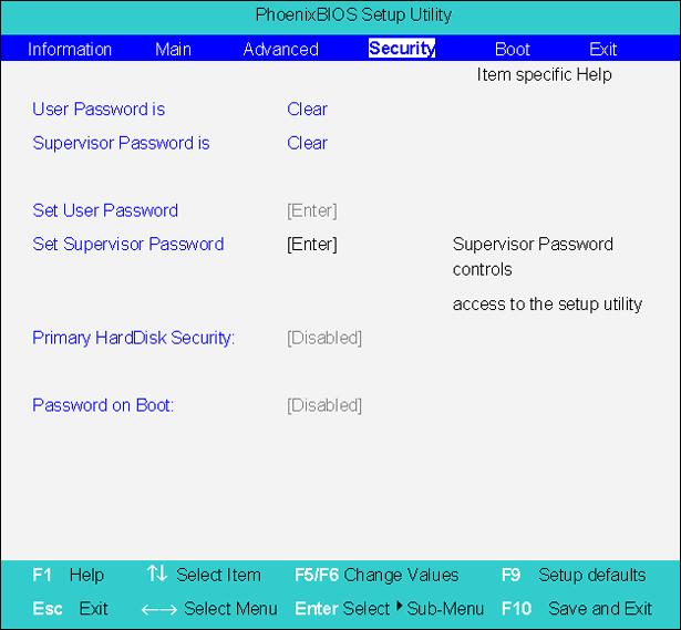
Parameter Description
Option User Password is Shows the setting of the uer password. Clear or Set Supervisor Password is Shows the setting of the Supervisor password Clear or Set Set User Password Press Enter to set the user password. When set, this password protects the BIOS Setup Utility from unauthorized access. Set Supervisor Password Press Enter to set the supervisor password. When set, this password protects the BIOS Setup Utility from unauthorized access. Primary Harddisk Security This feature is available to user when Supervisor password is set. Password can be written on HDD only when Supervisor password or user password is set and password on HDD is set to enabled. Supervisor Password is written to HDD only when Supervisor password is being set. User password is written to HDD when both passwords are set. When both Supervisor and user password are present, both passwords can unlock the HDD. Disabled or Enabled Password on Boot Defines whether a password is required or not while the events defined in this group happened. The following sub-options are all requires the Supervisor password for changes and should be grayed out if the user password was used to enter setup. Disabled or Enabled
NOTE: When you are prompted to enter a password, you have three tries before the system halts. Don’t forget your password. If you forget your password, you may have to return your notebook computer to your dealer to reset it.
Setting a Password
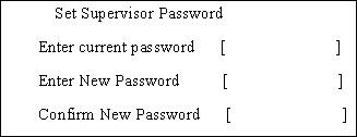
Follow these steps as you set the user or the supervisor password: 1. Use the w andy keys to highlight the Set Supervisor Password parameter and press the e key. The Set Supervisor Password box appears:

2. Type a password in the “Enter New Password” field. The password length can not exceeds 8 alphanumeric characters (A-Z, a-z, 0-9, not case sensitive). Retype the password in the “Confirm New
Password” field.
IMPORTANT:Be very careful when typing your password because the characters do not appear on the screen. 3. Press e. After setting the password, the computer sets the User Password parameter to “Set”. 4. If desired, you can opt to enable the Password on boot parameter. 5. When you are done, press u to save the changes and exit the BIOS Setup Utility.
Removing a Password
2. Type the current password in the Enter Current Password field and press e. 3. Press e twice without typing anything in the Enter New Password and Confirm New Password fields.
The computer then sets the Supervisor Password parameter to “Clear”. 4. When you have changed the settings, press u to save the changes and exit the BIOS Setup Utility.
2. Type the current password in the Enter Current Password field and press e. 3. Type a password in the Enter New Password field. Retype the password in the Confirm New Password field. 4. Press e. After setting the password, the computer sets the User Password parameter to “Set”. 5. If desired, you can enable the Password on boot parameter. 6. When you are done, press u to save the changes and exit the BIOS Setup Utility.
If the verification is OK, the screen will display as following.

The password setting is complete after the user presses u.
If the current password entered does not match the actual current password, the screen will show you the Setup Warning.

If the new password and confirm new password strings do not match, the screen will display the following message.

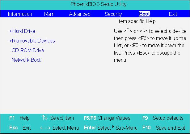
This menu allows the user to decide the order of boot devices to load the operating system. Bootable devices includes the distette drive in module bay, the onboard hard disk drive and the CD-ROM in module bay.
The Exit screen contains parameters that help safeguard and protect your computer from unauthorized use.
The table below describes the parameters in this screen.
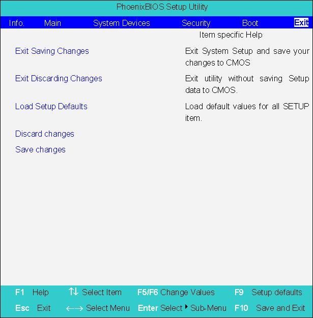
Parameter Description Exit Saving Changes Exit System Setup and save your changes to CMOS. Exit Discarding Changes Exit utility without saving setup data to CMOS. Load Setup Default Load default values for all SETUP item. Discard Changes Load previous values from CMOS for all SETUP items. Save Changes Save Setup Data to CMOS.
The BIOS flash memory update is required for the following conditions: New versions of system programs New features or options Restore a BIOS when it becomes corrupted. Use the Phlash utility to update the system BIOS flash ROM. NOTE: If you do not have a crisis recovery diskette at hand, then you should create a Crisis Recovery Diskette before you use the Phlash utility. NOTE: Do not install memory-related drivers (XMS, EMS, DPMI) when you use the Phlash. NOTE: Please use the AC adaptor power supply when you run the Phlash utility. If the battery pack does not contain enough power to finish BIOS flash, you may not boot the system because the BIOS is not completely loaded. Fellow the steps below to run the Phlash. 1. Prepare a bootable diskette. 2. Copy the Phlash utilities to the bootable diskette. 3. Then boot the system from the bootable diskette. The Phlash utility has auto-execution function.