15 minute read
Chapter 2 System Utilities


System Utilities
BIOS Setup Utility
The BIOS Setup Utility is a hardware configuration program built into your computer’s BIOS (Basic Input/ Output System). Your computer is already properly configured and optimized, and you do not need to run this utility. However, if you encounter configuration problems, you may need to run Setup. Please also refer to Chapter 4 Troubleshooting when problem arises. To activate the BIOS Utility, press m during POST (when “Press <F2> to enter Setup” message is prompted on the bottom of screen). Press F12 to change boot order.
Navigating the BIOS Utility
There are six menu options: Info. Main, System Devices, Security, Boot and Exit. Follow these instructions: To choose a menu, use the cursor left/right keys (zx). To choose a parameter, use the cursor up/down keys ( wy).
To change the value of a parameter, press p or q. Press ^ while you are in any of the menu options to go to the Exit menu. In any menu, you can load default settings by pressing t. You can also press u to save any changes made and exit the BIOS Setup Utility.
NOTE: You can change the value of a parameter if it is enclosed in square brackets. Navigation keys for a particular menu are shown on the bottom of the screen. Help for parameters are found in the Item Specific Help part of the screen. Read this carefully when making changes to parameter values.
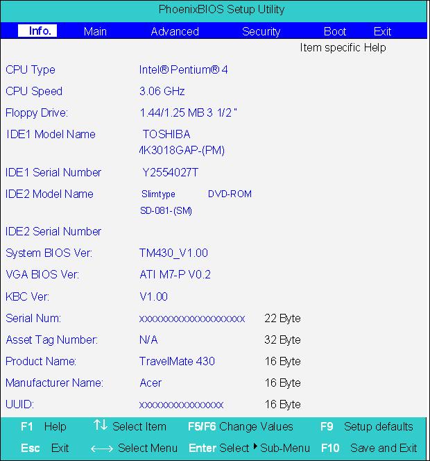
This menu provides you the information of the system.
Parameter Description
Floppy Drive The Floppy Drive status is auto detected by the system. The information page would display “1.44MB, 3 1/2 if floppy drive exists; it would display “Not installed” if floppy drive does not exist. IDE1 Model Name Shows the Model name of HDD installed on Primary IDE master. The system will auto detect the hard disk model name. “None” means the hard disk drive is not existing or unknown type. IDE1 Serial Number This item displays the Model Name of HDD installed on Primary IDE master. If no hard disk or other devices are installed on Primary IDE master, this item will display a blank line. IDE2 Model Name Displays the Model Name of Device installed on Secondary IDE master. The hard disk or CD-ROM model is automatically detected by the system. If the hard disk drive or CD-ROM is not existing or unknown type, this field would display “None”. IDE2 Serial Number This field shows the Serial Number of HDD installed on Secondary IDE master. If no hard disk drive or other devices are installed on Primary IDE master, it will display a blank line. System BIOS Version Displays system BIOS version VGA BIOS Version Displays VGA BIOS version Serial Number Displays the serial number of the unit.
Parameter
Description
UUID Number UUID=16bytes. This will be visible only when there is an internal LAN device present. System Memory This field reports the memory size of system base memory. The size is fixed to 640KB.
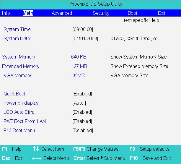
The Main screen displays a summary of your computer hardware information, and also includes basic setup parameters. It allows the user to specify standard IBM PC AT system parameters.
NOTE: The screen above is for reference only. Actual values may differ.
Parameter Description Format/Option
System Time Sets the system time. Format: HH:MM:SS (hour:minute:second) System Time System Date Sets the system date. Format MM/DD/YYYY (month/day/ year) System Date
System Memory This field reports the memory size of system base memory. The size is fixed to 640KB.
Extended Memory This field reports the memory size of the extended memory in the system. Extended Memory size=Total memory size-1MB VGA Memory VGA Memory size=16MB Quiet Boot Control whether Customer Logo and Summary Screen are displayed or not. Option: Enabled or Disabled
Power on Display Auto: During power on process, the system will detect if any display device is connected on external video port. If any external display device is connected, the power on display will be in CRT (or projector) only mode. Otherwise the system will be in LCD only mode. Both: Simultaneously enable both the integrated LCD screen and the system’s external video port (for an external CRT or projector). Option: Auto or Both
LCD Auto Dim Enabled: LCD brightness will automatically lower to save more power when AC is not present. Disabled: LCD brightness will NOT automatically lower to save more power when AC is not present. Option: Enabled or Disabled
F12 Boot Menu This field decides whether the OEM POST screen will have the following message: “Press <F12> Change Boot Device” or not during user’s quiet boot. Option: Enabled or Disabled
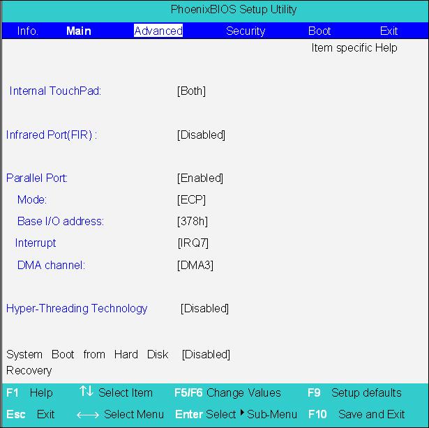
NOTE: The sub-items under each device will not be shown if the device control is set to disable or auto. This is because the user is not allowed to control the settings in these cases.
The System Devices screen contains parameters involving your hardware devices. It also provides advanced settings of the system.
Parameter Description Options
Internal TouchPad Determines whether or not to disable the internal touchpad of a PS/2 pointing device is connected. Infrared Port (FIR) Sets the interrupt request of the serial port. Please set the parameter to “Enabled” if you need to use FIR under Windows operation system. Both or Auto
Disabled/ Enabled/ Auto
Base I/O address/IRQ Sets the I/O address of the Infrared port. 3F8h/IRQ4; 2F8h/IRQ3; 2E8h/IRQ3 DMA Sets a DMA channel for the printer to operate in disabled mode. DMA1/ DMA3 Parallel Port Enables, disables or auto detects the parallel port. Enabled/Disabled/Auto Mode Sets the operation mode of the parallel port. ECP, EPP, Normal or Bi-directional Base I/O address/ Sets the I/O address of the parallel port. This parameter is enabled only if Mode is set to ECP or Bi-directional. 378h, 278h or 3BCh Interrupt Sets the interrupt request of the parallel port. IRQ 7 or IRQ5 DMA Channel Sets a DMA channel for the printer to operate in ECP mode. This parameter is enabled only if Mode is set to ECP. DMA3 or DMA1
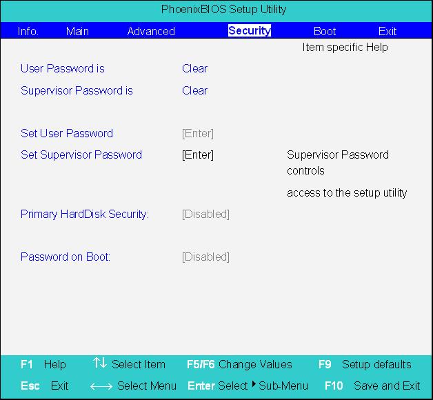
The Security screen contains parameters that help safeguard and protect your computer from unauthorized use.
Parameter Description
Option
User Password is Shows the setting of the user password. Clear or Set Supervisor Password is Shows the setting of the Supervisor password Clear or Set Set User Password Press Enter to set the user password. When set, this password protects the BIOS Setup Utility from unauthorized access. Set Supervisor Password Press Enter to set the administrator password. When set, this password protects the BIOS Setup Utility from unauthorized access. Primary Harddisk Security This feature is available to user when Supervisor password is set. Password can be written on HDD only when Supervisor password or user password is set and password on HDD is set to enabled. Supervisor Password is written to HDD only when Supervisor password is being set. User password is written to HDD when both passwords are set. When both Supervisor and user password are present, both passwords can unlock the HDD. Disabled or Enabled Password on Boot Defines whether a password is required or not while the events defined in this group happened. The following sub-options are all requires the Supervisor password for changes and should be grayed out if the user password was used to enter setup. Disabled or Enabled
NOTE: When you are prompted to enter a password, you have three tries before the system halts. Don’t forget your password. If you forget your password, you may have to return your notebook computer to your dealer to reset it.
Setting a Password
Follow these steps as you set the user or the administrator password: 1. Use the w andy keys to highlight the Set Administrator Password parameter and press the e key. The Set Administrator Password box appears:
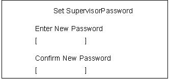
2. Type a password in the Enter new password field. The password length can not exceeds 8 alphanumeric characters (A-Z, a-z, 0-9, not case sensitive). Retype the password in the Confirm new password field.
IMPORTANT:Be very careful when typing your password because the characters do not appear on the screen. 3. Press e. After setting the password, the computer sets the User Password parameter to “Set”. 4. If desired, you can opt to enable the Password on boot parameter. 5. When you are done, press u to save the changes and exit the BIOS Setup Utility.
Removing a Password

2. Type the current password in the Enter Current Password field and press e. 3. Press e twice without typing anything in the Enter New Password and Confirm New Password fields.
The computer then sets the Administrator Password parameter to “Clear”. 4. When you have changed the settings, press u to save the changes and exit the BIOS Setup Utility.
Changing a Password
2. Type the current password in the Enter Current Password field and press e. 3. Type a password in the Enter New Password field. Retype the password in the Confirm New Password field. 4. Press e. After setting the password, the computer sets the User Password parameter to “Set”. 5. If desired, you can enable the Password on boot parameter. 6. When you are done, press u to save the changes and exit the BIOS Setup Utility.

The password setting is complete after the user presses u. If the current password entered does not match the actual current password, the screen will show you the Setup Warning.

If the new password and confirm new password strings do not match, the screen will display the following message.

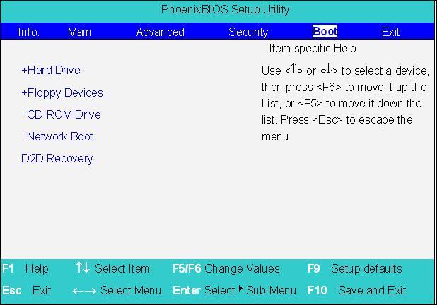
This menu allows the user to decide the order of boot devices to load the operating system. Bootable devices includes the distette drive in module bay, the onboard hard disk drive and the CD-ROM in module bay.
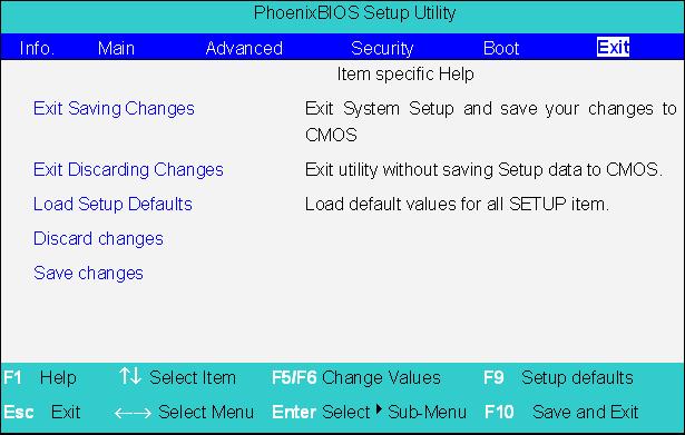
The Exit screen contains parameters that help safeguard and protect your computer from unauthorized use.
The table below describes the parameters in this screen.
Parameter Description
Exit Saving Changes Allows the user to save changes to CMOS and reboot the system. Exit Discarding Changes Allows the user Discards changes made and exits System Setup. Load Setup Default Loads default settings for all parameters (same as t ). Discard Changes Allows the user to discard previous changes in CMOS Setup. Save Changes Allows the user to save current changes in CMOS Setup.
The BIOS flash memory update is required for the following conditions: New versions of system programs New features or options Restore a BIOS when it becomes corrupted. Use the Flash utility to update the system BIOS flash ROM. NOTE: If you do not have a crisis recovery diskette at hand, then you should create a Crisis Recovery Diskette before you use the Flash utility. NOTE: Do not install memory-related drivers (XMS, EMS, DPMI) when you use the Flash utilities. NOTE: Please use the AC adaptor power supply when you run the Flash utility. If the battery pack does not contain enough power to finish BIOS flash, you may not boot the system because the BIOS is not completely loaded. Fellow the steps below to run the Flash. 1. Prepare a bootable diskette. 2. Copy the Flash utilities to the bootable diskette. 3. Then boot the system from the bootable diskette. The Flash utility has auto-execution function.
System Diagnostic Diskette
This diagnostic diskette is for the Acer TravelMate 430 series notebook machine. You can find the utility in Service CD kit. It provides the following functions: 1. RTC Function Test 2. PIO Loop Back Test 3. CD ROM Function Test 4. Touchpad and USB Mouse Test 5. Video Model (R.G.B.) Test 6. Internal Keyboard Test 7. Num/Caps/Scroll Key Lock Test 8. Battery (Charge/Discharge) Test 9. Audio Test 10. Audio CD Play Function Test 11. Lid Switch Function Test 12. Easy Button Function Test 13. FAN Test 14. CRT Output Function Test
To use the diagnostic programs, and system utilities, please boot the system from this service CD. The diagnostic programs contain autorun function under DOS. Please select the item you want to test under DOS mode according to the menu.
IMPORTANT: 1The diagnostics program we use for TravelMate 430 series is not exactly the same as PQA (Product Quality Assurance), the diagnostic program we used to employ in other model. The system diagnostic utilities is provided by Acer Headquarters. You can utilize it as a basic diagnostic tool. To get this program, find it in the TravelMate 430 series service CD kit. To better fit local service
requirements, your regional office MAY have other diagnostic program. Please contact your regional offices or the responsible personnel/channel to provide you with further technical details. NOTE: For ASSY Function Test Procedure, please prepare the following items for system components test: PC (with FIR port), 1394 HDD, PS2 mouse, PS2 Ext-KB, CRT monitor, USB mouse, CD-ROM, DVDROM disc (with data and audio track), external speaker, internal CD-ROM module, internal DVD-ROM module, SD card, MS card, AC adapter (90W), TV. NOTE: As running the testing utility, please do use the right AC adapter (90W, 19V/4740mA). If you use AC adapter lower than 90W, it will damage notebook computer power circuit material.
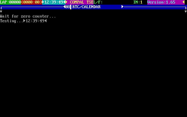
1. RTC Function Test Run the RTC Function Test program.
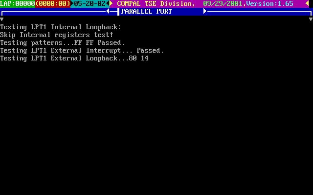
2. PIO Loop Back Test Insert PIO loopback fixture to main board PIO connect then run the testing program.
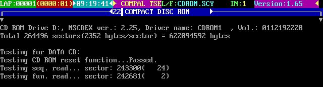
3. CD-ROM Function Test Insert a data CD to CD-ROM drive. Then check the CD-ROM drive function with CD-ROM Function Test.
4. Touchpad and USB Mouse Test This utility can test touchpad and USB ports. The three USB ports locate on the right panel. Please insert a USB mouse to USB port 1, port 2 and port 3. As you run the testing utility, please test port 1 and port 2 first. Move the mouse and click the left and the right button to test its functions. After USB port 1 and port two have been checked, please insert the mouse to the third USB port for testing. Move the mouse and click the right and the left button to see if it works fine.
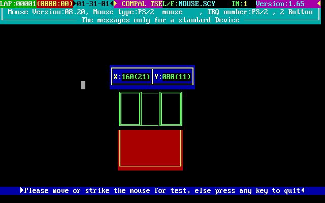
USB Port 1 USB Port 2 USB Port 3 5. Video Model (R. G. B.) Test Use the utility to test LCD color(red, green, blue, white, black) mode. Please press “Enter” key to continue each color display.

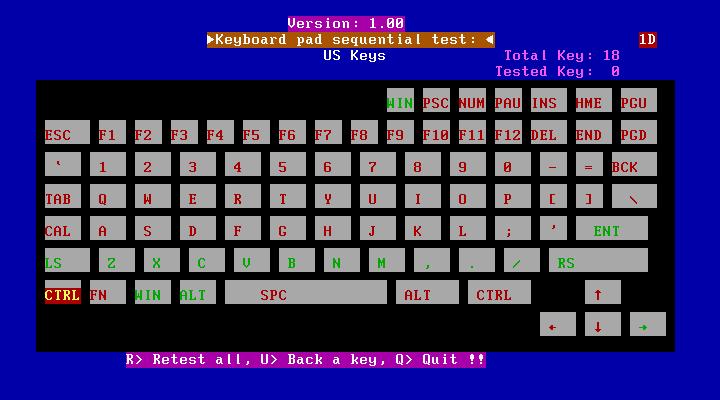
6. Internal Keyboard Test
Run the Internal Keyboard Test. Press the key one by one to see if it functions well or not. If suspect a certain key has problem, please press “B” key to test the key again.
7. Num/Caps/Scroll Key Lock Test Press the FN+Num/Caps key. Then check if the FN+Num/Caps media LED is emitting or not.
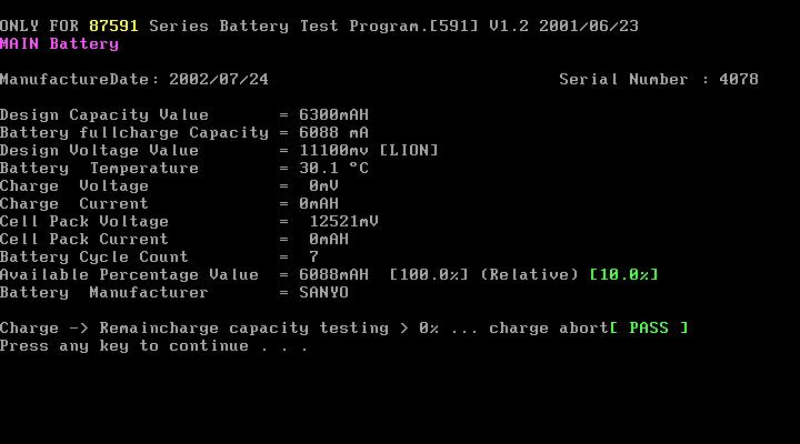
8. Battery (Charge/Discharge) Test Use Battery Test to check AC adapter function and charging LED. Please plug in the AC adapter before you run the testing utility. If the battery capacity is more than 95%, it will alway pass the test. IMPORTANT:As running the testing utility, please do use the right AC adapter (90W, 19V/4740mA). If you use AC adapter lower than 90W, it will damage notebook computer power circuit material.
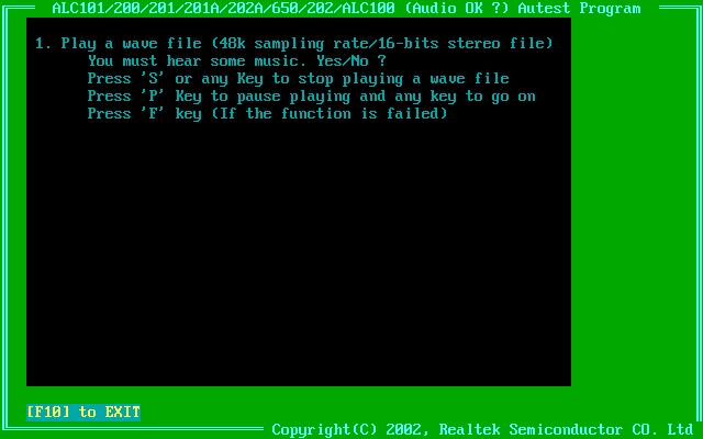
9. Audio Test Use this utility to test audio function. Please test internal speakers first. Then insert the external speakers to speaker phone jack and see if it functions normally. Listen to the sound emitting from the left and the right speakers (both internal and external).

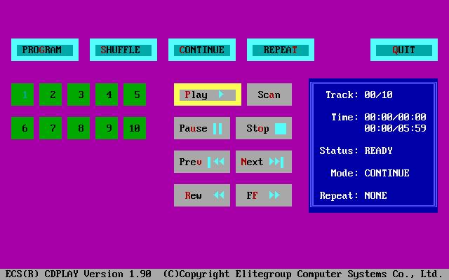
10. Audio CD Play Function Test Put a music compact disc in CD-ROM drive. Click “Play” button that display on the LCD/or external CRT monitor to play the music disc. Then click on other function keys to test its functions. Click on “QUIT” to exit the testing.
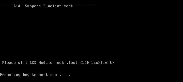
11. Lid Switch Function Test Please use the utility to test the Lid Switch Functioin. Close the LCD to press “Lid switch” for testing. Then check if the LCD backlight is on or off.
12. Easy Button Function Test Please press the launch keys and audio controls respectively to see if they work normally. Launch keys locate on the middle cover; audio controls locate on the front panel. Once you press any launch key or audio control, the button displaying on the LCD/CRT monitor will disappear at the same time.
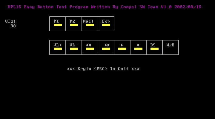
NOTE: Please also note the FIR LED colors. It emits orange for Wireless mode; green for bluetooth mode. If FIR LED does not light up, it means there is no wireless function.
13. FAN Test Run FAN test program to check if fan wire and fan function works normally.

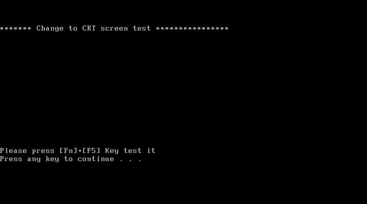
14. CRT Output Function Test
Run CRT output fucntion test to see if CRT displays well. Please plug in CRT cable to monitor connectorFAN test program to check if fan wire and fan function works normally. Press “Fn+F5” to switch to CRT monitor and LCD. This utility mainly checks if you can be switch to LCD and CRT monitor on this notebook computer.