1 minute read
Chapter 5 Jumper and Connector Locations


Jumper and Connector Locations
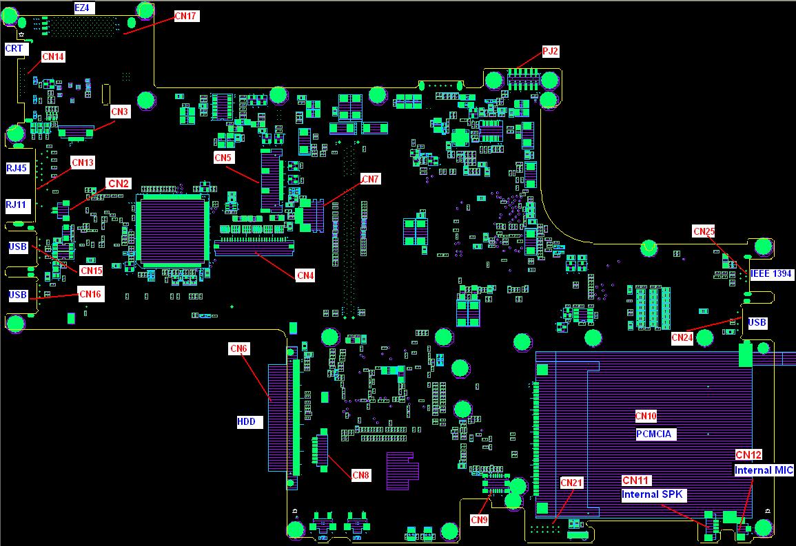
Top View
Number
CN2 Modem cable
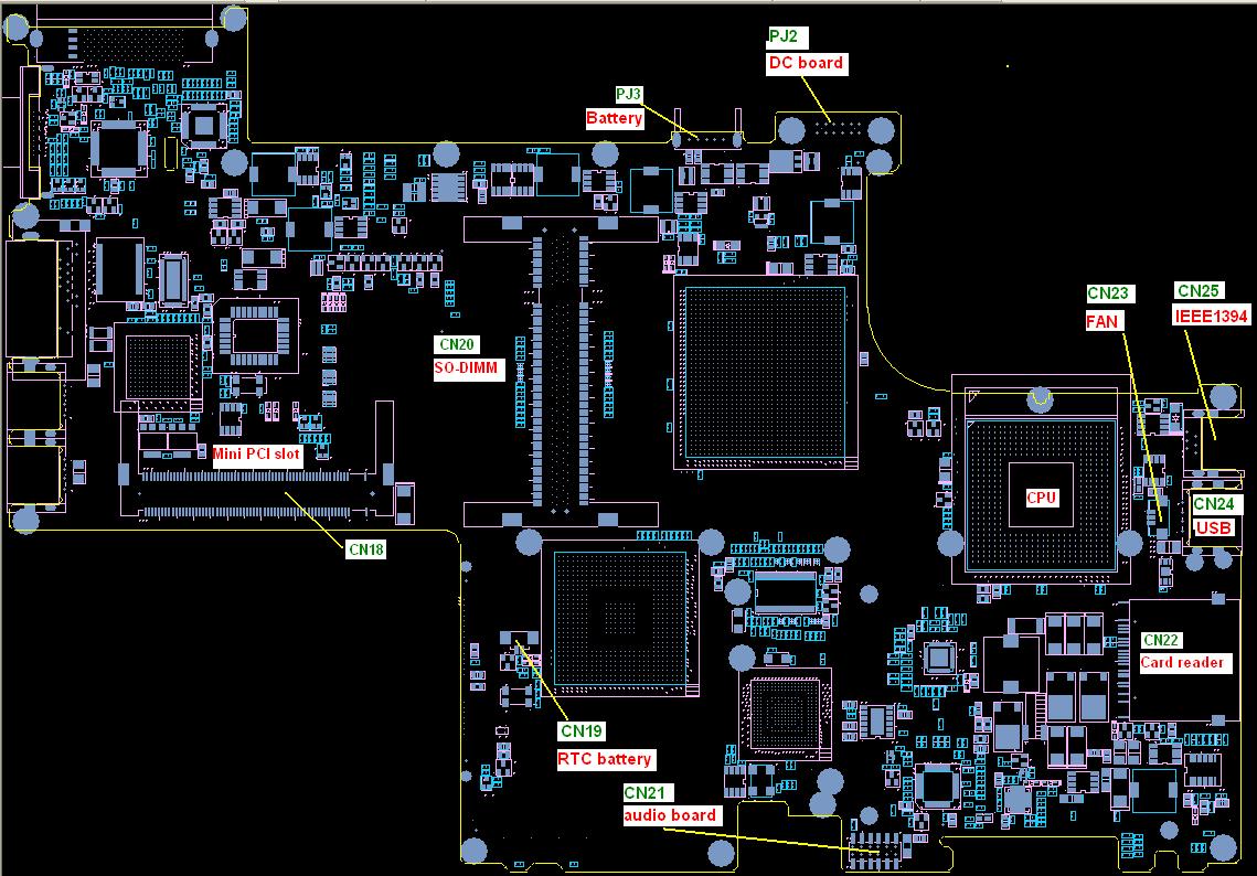
CN3 Switch board CN4 Internal keyboard CN5 LCD CN6 HDD CN7 Touchpad board CN8 Bluetooth module CN9 MDC modem CN10 PC card CN11 Internal speaker CN12 Internal MIC CN13 RJ11/RJ45 CN14 CRT CN15 USB CN16 USB CN17 EZ4 CN18 Mini PCI slot CN19 RTC battery CN20 DDR2 slot CN21 Audio board CN22 Card reader CN23 Fan CN24 USB CN25 1394 PJ2 DC board PJ3 Battery Item
1. Disassemble the base chassis. 2. Remove CMOS battery. (CN19 on the bottom of MB) 3. Discharge Capacitor. (C403 on the bottom of MB) 4. Please refer to following image for location.