22 minute read
Chapter 3 Machine Disassembly and Replacement


Machine Disassembly and Replacement
This chapter contains step-by-step procedures on how to disassemble the notebook computer for maintenance and troubleshooting. To disassemble the computer, you need the following tools: Wrist grounding strap and conductive mat for preventing electrostatic discharge Flat-bladed screw driver Phillips screw driver Tweezers Plastic Flat-bladed screw driver Hexed Screw Driver NOTE: The screws for the different components vary in size. During the disassembly process, group the screws with the corresponding components to avoid mismatch when putting back the components. NOTE: This chapter has been revised from previous model (TravelMate 240/250). Please refer to the disassembling procedures instead of the images. Some of the images below contain the parts used in TravelMate 240/250, but not in Extensa 2000/2500.
Before You Begin
Before proceeding with the disassembly procedure, make sure that you do the following: 1. Turn off the power to the system and all peripherals. 2. Unplug the AC adapter and all power and signal cables from the system.
The flowchart on the succeeding page gives you a graphic representation on the entire disassembly sequence and instructs you on the components that need to be removed during servicing. For example, if you want to remove the main board, you must first remove the keyboard, then disassemble the inside assembly frame in that order.
Start
Battery
HDD Module
G*2
HDD HDD Holder *2
DIMM Cover
Memory *2
Modem Cover
Wireless LAN Board D*2
Modem Board Hinge Caps
J*2
Middle Cover
RTC Battery Keyboard F*6
LCD Module *2
Launch Board
Second Fan Bracket J*3 Lower Case Assembly
J*2
FDD Module J*5 F*10 D*4
Upper Case Assembly
D*4
Wireless LAN Antenna Touchpad Cover J*3
Second Fan
*4
Thermal Module
CPU
ODD Module
D*2
ODD Bracket ODD J*4
HDD Bracket F*1
ODD Support Bracket *1 CPU Heatsink
Plate
*4
Main Board
D*2 D*4
DC Board PCMCIA Slot
*2
Speaker Set J*7 VGA Thermal
Plate Touchpad Button Pad
Touchpad Touchpad Scroll Key
Touchpad Cable Upper Case
LCD LCD Module
4 LCD Cushions
E*4
LCD Bezel
L*1
Inverter
L*4
LCD Coaxial Cable H*8 for 14.1" H*6 for 15.0"
LCD Brackets
Screw List
Item Description A SCW HEX NYL I#R-40/O#4-40 L5.5(34.00015.081) B SCRW MACH PAN NYLOK M2.0*10 NI (86.1A522.100) C SCRW CPU SCREW FORCE 5KGS(86.T30V1.001) D SCREW M2*3 NYLON 1JMCPC420325(86.9A352.3R0) E SCREW M2.5X6(86.9A353.6R0) F SRW M2.5*8L B/ZN NYLOK 700(86.9A353.8R0) G SCREW M3x4(86.9A524.4R0) H SCREW M2X2.0(86.9A552.2R0) I SCREW WAFER NYLOK NI 2ML3(86.9A552.3R0) J SCRW M2*4 WAFER NI(86.9A552.4R0) K SCRW M2.5*3 WAFER NI(86.9A553.3R0) L SCREW M2.5*4L NI(86.9A553.4R0) LCD Panel
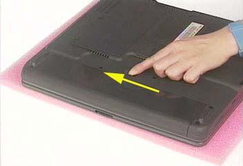
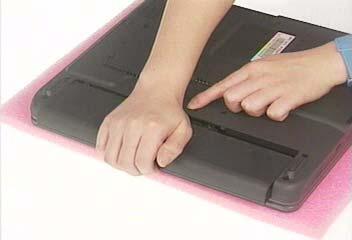
1. To remove the battery, push the battery release latch. 2. Then slide the battery out from the machine.
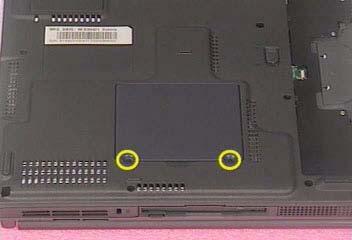
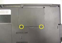
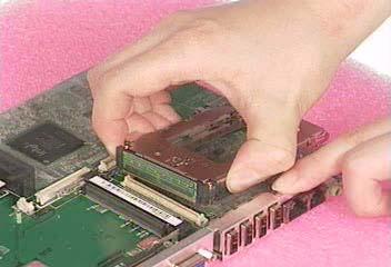
1. See “Removing the Battery” on page 50. 2. To remove the memory module from the machine, first remove the two screws holding the dimm cover.
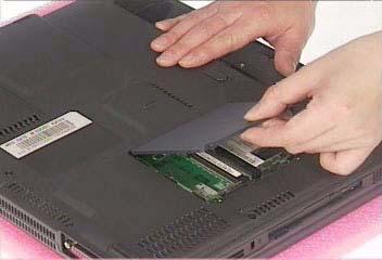
3. Remove the dimm cover.
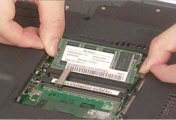
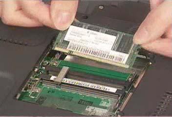
4. Pop up the memory. 5. Then remove the memory.
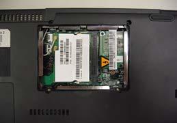
1. See “Removing the Battery” on page 50. 2. To remove the wireless LAN board, first remove the two screws holding the modem cover.
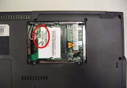
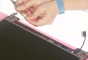
3. Remove the modem cover from the machine. 4. Disconnect the wireless antennae.
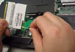
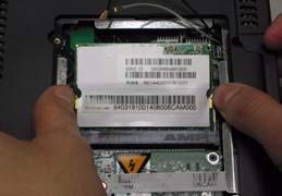
5. Pop out the wireless LAN board. 6. To remove the modem board, first remove the two screws fastening the modem board.
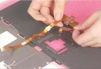
7. Detach the modem board and disconnect the modem cable carefully, then remove the modem board.


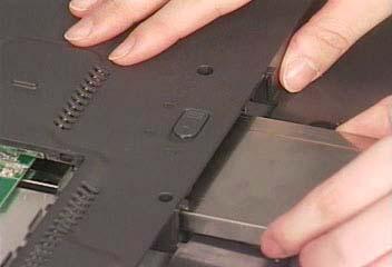
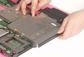
1. See “Removing the Battery” on page 50. 2. To remove the hard disk drive, pull the hard disk dirve carefully.
3. Then take the hard disk drive out of the main unit.
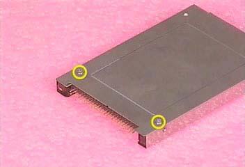
Disassembling the Hard Disk Drive Module
1. See “Removing the Battery” on page 50. 2. See “Removing the LCD Module” on page 54. 3. Remove the two screws that fasten the HDD holder.
4. Detach the hard disk drive from the HDD holder.

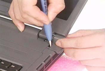
Removing the Middle Cover
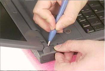
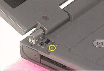
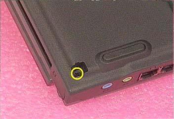
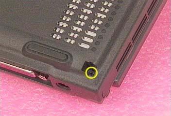
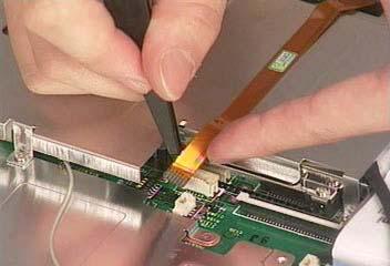
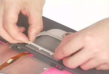
1. See “Removing the Battery” on page 50. 2. To remove the middle cover, first use a plastic flat screwdriver to remove the right hinge cap. 3. Remove the screw that secures the middle cover.
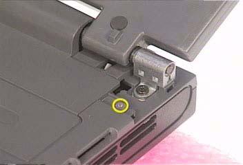
4. Remove the left hinge cap. 5. Then remove the screw holding the middle cover on the other side.
6. Detach the middle cover from the machine.
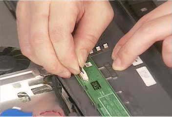
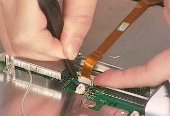
7. Disconnect the launch board cable then remove the middle cover off the main unit.
Removing the Launch Board
Removing the LCD Module
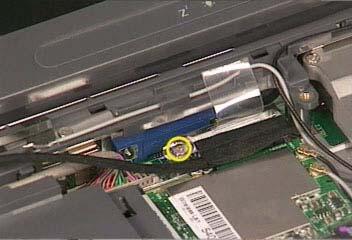
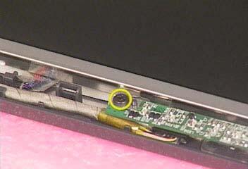
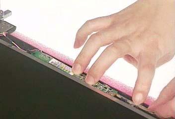
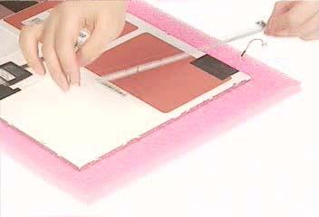
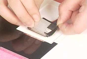
1. See “Removing the Battery” on page 50. 2. See “Removing the Middle Cover” on page 54. 3. See “Removing the Launch Board” on page 54. 4. Remove the screw that fastens the LCD coaxial cable and disconnect the cable. Then disconnect the
LCD inverter cable.
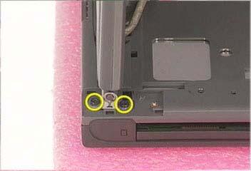
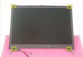
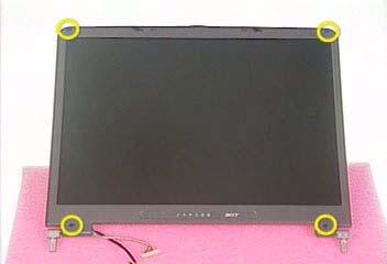
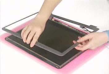
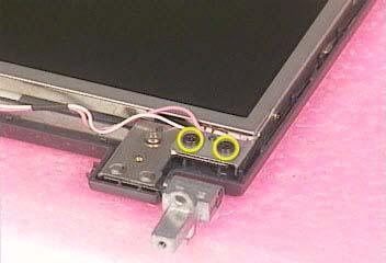
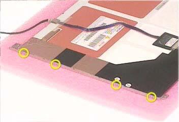
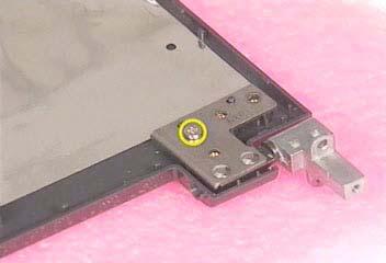
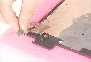
5. Remove the four screws holding the LCD hinge; two on the right and two on the left.Remove the four screws holding the LCD hinge; two on the right and two on the left.
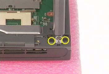
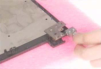
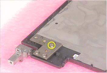
6. Remove the two screws on the bottom; one on the right and the other on the left.
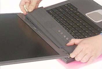
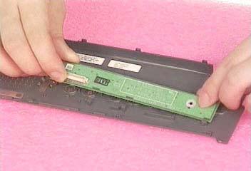
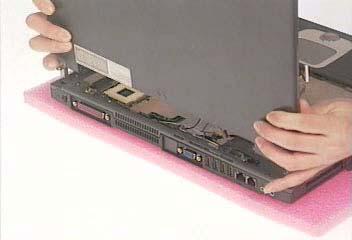
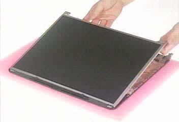
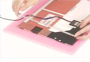
7. Then you can remove the entire LCD module from the main unit.
Removing the LCD Bezel
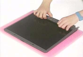
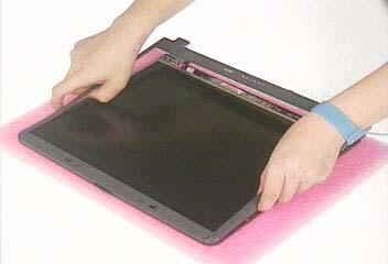
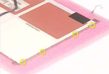
1. See “Removing the Battery” on page 50. 2. See “Removing the Middle Cover” on page 54. 3. See “Removing the Launch Board” on page 54. 4. See “Removing the LCD Module” on page 55. 5. Use plastic tweezers to remove the four screw pads, and then remove the four screws that fasten the LCD bezel.
6. Snap off the bezel carefully, and then remove the LCD bezel from the LCD module.
Removing the Inverter Board (15” LCD)
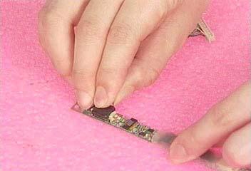
1. See “Removing the Battery” on page 50. 2. See “Removing the Middle Cover” on page 54. 3. See “Removing the Launch Board” on page 54. 4. See “Removing the LCD Module” on page 55. 5. See “Removing the LCD Bezel” on page 57. 6. To remove the inverter board, first remove one screw from the inverter board.
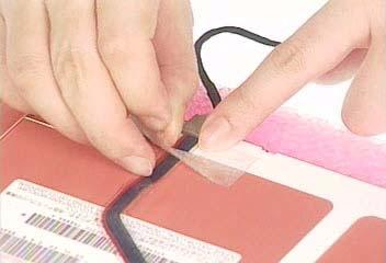
7. Disconnect the LCD power cable then disconnect the inverter cable from the inverter board.
NOTE: Please arrange the LCD inverter cable well to the LCD panel as the picture below shows when you reassemble the LCD module.
Removing the 15” TFT LCD
1. See “Removing the Battery” on page 50. 2. See “Removing the Middle Cover” on page 54. 3. See “Removing the Launch Board” on page 54. 4. See “Removing the LCD Module” on page 55. 5. See “Removing the LCD Bezel” on page 57. 6. See “Removing the Inverter Board (15” LCD)” on page 57. 7. To remove the LCD, first remove the four screws that secure the LCD hinges.
8. Then take the LCD out of the LCD panel.

Removing the LCD Brackets
2. See “Removing the Middle Cover” on page 54. 3. See “Removing the Launch Board” on page 54. 4. See “Removing the LCD Module” on page 55. 5. See “Removing the LCD Bezel” on page 57. 6. See “Removing the Inverter Board (15” LCD)” on page 57. 7. See “Removing the 15” TFT LCD” on page 58. 8. Remove the four screws holding the right LCD bracket.Then remove the right bracket.
9. Remove the four screws holding the left LCD bracket. Then remove the left bracket..
Removing the LCD Coaxial Cable
1. See “Removing the Battery” on page 50. 2. See “Removing the Middle Cover” on page 54. 3. See “Removing the Launch Board” on page 54. 4. See “Removing the LCD Module” on page 55. 5. See “Removing the LCD Bezel” on page 57. 6. See “Removing the Inverter Board (15” LCD)” on page 57. 7. See “Removing the 15” TFT LCD” on page 58. 8. Tear off the mylar fastening the LCD coaxial cable, then disconnect the coaxial cable.
Removing the LCD Hinges
1. See “Removing the Battery” on page 50.
2. See “Removing the Middle Cover” on page 54. 3. See “Removing the Launch Board” on page 54. 4. See “Removing the LCD Module” on page 55. 5. See “Removing the LCD Bezel” on page 57. 6. See “Removing the Inverter Board (15” LCD)” on page 57. 7. See “Removing the 15” TFT LCD” on page 58. 8. Remove the screw holding the right hinge, then remove the right hinge.
Removing the Keyboard
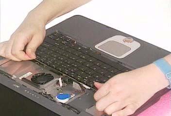
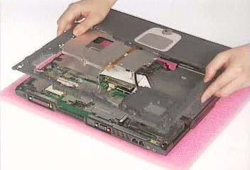
1. See “Removing the Battery” on page 50. 2. See “Removing the Middle Cover” on page 54. 3. To remove the keyboard, carefully pull the keyboard out and upwards as the pticute shows.
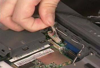
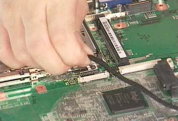
4. Use a plastic tweezers or a plastic flat screwdriver to disconnect the keyboard cable from the main board carefully, then remove the keyboard.
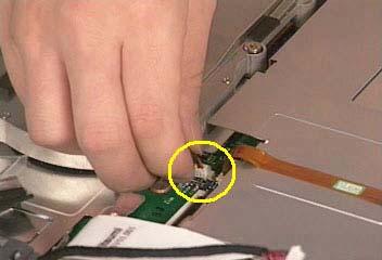
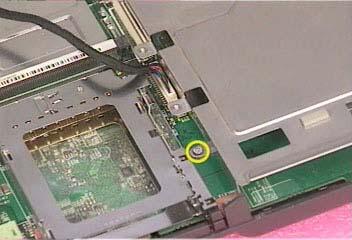
Removing the RTC Battery
1. See “Removing the Battery” on page 50. 2. See “Removing the Middle Cover” on page 54. 3. See “Removing the Keyboard” on page 61. 4. Disconnect the RTC battery cable then remove it.

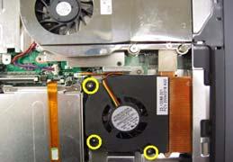
Removing the Fan
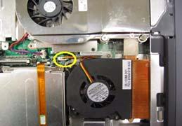
1. See “Removing the Battery” on page 50. 2. See “Removing the Middle Cover” on page 54. 3. See “Removing the Keyboard” on page 61. 4. Disconnect the fan cable and remove the three screws fastening the fan. Then remove the fan.
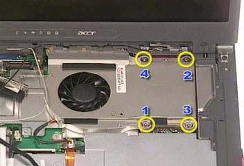
Removing the Thermal Module
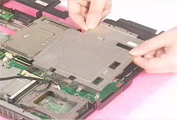
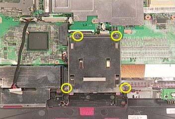
1. See “Removing the Battery” on page 50. 2. See “Removing the Middle Cover” on page 54. 3. See “Removing the Keyboard” on page 61. 4. See “Removing the Fan” on page 61. 5. Disconnect the fan cable then remove the four screws fastening the thermal module.
6. Then remove the thermal module.

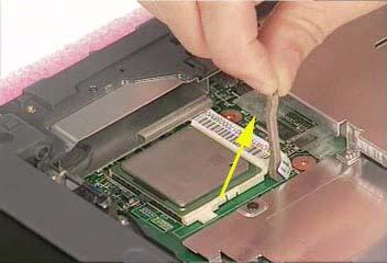
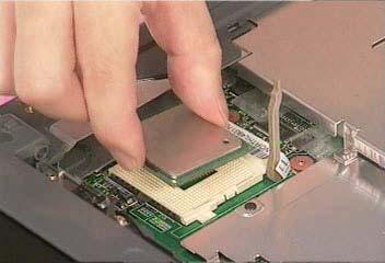
Removing the Processor
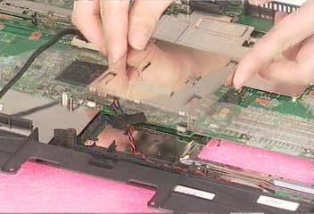
1. See “Removing the Battery” on page 50. 2. See “Removing the Middle Cover” on page 54. 3. See “Removing the Keyboard” on page 61. 4. See “Removing the RTC Battery” on page 61. 5. See “Removing the Fan” on page 61. 6. See “Removing the Thermal Module” on page 62. 7. Lift up the CPU socket lever. Then remove the CPU. Remember to press down the lever as the video shows after you remove the CPU.
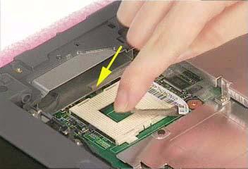
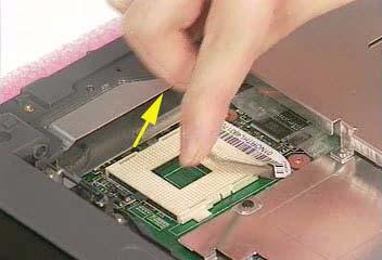
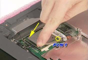
Installing the Processor
1. See “Removing the Battery” on page 50. 2. See “Removing the Middle Cover” on page 54. 3. See “Removing the Keyboard” on page 61. 4. See “Removing the RTC Battery” on page 61. 5. See “Removing the Fan” on page 61. 6. See “Removing the Thermal Module” on page 62. 7. Lift up the CPU lever, then place the CPU back to the CPU socket. Please remember to press the CPU lever after you put the CPU back to the socket.

Removing the Upper Case Assemly
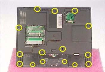
3. Remove the 6 screws that secure the upper case to the lower case. Then turn over the main unit and remove the 15 screws holding the lower case to the upper case.
4. Then take the upper case assembly off the main unit.
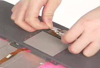
Removing the Touchpad Board
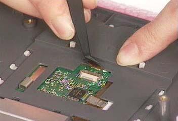
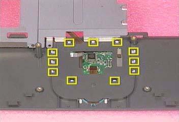
1. See “Removing the Battery” on page 50. 2. See “Removing the Middle Cover” on page 54. 3. See “Removing the Keyboard” on page 61. 4. See “Removing the Upper Case Assemly” on page 63. 5. To detach the touch pad board, first disconnect the touch pad cable from the touch pad board with a plastic tweezers.Then release the touchpad cover lock on the back as the picture shows.
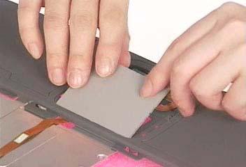
6. Remove the touchpad cover, the remove the touchpad button pad. Finally remove the touchpad board from the upper case.
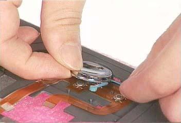
Removing the Touchpad Cable
3. See “Removing the LCD Module” on page 55. 4. See “Removing the Keyboard” on page 61. 5. See “Removing the Upper Case Assemly” on page 63. 6. See “Removing the Touchpad Board” on page 64. 7. Remove the touchpad scroll key then remove the touchpad cable.
Removing the Floppy Disk Drive Module
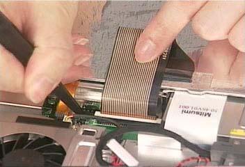
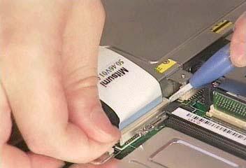
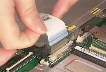
NOTE: This portion is prepared for the models with floppy disk drive. If you get the machine without floppy disk drive module, please skip this part. 1. See “Removing the Middle Cover” on page 54. 2. See “Removing the LCD Module” on page 55. 3. See “Removing the Keyboard” on page 61. 4. See “Removing the Upper Case Assemly” on page 63. 5. Disconnect the FDD cable from the main board.
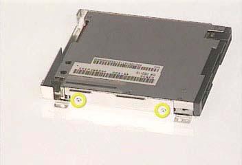
6. Remove the two screws hastening the FDD module. Detach the FDD module from the lower case.

Dissembling the Floppy Disk Drive Module
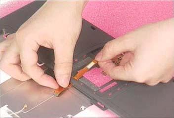
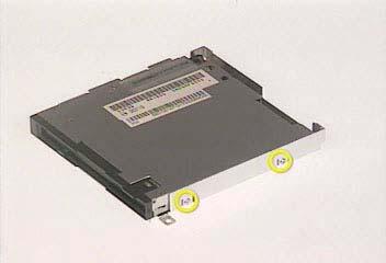
1. Disconnect the FDD cable. 2. Remove the two screws that fasten the FDD bracket on one side.
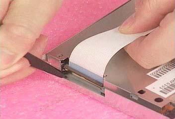
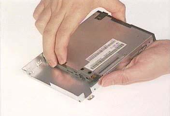
3. Remove another two screws holding the FDD bracket on the other side. Then take the FDD off the FDD bracket.
Removing the VGA Thermal Plate
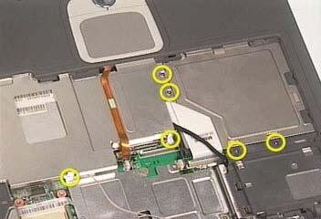
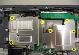
1. See “Removing the Battery” on page 50. 2. See “Removing the Middle Cover” on page 54. 3. See “Removing the Keyboard” on page 61. 4. See “Removing the Fan” on page 61. 5. See “Removing the Thermal Module” on page 62. 6. Remove the seven screws holding the VGA thermal plate then remove it.
Removing the CPU Heatsink Plate
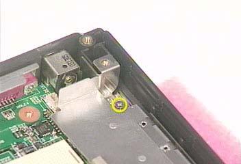
1. See “Removing the Battery” on page 50. 2. See “Removing the Middle Cover” on page 54. 3. See “Removing the Keyboard” on page 61. 4. See “Removing the Floppy Disk Drive Module” on page 65. 5. Remove the screw that fastens the CPU heatsink plate then remove it.
Removing the Second Fan Bracket
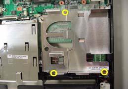
1. See “Removing the Battery” on page 50. 2. See “Removing the Middle Cover” on page 54. 3. See “Removing the LCD Module” on page 55. 4. See “Removing the RTC Battery” on page 61. 5. See “Removing the Fan” on page 61. 6. See “Removing the Thermal Module” on page 62. 7. Remove the three screws that fasten the second fan bracket then remove the bracket.
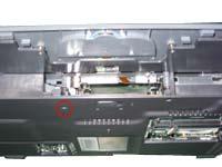
Removing the ODD Module(1)
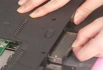
1. See “Removing the Battery” on page 50. 2. Remove the screw that fastens the ODD bracket on the bottom. Push the ODD module at the point the red arrow indicates hard.Then remove the ODD module from the lower case.
NOTE: If you need to replace the ODD module only, you can remove the ODD module as the steps above.
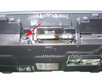
Removing the ODD Module(2)
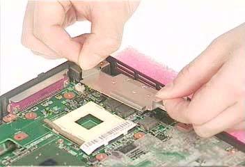
5. Push the ODD module outwards then take the ODD out of the support bracket. Remove the screw that fastens the ODD support bracket then remove it.
Removing the HDD Bracket
1. See “Removing the Battery” on page 50. 2. See “Removing the Middle Cover” on page 54. 3. See “Removing the Keyboard” on page 61. 4. See “Removing the Upper Case Assemly” on page 63. 5. Remove the four screws holding the HDD bracket, then remove the HDD bracket.
Removing the Main Board
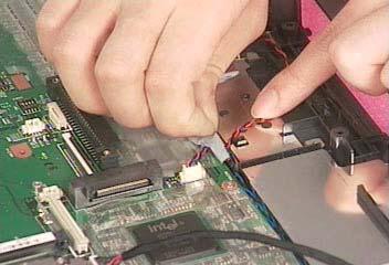
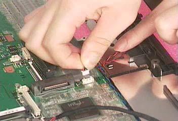
1. See “Removing the Battery” on page 50. 2. See “Removing the Middle Cover” on page 54. 3. See “Removing the Keyboard” on page 61. 4. See “Removing the Fan” on page 61. 5. See “Removing the Thermal Module” on page 62. 6. See “Removing the Upper Case Assemly” on page 63. 7. See “Removing the VGA Thermal Plate” on page 66. 8. See “Removing the CPU Heatsink Plate” on page 66. 9. See “Removing the Floppy Disk Drive Module” on page 65. 10. See “Removing the Second Fan Bracket” on page 67. 11. See “Removing the ODD Module(2)” on page 67. 12. See “Removing the HDD Bracket” on page 68. 13. Disconnect the launch board cable. Tear off the tape that fastens the speaker set cable. Then disconnect the speaker set cable.
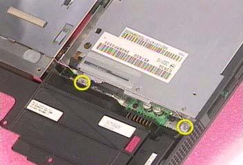
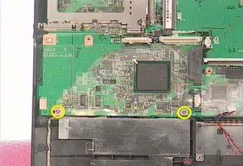
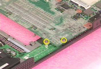
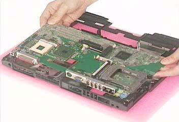
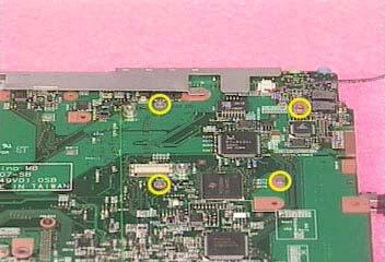
14. Remove the two screws holding the main board as the picture shows. Remove another two screws that fasten the main board. Then detach the main board from the lower case carefully.
Removing the DC Board
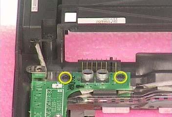
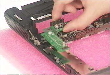
1. See “Removing the Battery” on page 50. 2. See “Removing the Middle Cover” on page 54. 3. See “Removing the Keyboard” on page 61. 4. See “Removing the Fan” on page 61. 5. See “Removing the Thermal Module” on page 62. 6. See “Removing the Upper Case Assemly” on page 63. 7. See “Removing the VGA Thermal Plate” on page 66. 8. See “Removing the CPU Heatsink Plate” on page 66. 9. See “Removing the Floppy Disk Drive Module” on page 65. 10. See “Removing the Second Fan Bracket” on page 67. 11. See “Removing the ODD Module(2)” on page 67. 12. See “Removing the HDD Bracket” on page 68. 13. See “Removing the Main Board” on page 68. 14. Remove the two screws that fasten the DC board. Then detach the DC board from the lower case.
Removing the I/O Port Bracket
1. See “Removing the Battery” on page 50.
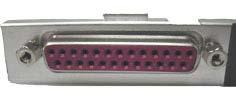
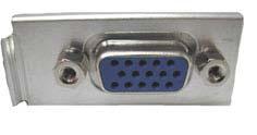
2. See “Removing the Middle Cover” on page 54. 3. See “Removing the Keyboard” on page 61. 4. See “Removing the Fan” on page 61. 5. See “Removing the Thermal Module” on page 62. 6. See “Removing the Upper Case Assemly” on page 63. 7. See “Removing the VGA Thermal Plate” on page 66. 8. See “Removing the CPU Heatsink Plate” on page 66. 9. See “Removing the Floppy Disk Drive Module” on page 65. 10. See “Removing the Second Fan Bracket” on page 67. 11. See “Removing the ODD Module(2)” on page 67. 12. See “Removing the HDD Bracket” on page 68. 13. See “Removing the Main Board” on page 68. 14. Remove the four hex screws to detach the I/O port bracket from the main board.
Removing the PCMCIA Slot
1. See “Removing the Battery” on page 50. 2. See “Removing the Middle Cover” on page 54. 3. See “Removing the Keyboard” on page 61. 4. See “Removing the Fan” on page 61. 5. See “Removing the Thermal Module” on page 62. 6. See “Removing the Upper Case Assemly” on page 63. 7. See “Removing the VGA Thermal Plate” on page 66. 8. See “Removing the CPU Heatsink Plate” on page 66. 9. See “Removing the Floppy Disk Drive Module” on page 65. 10. See “Removing the Second Fan Bracket” on page 67. 11. See “Removing the ODD Module(2)” on page 67. 12. See “Removing the HDD Bracket” on page 68. 13. See “Removing the Main Board” on page 68. 14. Remove the four screws that secure the PCMCIA slot, then remove the PCMCIA slot from the lower case.
Removing the Speaker Set
1. See “Removing the Battery” on page 50. 2. See “Removing the Middle Cover” on page 54. 3. See “Removing the Keyboard” on page 61. 4. See “Removing the Floppy Disk Drive Module” on page 65. 5. See “Removing the VGA Thermal Plate” on page 66. 6. See “Removing the CPU Heatsink Plate” on page 66. 7. See “Removing the Second Fan Bracket” on page 67. 8. See “Removing the HDD Bracket” on page 68. 9. See “Removing the Main Board” on page 68. 10. See “Removing the DC Board” on page 69. 11. Tear off the tape fastening the speaker set cable. Then remove the four screws that secure the speaker set. Remove the speaker set from the lower case.
Base Unit to Wireless Unit
1. Turn out the two screws fastening the modem cover then open the cover. 2. Connect the wirless antennae. 3. Insert the wireless LAN board to the wireless socket on the main board. 4. Close the modem cover and fasten the cover with the two screws.
NOTE: You must connect the wireless antennae before you insert the wireless LAN board to the socket. If you insert the wireless LAN card first, the pressure you press to fasten the wireless antennae may damage the main board.