5 minute read
Montana axle control system pump


Key to diagram:
K-1 Release parking brake ram K-2 Service brake ram N Parking brake emergency operation (mechanical) S Brake air gap adjusting screw
110 Oil tank 112 Return filter
205 Working hydraulics pump 211 Ground drive variable-displacement pump 217 Radiator chaff screen pump 231 Montana axle control system pump 313 Ground drive pump servo control hydraulic cylinder 3003-1Service brake / Parking brake right hydraulic cylinder 3003-2Service brake / Parking brake left hydraulic cylinder
516 Service brake accumulator 0.75 l / 80 bar
614 Front attachment lower flow control valve 642-1 Service brake valve, right 642-2 Service brake valve, left
703 Working hydraulics pressure relief valve 706-5 Rotary chaff screen pressure relief valve 150 bar 732 Non-return valve 743 Lower front attachment pilot spool
901 Working hydraulics measuring point
B90 Brake circuit charge pressure sensor
Y77 Working hydraulics master valve solenoid valve Y85 Raise front attachment solenoid valve Y87 Lower front attachment solenoid valve
Z79-3 Left brake circuit pressure actual value switch (accumulator warning) Z80-3 Right brake circuit pressure actual value switch (accumulator warning)
Description of function:
Emergency operation The parking brake system consists of a spring-type accumulator in the brake cylinders. The low-pressure circuit of the machine is used for releasing the parking brake.
If the hydraulic circuit fails (depending on the diesel engine!), the parking brake can be released manually, using screw N. To do this, screw in screw N ñ see Repair Manual.
Brake air gap The Montana brake system is a wet multi-disc brake. To ensure freewheeling of the discs when the brake is not actuated, an air gap can be adjusted at screw S ñ see Repair Manual.
4
Low-pressure Hydraulic System
4.1 Low-pressure hydraulic system ñ Basic functions...............................................................4-3
4.2 Low-pressure hydraulic system ñ Additional Montana functions.....................................4-45
4.1
Low-pressure hydraulic system ñ Basic functions
4.1.1 Low-pressure hydraulic system circuit diagram LEXION 600 (Wheeled machine)..........4-6
4.1.2 Low-pressure hydraulic system circuit diagram LEXION 600 Terra Trac.......................4-10
4.1.3 Low-pressure Hydraulic System Diagram LEXION 580 - 510............................................4-14
4.1.4 Pressure Relief Valve Of Low-pressure Hydraulic System................................................4-16
4.1.5 Low-pressure hydraulic system solenoid valves................................................................4-18
3/2-way valve (threshing mechanism circuit, grain tank unloading, chopper circuit, front attachment circuit)..................................................................................4-18 3/2 way valve (parking brake ñ Lexion 600).............................................................................4-22
4.1.6 Hydraulic Cylinder of Low-pressure Hydraulic System.....................................................4-24
Threshing mechanism clutch engage (step cylinder)...............................................................4-24 Front attachment clutch with rotary coupling............................................................................4-26 Straw chopper clutch................................................................................................................4-28 Grain tank unloading................................................................................................................4-30 Sample gate (moisture measurement).....................................................................................4-32 Grain elevator chain tension.....................................................................................................4-34 Parking brake (Lexion 600 wheeled machine).........................................................................4-36 Parking brake (Lexion 600 TerraTrac ñ half-tracks).................................................................4-38
4.1.7 3-D Cleaning System..............................................................................................................4-40
Pendulum housing with valve and hydraulic cylinder...............................................................4-40
4.1.8 Grain Tank Unloading Chain Lubrication............................................................................4-42
Lubricant pump with reservoir.................................................................................................. 4-42
4.1.1
Low-pressure hydraulic system circuit diagram
LEXION 600
Wheeled machine
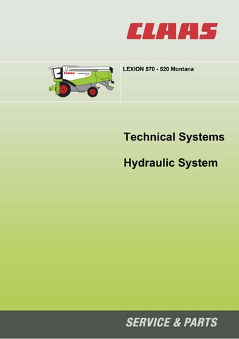
4.1.1 Low-pressure hydraulic system circuit diagram LEXION 600 (Wheeled machine)
Key to diagram:
102 Pressure filter 115 Grain tank unloading lubricant reservoir
209 Ground drive feed pump..............................20 / 26 cm3/ rev. 211 Ground drive variable-displacement pump..100 / 130 cm3/rev. 213 Reel drive pump...........................................15 cm3/rev. 218 Steering hydraulics pump 232 Grain tank unloading lubricant pump 2069 Additional charge pump
301 3-D sieve pan hydraulic cylinder 312 Threshing mechanism coupling hydraulic cylinder 313 Ground drive pump servo control hydraulic cylinder 321 Grain tank unloading hydraulic cylinder 335 Sample gate hydraulic cylinder (moisture measurement) 339 Servo gearshift hydraulic cylinder 347 Straw chopper clutch hydraulic cylinder 352 Front attachment clutch hydraulic cylinder 358 Grain elevator chain tension hydraulic cylinder 3003 Service brake / Parking brake hydraulic cylinder
407 Orifice plate G..............................................ÿ 1 mm 412 Orifice plate M..............................................ÿ 2 mm 426 Hollow screw with restrictor bore.................ÿ 0.8 mm 441 Rotary coupling
515 Accumulator
601 3-D sieve pan pendulum control valve 606 Ground drive servo control hydraulic valve
706-5 Pressure relief valve.....................................100±5 bar 710 Ground drive filter bypass valve 715 Servo gearshift short-circuit valve 729 Pressure relief valve.....................................19+4 bar 731 Non-return valve 732 Non-return valve 748 One-way restrictor valve..............................ÿ 0.8 mm 760 One-way restrictor, one-sided
910 Measuring port
Key to diagram:
Y21 Threshing mechanism clutch engage solenoid valve Y35 Grain tank unloading solenoid valve Y52 Sample gate solenoid valve (moisture measurement) Y76 Straw chopper clutch solenoid valve Y88 Front attachment clutch solenoid valve (proportional) Y105 Differential lock Y106 Parking brake Y107 Transmission ñ1st gear Y108 Transmission ñ 2nd gear Y141 Ground drive forward Y142 Ground drive backward Y143 Ground drive/Shut-off valve Z46 Oil pressure switch.......................................12 bar
k when ÑActive-Tracì rear drive axle is fitted
A Consumer port T Tank port P Ground drive feed pump port P2 Working hydraulics port P4 Rotary chaff screen port P5 Low-pressure port S Grain tank unloading lubricant brush port
M2 High pressure backward measuring port M4 Actuating pressure backward measuring port M5 Actuating pressure forward measuring port
VI Low-pressure hydraulics valve block
Malfunctions:
When there are malfunctions in the low-pressure hydraulic system, only consumers which have been shut-down can cause a pressure drop in the system. In this way, the reason of a malfunction can be quickly determined by shutting down individual functions while keeping a pressure gauge connected (measuring port 910).
Note: Oil supply of the low-pressure hydraulic system is ensured by the ground drive feed pump (209). The orifice plate (412) limits the volume flow to the lowpressure hydraulic system to 5-7 l/min at the rated pressure (19+4 bar). This ensures that the feed pressure for the hydrostatic ground drive will not collapse even in case of large leaks in the low-pressure hydraulic system.
4.1.2
Low-pressure hydraulic system circuit diagram
LEXION 600 Terra Trac
Half-tracks
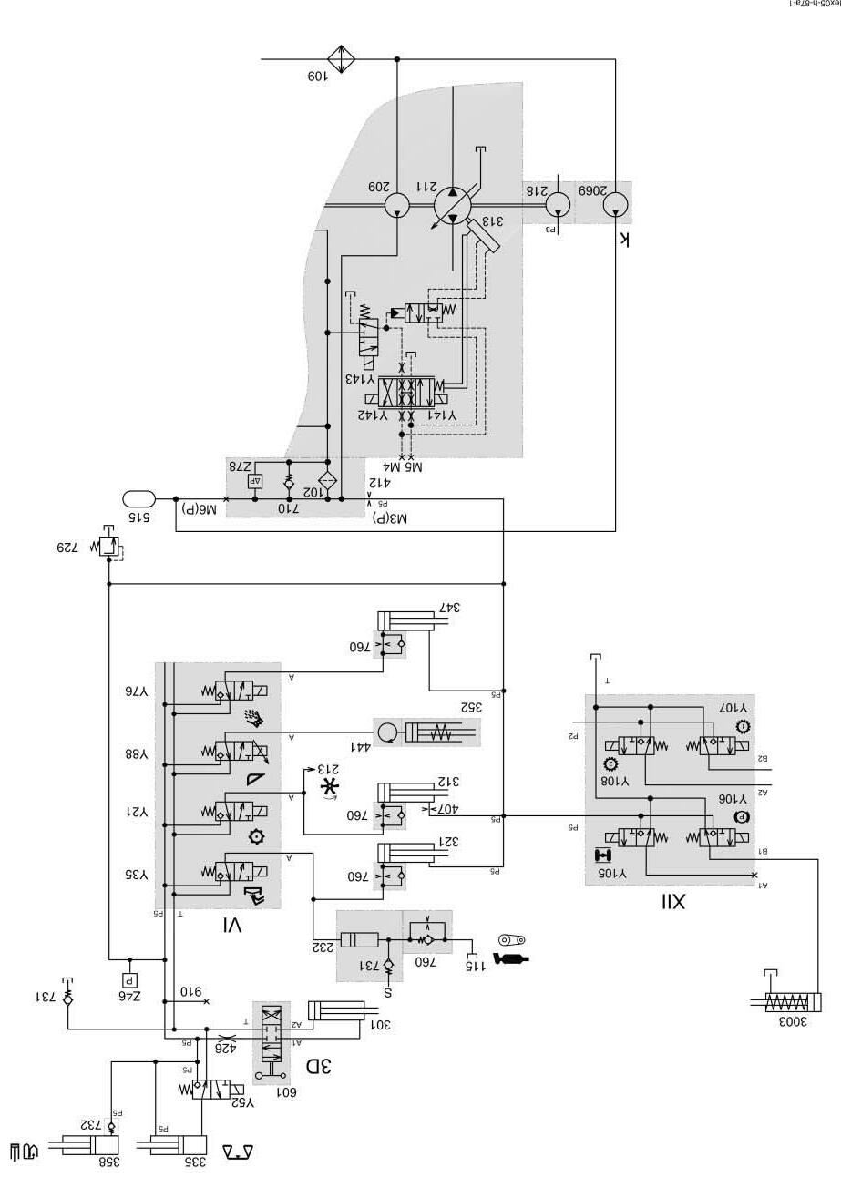
4.1.2 Low-pressure hydraulic system circuit diagram LEXION 600 Terra Trac
Key to diagram:
102 Pressure filter 115 Grain tank unloading lubricant reservoir
209 Ground drive feed pump..............................20 / 26 cm3/ rev. 211 Ground drive variable-displacement pump..100 / 130 cm3/rev. 213 Reel drive pump...........................................15 cm3/rev. 218 Steering hydraulics pump 232 Grain tank unloading lubricant pump 2069 Additional charge pump
301 3-D sieve pan hydraulic cylinder 312 Threshing mechanism coupling hydraulic cylinder 313 Ground drive pump servo control hydraulic cylinder 321 Grain tank unloading hydraulic cylinder 335 Sample gate hydraulic cylinder (moisture measurement) 339 Servo gearshift hydraulic cylinder 347 Straw chopper clutch hydraulic cylinder 352 Front attachment clutch hydraulic cylinder 358 Grain elevator chain tension hydraulic cylinder 3003-1 Service brake / Parking brake right hydraulic cylinder 3003-2 Service brake / Parking brake left hydraulic cylinder
407 Orifice plate G..............................................ÿ 1 mm 412 Orifice plate M..............................................ÿ 2 mm 426 Hollow screw with restrictor bore.................ÿ 0.8 mm 441 Rotary coupling
515 Accumulator
601 3-D sieve pan pendulum control valve 606 Ground drive servo control hydraulic valve
706-5 Pressure relief valve.....................................100±5 bar 710 Ground drive filter bypass valve 715 Servo gearshift short-circuit valve 729 Pressure relief valve.....................................19+4 bar 731 Non-return valve 732 Non-return valve 748 One-way restrictor valve..............................ÿ 0.8 mm 760 One-way restrictor, one-sided
910 Measuring port