1 minute read
REMOVING THE BEVEL GEAR AND DIFFERENTIAL...............................................................................................D1


Bevel gear and differential
Removing the bevel gear and differential
– Immobilise the tractor (see "Preliminary operations prior to working on the front axle"). – Remove the front axle.
Note: To remove the drive pinion and differential lock assembly, the universal shafts must be removed beforehand.
– Drain the differential by unscrewing the plug (19),(Fig. 25). – Remove the bearing (12) by unscrewing the screw (13). – Extract the bushes (9), (10), (7). – Remove the ring seal (1). – Loosen the bevel pinion nut (2) using tool n° 6005006536. – Support then remove the cover (16) containing the drive pinion and differential. – Remove the screws (34) as well as the pawls (35). – Mark the differential bearing flanges (22) in relation to the cover (16) to avoid reversing them on refitting. – Unscrew the toothed nuts (36) using tool n°6005006534. – Remove the screws (23).
Note: Do not reverse the bearings of the differential bearing blocks if they are not replaced.
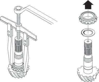
– Put the cover fitted with the bevel pinion in a vice. – Hold the drive pinion. – Unscrew the nut (2) from the bevel pinion and extract it. – Extract the inner bush from the bearing with an extractor. – Extract the outer rings from the bevel pinion bearings (4) and (18).
5
451hsm36
C
18
17
4
2
1
Fig. 27
451hsm34 Fig. 28