45 minute read
Steering/Body/Controls


The following steering components should be inspected periodically to ensure safe and proper operation:
A.Steering wheel secure.
B.Steering has equal and complete full-left and full-right turning capability.
C.Steering sector mounting bolts tight.
D.Ball joints not worn, cracked, or damaged.
E.Tie rods not bent or cracked.
F.Knuckles not worn, cracked, or damaged.
G.Cotter pins not damaged or missing.
H.Steering wheel tilt locks securely. The frame and welds should be checked periodically for damage, bends, cracks, deterioration, broken components, and missing components.
Steering Wheel
REMOVING 1.Remove the steering wheel cover; then match mark the steering shaft and steering wheel. NOTE: Any time steering components are disassembled, all connecting components should be marked for proper alignment during assembling. 2.Remove the lock clip from the steering shaft; then remove the nut securing the steering wheel and remove the steering wheel. INSPECTING 1.Inspect the steering wheel for cracks, missing padding, or broken spokes. 2.Inspect the splines for wear. 3.Check that the steering wheel is not bent. INSTALLING 1.Install the steering wheel aligning the two match marks; then apply a drop of red Loctite #271 to the threads of the nut and secure the steering wheel.
Tighten to 25 ft-lb (34 N-m). NOTE: If a new steering wheel is being installed, mark the wheel as close as possible to the old wheel mark; then check for proper positioning with the front wheels straight forward. 2.Install the lock clip on the steering shaft; then install the steering wheel cover. NOTE: If the hole in the steering shaft does not align with the slots in the castle nut, tighten the nut slightly until the next slot aligns with the hole.
MOD220
Steering System
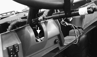
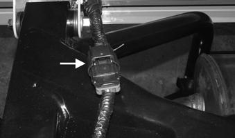
REMOVING EPS ASSEMBLY NOTE: Thoroughly troubleshoot the electronic power steering (EPS) system (if equipped) prior to replacing the EPS assembly (see Electrical System — Electronic Power Steering (EPS)) as there are several possible external causes for system failure. NOTE: The EPS assembly is only serviceable as an assembly. 1.Disconnect the battery; then remove the hood, upper hood, dash upper and dash lower; then disconnect the EPS electrical connection.

MOD269
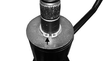
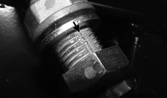
2.Align the steering rack with the marks with the wheels straight ahead.

MOD173
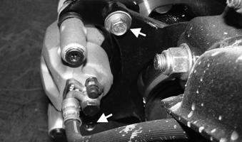
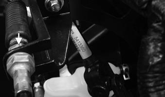
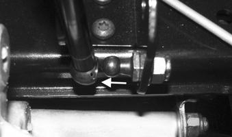
3.Remove the input shaft cap screw and lock nut of the
EPS; then remove the output shaft cap screw and lock nut of the EPS. Discard lock nuts. Inspect cap screws and replace if damaged.
MOD270A

MOD271
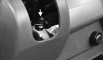
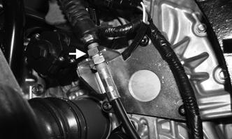
4.Remove the two cap screws securing the steering tilt assembly; then pull the U-joint off of the input shaft of the EPS; then secure the steering tilt assembly out of the way.


MOD272
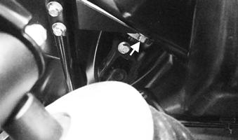
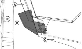
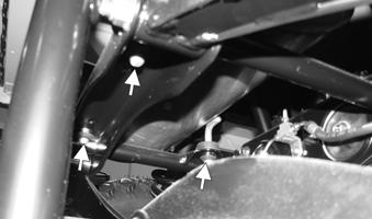
5.Remove the two cap screws on the occupant side and the one cap screw in the front left inner fender securing the EPS; then gently remove the EPS taking note that the output shaft should slide away from the
U-joint.

MOD274
MOD273
INSTALLING STEERING SHAFT/EPS ASSEMBLY NOTE: Both the input and output shafts of the EPS have a notch that will only align one way with the U-joints.
MOD275
MOD276
1.Align the steering rack with the marks; then reinstall the output shaft of the EPS into the U-joint going to the steering rack; then install the EPS into position.
MOD173
2.Reinstall the two cap screws on the occupant side and the one cap screw in the front left inner fender securing the EPS. Finger tighten only. 4.Reinstall the input shaft cap screw and new lock nut to the EPS; then reinstall the output shaft cap screw and new lock nut of the EPS. Tighten both to 24 ft-lb (32.6 N-m).
MOD270A
MOD274 MOD271
5.Reconnect the EPS electrical connection with dielectric grease on the terminals; then tighten the cap screws from step 2 to 16 ft-lb (21.8 N-m); then reinstall the dash lower, dash upper, upper hood, and hood; then reconnect the battery.

MOD273
3.Align the U-joint of the steering tilt assembly to the input shaft of the EPS; then reinstall the two cap screws and new lock nuts securing the steering tilt assembly. Tighten to 16 ft-lb (21.8 N-m).
MOD269A
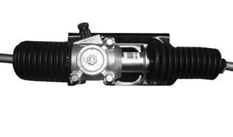
REMOVING RACK AND PINION NOTE: The steering rack should be aligned with the factory marks and marked on the U-joint prior to removal.
MOD272
MOD173
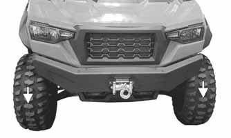
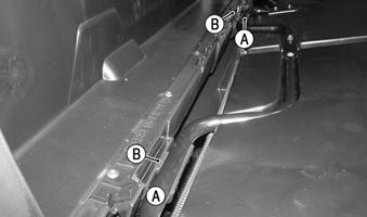
1.Using a suitable lift and stands lift the vehicle until the front wheels are off the ground; then remove the front wheels. 2.Remove the cotter pins (A) and castle nuts (B) securing the outer tie rod ends to the knuckles; then remove the outer tie rod ends from the knuckles.

MOD315
MOD316
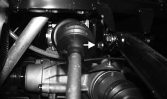
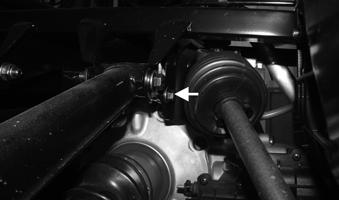
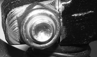
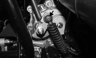
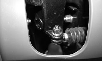
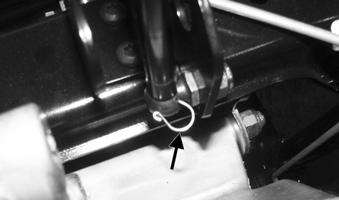
3.Remove the cap screw and lock nut securing the
U-joint to the rack and pinion. Discard lock nut.
Inspect cap screw and replace if damaged.

MOD317
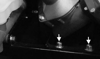
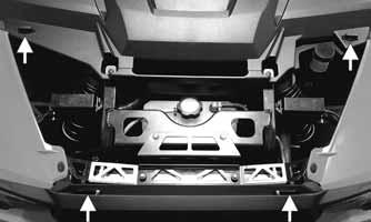
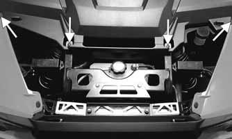
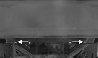
4.Remove the four cap screws and lock nuts securing the rack and pinion bracket to the frame. Discard lock nuts. Inspect cap screws and replace if damaged.

MOD319
MOD320
MOD321
5.Disconnect the U-joint from the rack and pinion; then remove the rack and pinion from the passenger side.
INSPECTING RACK AND PINION 1.Inspect the tie rod ends for damaged threads, torn boots, or excessive wear. 2.Inspect the tie rods for bends or deformation. 3.Inspect the rack and pinion-to-tie rod boots for tears or deterioration.
MOD322
4.Check boot clamps for security. 5.Check that the steering assembly operates smoothly with no binding from full-left to full-right position. 6.Inspect for grease seepage from the steering assembly. NOTE: The steering assembly (rack and pinion) is only serviceable as an assembly; however, the tie rods and boots are replaceable. INSTALLING RACK AND PINION 1.From the passenger side, install the rack and pinion; then line up marks on the U-joint with the rack and pinion; then connect the U-joint to the rack and pinion. Install the bolt and new lock nut securing the Ujoint to the rack and pinion. Tighten to 45 ft-lb (61.2
N-m). 2.Install the four cap screws and new lock nuts securing the rack and pinion bracket to the frame. Tighten the upper cap screws to 45 ft-lb (61.2 N-m) and the lower cap screws to 16 ft-lb (21.8 N-m).
MOD319 MOD320
MOD321
3.Place the outer tie rod ends into the knuckles and secure with the castle nuts (B) (coated with red Loctite #271). Tighten to 32 ft-lb (43.5 N-m); then install new cotter pins (A) and spread the cotter pins. NOTE: If the slots in the castle nut (B) are not aligned with the hole in the outer tie rod end, tighten until the cotter pin can be installed.
MOD316
4.Install the wheels and using a crisscross pattern, tighten the wheel nuts in 20 ft-lb (27.2 N-m) increments to a final torque of 100 ft-lb (136 N-m); then lower the vehicle and remove the suitable lift and stands. REMOVING OUTER TIE RODS NOTE: Removal of the rack and pinion is not required to replace outer tie rods. 1.Using a suitable lift and stands lift the vehicle until the front wheels are off the ground; then remove the front wheels. 2.Remove the cotter pins (A) and castle nuts (B) securing the tie rod ends to the knuckles; then remove the outer tie rod ends from the knuckles.
MOD315
MOD316
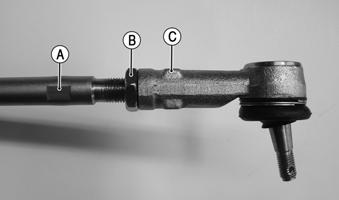
3.Measure the distance between shoulder of the tie rod shaft and the tie rod.

MOD323
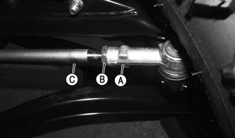
4.Using a wrench, loosen the lock nut (B) while holding the tie rod at the location indicated (C); then remove the tie rod with a wrench at the location indicated (C) while holding the tie rod shaft at the location indicated (A).
MOD323A
NOTE: Tie rods come as a complete assembly. No further disassembly is required. INSTALLING OUTER TIE RODS NOTE: If a new rack and pinion boot is to be installed. Install prior to putting on the outer tie rods. 1.Install the outer tie rod with a wrench at the location indicated (C) while holding the tie rod shaft at location indicated (A) until obtaining the measurement previously recorded when removing the outer tie rod.
MOD323A
2.Hold the outer tie rod with a wrench at the location indicated (C) and tighten the lock nut (B).
MOD323A
3.Place the outer tie rod ends into the knuckles and secure with the castle nuts (B) (coated with red Loctite #271). Tighten to 32 ft-lb (43.5 N-m); then install new cotter pins (A) and spread the cotter pins. NOTE: If the slots in the castle nut (B) are not aligned with the hole in the outer tie rod end, tighten until the cotter pin can be installed.
MOD316
MOD315
4.Install the wheels and using a crisscross pattern, tighten the wheel nuts in 20 ft-lb (27.2 N-m) increments to a final torque of 100 ft-lb (136 N-m); then lower the vehicle and remove the suitable lift and stands; then adjust the wheel alignment REMOVING INNER TIE RODS 1.Remove the rack and pinion from the vehicle (see
Removing Rack and Pinion section).
MOD322
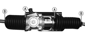
2.Remove the inner boot clamp (A) and outer boot clamp (B) of the side being removed; then slide the boot toward the outer tie rod of the side being removed.
MOD322A
3.Securely mount the rack and pinion to a vise or other holding fixture; then heat the inner tie rod; then with the inner tie rod still hot loosen and remove with an appropriate tool.

MOD324
INSTALLING INNER TIE RODS 1.With the threads coated with red Loctite #271, thread the inner tie rod end onto the rack and tighten securely. NOTE: Always attach the crowfoot to the torque wrench with the open end 90° to the torque wrench handle to ensure accurate torque application.
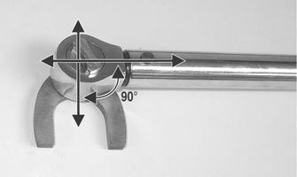
PR528A
2.Install the boot onto the rack and secure with the inner (A) and outer (B) boot clamps.
MOD322A
3.Reinstall the rack and pinion into the vehicle; then install the wheels and using a crisscross pattern, tighten the wheel nuts in 20 ft-lb (27.2 N-m) increments to a final torque of 100 ft-lb (136 N-m); then lower the vehicle and remove the suitable lift and stands; then adjust the wheel alignment. 4.Lower the vehicle and remove the suitable lift and stands; then adjust the wheel alignment.
Steering Knuckles
REMOVING AND DISASSEMBLING 1.Secure the vehicle on a support stand to elevate the wheel; then remove the wheel and retaining plate. ! WARNING
Make sure the vehicle is solidly supported on the support stand to avoid injury.
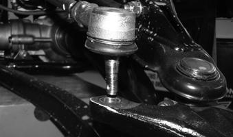
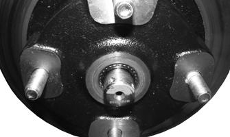
2.Remove the nut securing the hub. 3.Remove the brake caliper. 4.Remove the hub assembly. 5.Remove the cotter pin from the tie rod end and remove the tie rod end from the knuckle. 6.Remove the two cap screws securing the ball joints in the knuckle. Discard lock nuts. Inspect cap screws and replace if damaged. NOTE: Turn the cap screws and not the lock nuts. The lock nuts are held in place by the steering knuckle.
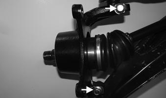
MOD325
7.With the cap screws completely removed tap the ball joint end out of the knuckle; then remove the knuckle. 8.Remove the snap ring securing the bearing in the knuckle; then press the bearing out of the knuckle.
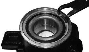
MOD327
CLEANING AND INSPECTING 1.Clean all knuckle components. 2.Inspect the bearing for pits, scoring, rusting, or premature wear. 3.Inspect the knuckle for cracks, breaks, or galling of the bearing surface. ASSEMBLING AND INSTALLING 1.Using a suitable press and driver, press the bearing into the knuckle until firmly seated; then install the snap ring with the sharp edge away from the bearing.
MOD327
2.Insert the CV shaft into the knuckle; then install the knuckle to the upper and lower ball joints and secure with the two cap screws and two new lock nuts.
Tighten to 45 ft-lb (61.2 N-m).
MOD325
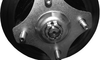
3.Install the tie rod end and secure with the nut (coated with red Loctite #271). Tighten to 32 ft-lb (43.5 N-m); then install a new cotter pin and spread the pin. 4.Apply a small amount of molybdenum grease to the hub splines.
MOD328
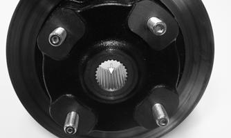
5.Install the hub assembly onto the splines of the shaft.
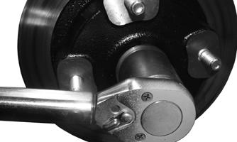
MOD329
6.Using Hub Retaining Wrench, secure the hub assembly with the nut. Tighten to 250 ft-lb (339 N-m).
MOD330
7.Install the retaining plate. NOTE: If necessary, tighten the hub nut clockwise to allow the retaining plate to sit flush with the hub.
MOD331

MOD332
8.Secure the brake caliper to the knuckle with the two new “patch-lock” cap screws. Tighten to 45 ft-lb (61.2 N-m).
9.Install the wheels and using a crisscross pattern, tighten the wheel nuts in 20 ft-lb (27.2 N-m) increments to a final torque of 100 ft-lb (136 N-m). 10.Remove the vehicle from the support stand.
Accelerator Pedal
REMOVING Disconnect the connector from the accelerator pedal; then remove the two lock nuts from the inner fender securing the accelerator pedal assembly to the splash panel and remove the accelerator pedal. Discard lock nuts.
MOD534


MOD535
INSTALLING Align the accelerator pedal studs with the holes in the splash panel and secure with two new lock nuts from the inner fender; then tighten to 8 ft-lb (10.9 N-m); then connect the connector to the accelerator pedal.
MOD534
Throttle Cable
This ROV/UTV is equipped with an Electronic Throttle Control (ETC) that does not have a traditional cable to control the throttle. The throttle is controlled by electrical wires (see the Electrical System section).
Shift Lever
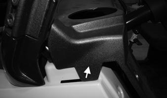
REMOVING 1.Remove the steering wheel. 2.Remove the lower and upper steering adjuster cap screws; then remove steering adjuster. With a suitable strap secure the steering wheel tilt assembly up and out of the way. 3.Remove the cap screw and lock nut securing the shift cable to the shift lever. Discard lock nut. Inspect cap screw and replace if damaged.
MOD305
4.Remove the two cap screws securing the adjuster bracket to the bottom of the steering housing.

MOD306
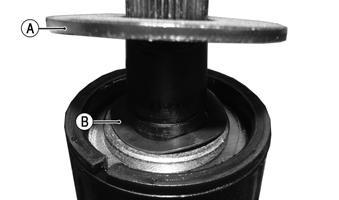
5.Remove the snap ring on the steering column; then remove the washer (A) and thrust washer (B); then slide the shift lever off of the steering housing.
MOD307
MOD308
INSTALLING 1.Lightly grease the inner portion of the shift lever; then slide the shift lever onto the steering housing; then install the thrust washer (B) and washer (A); then install the snap ring.
MOD308
MOD307
2.Install the adjuster bracket to the bottom of the steering housing; then install two the cap screws. Tighten to 24 in-lb (2.72 N-m).
MOD306
3.Position the shift cable to the shift lever using the existing cap screw and a new lock nut. Tighten to 6 ft-lb (8.2 N-m). 4.Position the steering adjuster into place; then install the lower and upper steering adjuster cap screws.
Tighten both to 6 ft-lb (8.2 N-m). Install the steering wheel. Tighten to 25 ft-lb (34 N-m). 5.Install the lock clip on the steering shaft; then install the steering wheel cover. NOTE: If the hole in the steering shaft does not align with the slots in the castle nut, tighten the nut slightly until the next slot aligns with the hole.
MOD220
Shift Cable
REMOVING NOTE: The shift cable can be accessed from the top by removing the floor or from the bottom by removing the skid plate. Removing from the bottom in most cases will be easier.
1.Remove the mid/upper dashboard; then remove the skid plate; then remove the lower steering adjuster cap screw. With a suitable strap secure the steering wheel tilt assembly up and out of the way. 2.Remove the cap screw and lock nut securing the shift cable to the shift lever. Discard lock nut. Inspect cap screw and replace if damaged.
MOD304
3.Loosen the lock nut securing the shift cable (underneath the dashboard). Slide the shift lever to the front of the vehicle and out. NOTE: The shift cable has two flat spots where the threads are that must be toward the metal housing for removal.
MOD309

MOD310
MOD303
4.Remove the E-clip securing the cable end to the shift arm stud.

MOD298
5.Loosen the adjuster nut; then remove the shift cable from the bracket. Remove any cable ties securing the shift cable to the chassis noting their location; then remove the shift cable.
MOD297A
INSTALLING 1.Route the cable into position making sure there are no kinks or sharp bends. 2.Guide the shift cable into the shift cable bracket.
Install the cable end to the shift arm stud and secure with a new E-clip. Secure the adjuster nut to the bracket.
MOD298

MOD297A
3.From under the dashboard, guide the shift cable into the bracket and install as shown; then secure the cable end to the shift lever using a new locknut.
Tighten to 6 ft-lb (8.2 N-m) Tighten the shift cable nut to 20 ft-lb (27.2 N-m).
XX382
MOD304
MOD303
4.Fasten the shift cable to the chassis with the previously noted cable tie locations. 5.Shift the transmission through all positions making sure the each gear position illuminates the appropriate gears selected and that the Park Indicator illuminates only when fully in Park. Verify transaxle is in park by attempting to gently push the vehicle; then verify vehicle moves in low range without grinding gears. Adjust as necessary. If no adjustment is necessary tighten the adjuster nuts for the shifter cable on the transaxle to 20 ft-lb (27.2 N-m) 6.Install the mid/upper dashboard upper; then the skid plate; then the lower steering adjuster cap screw.
LCD Gauge
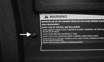
REMOVING/INSTALLING To remove the gauge, pull out on one side of it; then disconnect the multi-pin connector and remove the gauge.

MOD244A
To install the gauge, connect the multi-pin connector and press the gauge into the dash. NOTE: Ensure the rubber mounting ring is oriented correctly on the tab and seats fully through the dash.

MOD241
Front Wheel Alignment
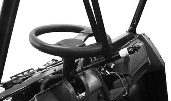
NOTE: All measurements and adjustments must be made with the vehicle unloaded, steering rack aligned with marks, steering wheel as shown at mid tilt and both wheels straight.
PR087A

MOD162
Mark the centerline of the front tires at the front and rear of the tire; then using a tape measure, measure and record the distance between the marks at the front and rear. The front measurement should be approximately 3-6 mm (1/8-1/4 in.) greater than the rear measurement (toe-out).
MOD066A
To adjust the wheel alignment, use the following procedure:
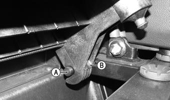
1.Using an open-end wrench to hold the tie rod ends (A), loosen the right-side and left-side jam nuts (B).
MOD196
CAUTION
Always use a wrench to hold the tie rod ends when loosening or tightening the jam nuts or damage to the boots could occur.
2.Turn the left-side and right-side tie rods (C) in equal increments to achieve the proper toe-out; then tighten the jam nuts securely. 3.Check steering for free operation (full-left/fullright).
Hood
REMOVING 1.Open the hood by turning the two 1/4-turn locks at the rear of the hood.

MOD008A
2.Remove the hood assembly. CLEANING AND INSPECTING 1.Clean all hood components with soap and water. 2.Inspect the hood for cracks. 3.Inspect for any missing decals. INSTALLING Place the hood into position on the vehicle making sure the front tabs are in place; then secure the hood with the 1/4-turn locks.
MOD044A
Upper Hood
REMOVING 1.Remove the hood; then remove the mid/upper dashboard; then the cap screws indicated
MOD044F
2.Remove the cap screws located next to each cup holder; then the cap screws in the middle; then remove mid/upper dash.
MOD251
MOD252
Front Fascia/Grille
Grille (A) Fascia (B)
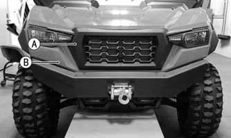
MOD013A
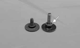
REMOVING 1.Remove the hood; then the two T30 cap screws securing the grille and front fenders. NOTE: Take note of the higher shoulder and longer thread for fastening through multiple panels.
MOD044C MOD133A
2.There are four cap screws per side that secure the bottom of the front fascia. 3.Remove the three T20 cap screws securing the outer front of the fascia; then remove them from the opposite side.

MOD134A

MOD140A
4.Remove the two T30 shouldered cap screws from the center of the front fascia; then remove the front fascia.
MOD140A

MOD136
INSTALLING 1.Place the front fascia into position and secure the two
T30 shouldered cap screws.
MOD140A
2..Install the two T20 cap screws through the (A) fender, (B) fender flare, and headlight bracket (not identified) into (C) front fascia/grille; then install the remaining T20 cap screw securing the front fascia to the lower grille. Repeat for opposite side.
MOD138A
MOD135A
5.Install the upper grille and tighten the two T30 cap screws; then install the hood and secure the 1/4-turn locks.
MOD044C
MOD008A
REMOVING 1.Remove the two cap screws located below the front tow hooks.

MOD509
2.Remove the two cap screws behind each tow hook and then remove the tow hooks.

MOD510
3.Remove the lower fascia-to-grille cap screw on each side.
MOD511
INSTALLING 1.Position the lower fascia into place; then install the lower fascia to grille cap screw on each side.
MOD511
2.Position the tow hooks into place; then install the two cap screws behind each tow hook. Tighten to 20 ft-lb (27.2 N-m).
MOD510
3.Install the two cap screws located below the front tow hooks.
MOD509
Front Fenders/Fender Flares
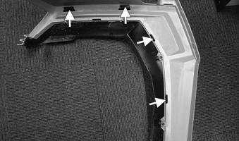
Removing the fender is recommended to remove the fender flare REMOVING 1.Remove the hood, upper hood and mid/upper dashboard. Located in the front of the inner fender, remove the two cap screws securing the fender, fender flare and grille to the headlight bracket.
MODC056
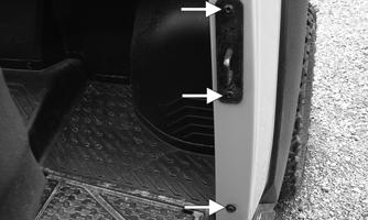
2.Remove the three shouldered cap screws from the top of the side cover and the two shouldered cap screws from the bottom of the side cover.
MOD262
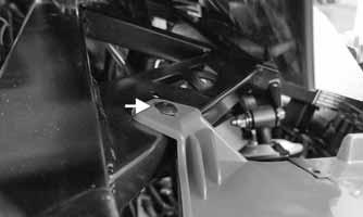
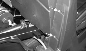
3.Gently pull on the front portion of the side panel; then remove the cap screw securing the fender to the frame. NOTE: A 1/4-in. driver bit is recommended to access this cap screw. More side panel cap screws will need to be removed to make room for a larger tool.

MOD142
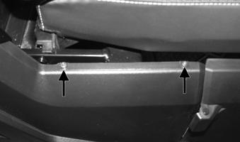
4.Remove the four cap screws from the inner fender.
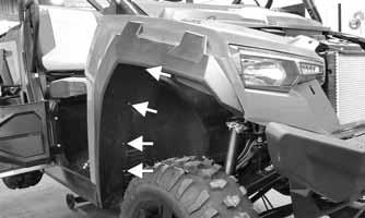
MOD137A
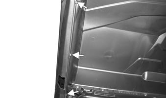
5.Remove the three cap screws indicated.
MOD592
6.Remove the two remaining cap screws on the top portion of the fender; then remove fender. If fender flare removal is desired, continue to step 7.
MOD150A
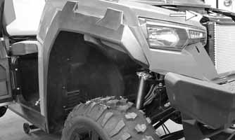
MOD607
7.With the fender removed from the vehicle, remove the four cap screws on the inside of the fender; then remove the fender flare from fender taking note of the four tabs on the fender flare.

MODC065
MODC065A
INSTALLING If installing fender flare, start at step 1. If installing fender, start at step 2. 1.With the fender removed from the vehicle, install the fender flare onto the fender taking note of the four tabs on the fender flare; then install the four cap screws to secure fender flare to fender.
MODC065A
MODC065
2.Place the fender into position; then install the two cap screws on the top portion of the fender.
MOD150A
MOD607
3.Install the three cap screws indicated.
MOD592
4. Install the four cap screws in the inner fender.
MOD137A
5.Gently pull on the front portion of the side panel; then install the cap screw securing the fender to the frame. NOTE: A 1/4-in. driver bit is recommended to access this cap screw. More side panel cap screws will need to be removed to make room for a larger tool.
MOD142
6.Install the three shouldered cap screws from the top of the side cover and the two shouldered cap screws from the bottom of the side cover.
MOD262
7.Located in the front of the inner fender, install the two cap screws securing the fender, fender flare and grille to the headlight bracket. Install the upper hood, mid/upper dashboard and hood; then adjust doors as needed.
MODC056
Side Panels
REMOVING 1.Tilt the cargo box into the up position; then remove the rear inner fender; then remove the cap screws behind the rear ROPS mounting point.
MOD190
2.Remove the three cap screws from inside the behind seat storage.
MOD191
3.Remove the four cap screws securing the door hinge and remove the door hinge; then remove the remaining cap screws securing the side panel; then remove the side panel.

MOD595
MOD192
INSTALLING 1.Position the cargo box into the up position; then reinstall the cap screws behind the rear ROPS mounting point.
MOD190
2.Reinstall the three cap screws from inside the behind-the-seat storage box panel.
MOD191
3.Position the door hinge into place; then reinstall the four cap screws securing the door hinge; then reinstall the remaining cap screws securing the side panel; then reinstall the rear inner fender.
MOD595
MOD192
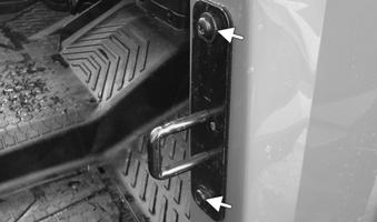
ADJUSTING DOORS
1.Door adjustment is accomplished by loosening the striker plate cap screws; then moving the striker plate up, down, in or out on the slotted holes. When desired latching/unlatching is obtained, tighten cap screws.
MOD279
Roof (Optional)
REMOVING/INSTALLING 1.Remove the cap screws and lock nuts securing the clamps at the rear of the roof. Account for the washers and the lock nuts. Discard lock nuts. Inspect cap screws and replace if damaged.
MOD689
2.Remove the cap screws and lock nuts at the front of the roof. Account for the washers and the lock nuts.
Remove the roof. Discard lock nuts. Inspect cap screws and replace if damaged.


MOD691
MOD692
3. Position roof onto the ROPS of the vehicle; then hook the rear brackets under the rear ROPS tube; then loosely secure the four rear brackets to the rear of the hardtop using eight cap screws, eight washers, and eight new lock nuts. The washers should be on the top of the roof. Finger tighten only at this time. 4. Loosely secure the front of the hardtop to the
ROPS using four cap screws, four washers, and four new lock nuts. The washers should be on the outside of the roof. 5. Tighten all hardware securely.
Front Bumper (Optional)
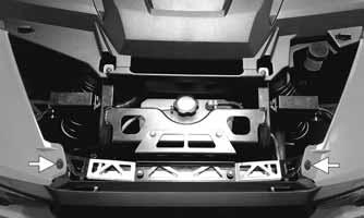
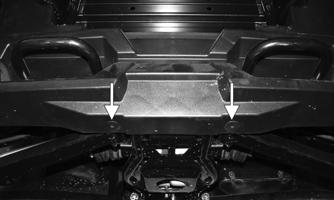
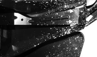
REMOVING/INSTALLING 1.Remove the two cap screws and lock nuts per side on the lower portion of the front bumper. Note the location of the spacers. Discard lock nuts. Inspect cap screws and replace if damaged.

MOD686
MOD687
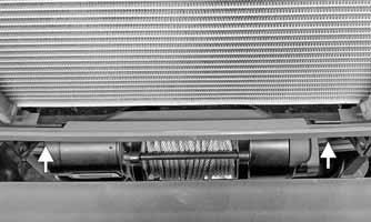
2.Remove the hook on the winch cable. Remove the two cap screws securing the winch fairlead; then remove the winch fairlead; then remove the four outer cap screws securing the bumper to the frame; then remove the bumper from the vehicle.
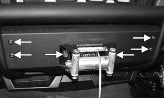
MOD688
3.Position the bumper into place; then install the four outer cap screws securing the bumper to the frame; then position the winch fairlead into place with the cable through the fairlead; then install the two cap screws securing the winch fairlead; then install the hook to the winch cable. Finger tighten only at this time. 4.Install the two cap screws, spacers and new lock nuts per side on the lower portion of the front bumper.
Tighten all fasteners securely.
Rear Bumper (Optional)
REMOVING/INSTALLING 1.Remove the four cap screws and lock nuts; then remove bumper. Discard lock nuts. Inspect cap screws and replace if damaged.
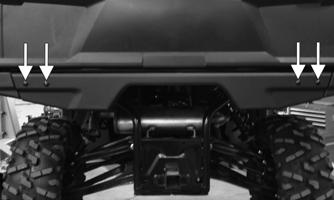
MOD684
2.Remove the four cap screws and two lock nuts per bumper bracket; then remove bumper brackets. Discard lock nuts. Inspect cap screws and replace if damaged.

MOD685
3.Install the four cap screws and two new lock nuts per bumper bracket. Finger tighten only at this time. 4.Position the bumper into place; then install the four cap screws and new lock nuts; then tighten all hardware securely.
Floor
REMOVING 1.Remove the seats, behind-the-seat storage box panel, side panels, and seat base. 2.Remove the three fasteners securing the splash panel on each side.
MOD592
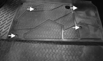
3.Remove the six fasteners on the occupant side securing the splash panel to floor.
MOD287
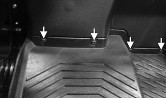
MOD288
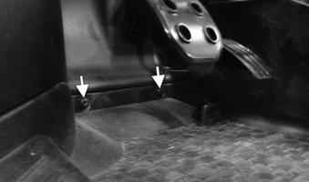
4.Remove the two cap screws located near the front tires securing the splash panel to floor on each side.
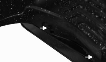
MOD289A
5.Remove the one cap screw located near the rearmost corner of the floor on each side.
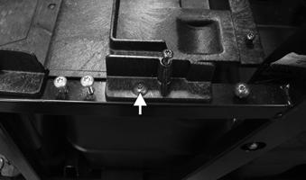
MOD290
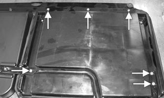
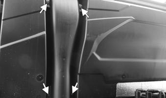
6.Remove the seven cap screws securing the floor to frame.
MOD291
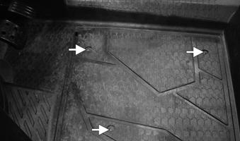
MOD292
7.Gently lift the rear of the floor up and lift the floor out of the vehicle. CLEANING AND INSPECTING 1.Clean the floor with soap and water. 2.Inspect the floor for cracks or holes. INSTALLING 1.Place the front of the floor into position in the vehicle first; then lower the rear; then fasten the seven cap screws securing the floor to frame.
MOD291
MOD292
2.Install the one cap screw located near the rearmost corner of the floor on each side.
MOD290
3.Install the two cap screws located near the front tires securing the splash panel to floor on each side.
MOD289A
4.Install the six fasteners on the occupant side securing the splash panel to floor.
MOD287
MOD288
5.Install the three fasteners securing the splash panel on each side
MOD592
6.Install the seats, behind-the-seat storage box panel, side panels, and seat base. Adjust doors as needed.
Dashboard (Mid/Upper)
REMOVING 1.Disconnect the battery; then remove the cap screws indicated, taking note of the different fastener types in the different locations.

MODC059A

MODC060

MOD146B
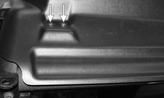
3.Gently lift the mid/upper dashboard above the cup holders on each side. Take note of the tabs on each side that must be lifted vertically at an angle.
MODC061
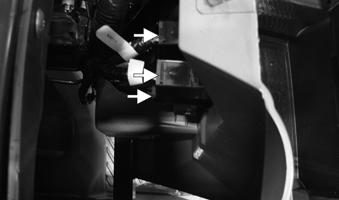
4.From behind the dashboard, disconnect the LCD gauge (A), and DC power outlets (B)(C). Note the orientation of the connectors for installing purposes; then remove the mid/upper dashboard.

MOD594A
INSTALLING 1.From behind the dashboard, connect the LCD gauge (A), and DC power outlets (B)(C).
MOD594A
2.Gently position the dashboard, taking note of the tabs on each side that must be positioned at an angle; then place dashboard over cup holders.

MODC061A
3.Install the cap screws indicated, taking note of the different fastener types in the different locations; then connect the battery.
MODC059
MODC060
MOD146B
Dashboard (Lower)
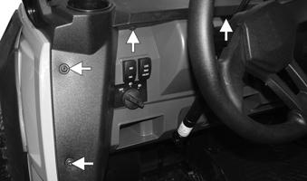
REMOVING 1.Remove the mid/upper dashboard; then remove the three cap screws on each fender.
MOD592
CAUTION
When removing the lower steering adjuster mount, the steering wheel tilt assembly will be unsecured and could drop causing injury. Hold the steering wheel tilt assembly while removing the lower steering adjuster cap screw to prevent this.
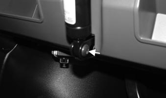
2.Remove the lower steering adjuster cap screw. With a suitable strap secure the steering wheel tilt assembly up and out of the way.
MOD263
MOD264A
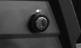
3.Remove the key switch locking nut by turning counterclockwise; then push the key switch through hole to clear the lower dashboard; then disconnect the electrical connectors on the left side of the dashboard.
MOD266
MOD265
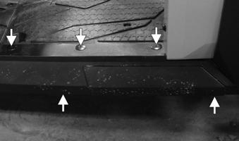
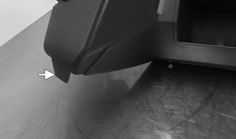
4.Remove the five cap screws along the bottom of the lower dashboard; then remove the lower dashboard taking note of the tabs on each side of the lower dashboard.

MOD268A MOD267
INSTALLING 1.Position the lower dashboard into place taking note of the tabs on each side of the lower dashboard.
Install the five cap screws along the bottom of the lower dashboard.
MOD267
MOD268A
2.Reinstall the key switch into the key switch cut out; then secure by turning the locking nut clockwise; then reconnect the electrical connectors on the left side of the dash. NOTE: The 4WD/2WD switch should be installed in the outermost switch slot on the left side of the dash and plugged into the connector that has white/green, black, and orange/gray wires. The LOCK/UNLOCK switch should be installed in the innermost switch slot on the left side of the dash and plugged into the connector that has yellow/orange, black, and orange/gray wires.

MOD266A
MOD265
3.Remove the suitable strap securing the steering wheel tilt assembly out of the way; then reinstall the lower steering adjuster cap screw. Tighten to 6 ft-lb (8.2 N-m).
MOD264A
MOD263
4.Reinstall the three cap screws on each fender; then install the mid/upper dashboard; then adjust doors as needed.
MOD592
Splash Panel
REMOVING 1.Remove the mid/upper dashboard, lower dashboard, side panels, seats, seat base, EPS, lower steering adjuster cap screw, and floor. 2.Disconnect the master brake cylinder, throttle cable, and shift cable. 3.Remove the five cap screws along the top of the splash panel; then remove the splash panel from the bottom.

MOD311

MOD312
INSTALLING 1.Position the splash panel into place; then install the five cap screws along the top of the splash panel.
MOD311
MOD312
2.Connect the master brake cylinder, throttle cable, and shift cable 3.Install the floor, lower steering adjuster cap screw,
EPS, seat base, seats, side panels, lower dashboard, and mid/upper dashboard.
Skid Plates
REMOVING 1.Remove the body screws securing the skid plates to the underside of the frame. 2.Remove the skid plates. INSTALLING 1.Place the skid plates into position on the underside of the frame. 2.Install the body screws. Tighten to 6 ft-lb (8.2 N-m).
Muffler
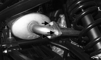
REMOVING 1.Remove the three cap screws and lock nuts at the muffler/exhaust pipe juncture. Discard lock nuts.
Inspect cap screws and replace if damaged.
MOD231
2.Lift the muffler assembly upward to clear the three holders underneath the muffler assembly.
MOD232
INSPECTING 1.Inspect muffler externally for cracks, holes, and dents. 2.Inspect the muffler internally by shaking the muffler back and forth and listening for rattles or loose debris inside the muffler. NOTE: For additional details on cleaning the muffler/ spark arrester, see Periodic Maintenance/Tune-Up. INSTALLING 1.Place the muffler onto the three holders and push into position. 2.With a new gasket installed, secure the muffler to the exhaust pipe with the three cap screws and new lock nuts. Tighten to 16 ft-lb (21.8 N-m).
Cargo Box
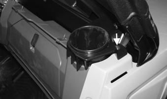
REMOVING 1.Raise the cargo box; then disconnect the electrical connection near the passenger-side cargo box pivot point.
MOD222
CAUTION
When the lift support is detached from cargo box, the box can drop with force. Take care when operating the box without lift support.
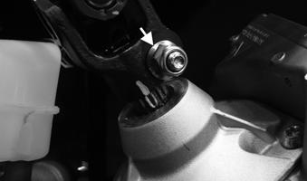
2.Remove the nut securing the upper lift support bolt; then with the cargo box secured in place, remove the bolt.

MOD611
3.Unfasten clip from lower lift support; then remove clip.
MOD223
4.Remove lift support from mounting; then carefully lower the cargo box to the down position.
MOD224
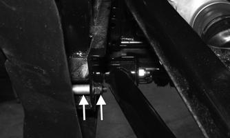
5.Remove the two cap screws and nuts on the hinge points.
MOD608
6.With the help of an assistant or an adequate lift, remove the cargo box from the vehicle. The cargo box tilt lever will need to be released.
CLEANING AND INSPECTING 1.Clean all cargo box components with soap and water. 2.Inspect the cargo box for cracks, tears, and loose hardware. 3.Inspect the welds of the cargo box frame for cracking or bending. 4.Inspect the cargo box gate latches for smooth operation. INSTALLING 1.Lightly grease the hinge points; then with the help of an assistant or an adequate lift, set the cargo box into position on the frame; then position the two hinge points between the cargo box and frame. 2.Align the holes in the hinge points with the holes in the cargo box; then install the two cap screws and nuts Tighten to 30 ft-lb (40.8 N-m). 3.Raise the cargo box; then connect the lift support to the lower mounting, and secure the clip on the lower lift support; then install the cap screw and nut for the upper lift support, and tighten to 10 ft-lb (13.6 N-m). 4.Connect the electrical connection near the passenger side cargo box pivot point; then lower the cargo box and lock into position.
REMOVING/INSTALLING PASSENGER SEAT BOTTOM 1.To remove the passenger seat bottom, raise the front of the seat and unhook both of the “C” channels of the seat bottom (B) out of the mounting pegs (A).
DISASSEMBLING 1.Remove the six cap screws securing the passenger seat backrest to the passenger seat backrest frame; then remove the passenger seat backrest from the passenger seat backrest frame.
MOD248
2.Install the seat bottom by hooking both of the “C” channels of the seat bottom into the mounting pegs (A). PASSENGER SEAT BACKREST REMOVING 1.Unlatch the passenger seat backrest; then fold down.
Unhook both of the tubes of the seat backrest (A) out of the “C” channels (B)

MOD121A MOD521
2.Remove the five flange nuts securing the passenger seat backrest to the passenger seat backrest frame; then remove the passenger seat backrest from the passenger seat backrest frame.
MOD609
ASSEMBLING 1.Position the passenger seat backrest to the passenger seat backrest frame; then install the six cap screws securing the passenger seat backrest to the passenger seat backrest frame. Tighten to 2 ft-lb (2.7 N-m).
MOD226 MOD521
2.Position the center passenger seat back to the passenger seat backrest frame; then install the five flange nuts securing the center passenger seat back to the passenger seat backrest frame. Tighten to 4 ft-lb (5.4
N-m).

MOD609
INSTALLING 1.Install the seat backrest by hooking both of the tubes of the seat backrest (A) into the “C” channels (B).
Fold up; then close the seat backrest latch.
MOD227
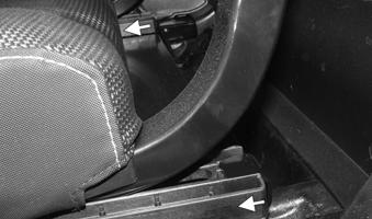
2.Lift the seat adjustment lever; then move the seat assembly toward the front of the vehicle to clear the rear mounting channel.
MOD226


MOD165
DRIVER SEAT REMOVING 1.Remove the six cap screws from underneath the driver seat rails.
MOD228
DISASSEMBLING 1.Remove the four cap screws securing the seat bottom to the seat assembly; then remove the seat bottom from the seat assembly.
MOD523
2.Remove the four cap screws securing the seat backrest to the seat assembly; then remove the seat backrest from the seat assembly.

MOD524

ASSEMBLING 1.Position the seat bottom to the seat assembly; then install the four cap screws securing the seat bottom to the seat assembly. Tighten to 2 ft-lb (2.7 N-m).
MOD228A
2.Install the six cap screws underneath the driver seat rails. Tighten to 2 ft-lb (2.7 N-m).
MOD523
2.Position the seat backrest to the seat assembly; then install the four cap screws securing the seat backrest to the seat assembly. Torque to 2 ft-lb (2.7 N-m).
MOD524
INSTALLING 1.Install the seat assembly by lifting up on the seat adjustment lever; then move the seat assembly toward the rear of the vehicle to hook into the rear mounting channels.
MOD227
Behind-the-Seat Storage Box Panel
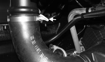
REMOVING 1.Remove the seats; then both rear inner fenders; then both side panels. 2.Remove the four cap screws and hose clamp for the
CVT air inlet snorkel.
MOD281
3.Remove the 11 cap screws securing the passenger seat backrest hinge; then remove the passenger seat backrest hinge.
MOD280A
4.Remove the two cap screws on each seat belt guide; then remove seat belt guides; then disconnect the seat belt electrical connector.
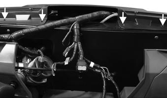
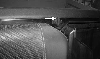
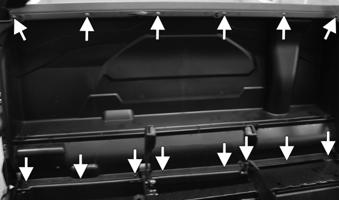
7.Remove the six cap screws securing the behind-theseat storage box panel; then remove the eight cap screws securing the behind-the-seat storage box panel to the floor; then remove the behind-the-seat storage box panel. NOTE: When removing the behind-the-seat storage box panel, it might be necessary to gently pull down on the top of the panel to clear the metal channel that connects the left and right rear ROPS.

MOD282
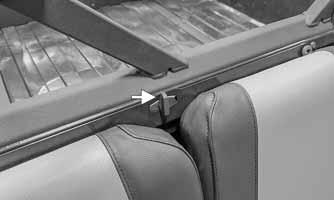
5.Remove the cap screw on each of the outer portions of the behind-the-seat storage box panel.

MOD610
INSTALLING 1.Gently position the behind-the-seat storage box panel into position; then reinstall the six cap screws on the top of the panel; then install the eight cap screws securing the behind-the-seat storage box panel to the floor.
MOD283
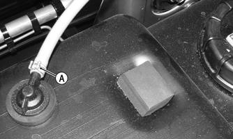
6.Disconnect the two electrical connections to the
ECU (A) that is located in front of the engine air filter.

MOD610
2.Reinstall the cap screw on each of the outer portions of the behind-the-seat storage box panel.

MOD283
3.Reinstall both seat belt guides; then reinstall the two cap screws on each seat belt guide; then connect the seat belt electrical connector.
MOD282
4.Reinstall the passenger seat back hinge; then reinstall the 11 cap screws securing the passenger seat back hinge.
MOD280A
5.Reinstall the four cap screws and hose clamp for the
CVT air inlet snorkel.
MOD593
7.Reinstall the seats; then both side panels; then both rear inner fenders.
Seat Base
REMOVING 1.Remove the seats; then remove the rear inner fenders and side panels; then remove the behind-the-seat storage box panel. 2.Remove the 12 cap screws securing the seat base; then remove the seat base.

MOD281
6.Reconnect the two electrical connectors to the ECU (A).
MOD285
INSTALLING 1.Position the seat base back into position; then secure using 12 cap screws.
MOD285
2.Reinstall the behind-the-seat storage box panel; then reinstall the side panels and rear inner fenders; then reinstall the seats.
Troubleshooting
Problem: Handling too heavy or stiff Condition
Remedy
1. Front wheel alignment incorrect 2. Steering shaft binding 3. Tire inflation pressure incorrect 4. Tie rod ends seizing 5. U-joints seized 6. EPS not working
Problem: Steering oscillation Condition
1.Adjust alignment 2.Lubricate/replace steering shaft 3.Adjust pressure 4.Replace tie rod ends 5.Replace U-joints 6.Diagnose EPS
Remedy
1. Tires inflated unequally 2. Wheel(s) bent 3. Wheel hub studs loose — missing 4. Wheel hub bearing worn — damaged 5. Tie rod ends worn — loose 6. Tires defective — incorrect 7. A-arm bushings damaged 8. Bolts — nuts (frame) loose 1.Adjust pressure 2.Replace wheel(s) 3.Tighten — replace wheel studs 4.Replace bearing 5.Replace — tighten tie rod ends 6.Replace tires 7.Replace bushings 8.Tighten bolts — nuts
Problem: Steering pulling to one side Condition Remedy
1. Tires inflated unequally 1.Adjust pressure 2. Front wheel alignment incorrect 2.Adjust alignment 3. Wheel hub bearings worn — broken 3.Replace bearings 4. Frame distorted 4.Repair — replace frame 5. Shock absorber defective 5.Replace shock absorber
Problem: Steering impaired Condition Remedy
1. Tire pressure too high 1.Adjust pressure 2. Steering linkage worn 2.Replace linkage 3. Cap screws (suspension system) loose 3.Tighten cap screws
Problem: Tire wear rapid or uneven Condition Remedy
1. Wheel hub bearings worn — loose 1.Replace bearings 2. Front wheel alignment incorrect 2.Adjust alignment
Problem: Steering noise Condition Remedy
1. Caps screws — nuts loose 1.Tighten cap screws — nuts 2. Wheel hub bearings broken — damaged 2.Replace bearings 3. Lubrication inadequate 3.Lubricate appropriate components
Problem: Rear wheel oscillation Condition Remedy
1. Rear wheel hub bearings worn — loose 1.Replace bearings 2. Tires defective — incorrect 2.Replace tires 3. Wheel rim distorted 3.Replace rim 4. Wheel hub studs loose — missing 4.Tighten — replace wheel studs 5. Rear suspension arm-related bushing worn 5.Replace bushing 6. Rear shock absorber damaged 6.Replace shock absorber 7. Rear suspension arm nut loose 7.Tighten nut