15 minute read
Suspension

The following suspension system components should be inspected periodically to ensure proper operation:
A.Shock absorber rods bent, pitted, or damaged.
B.Rubber damper cracked, broken, or missing.
C.Shock absorber body damaged, punctured, or leaking.
D.Shock absorber eyelets broken, bent, or cracked.
E.Shock absorber eyelet bushings worn, deteriorated, cracked, or missing.
F.Shock absorber spring broken or sagging.
G.Sway bar mountings tight and bushings secure. SPECIAL TOOL A special tool must be available to the technician when performing service procedures in this section. Refer to the current Special Tools Catalog for the appropriate tool description. NOTE: When indicated for use, each special tool will be identified by its specific name, as shown in the chart below, and capitalized.
Description p/n
Shock Spring Spanner Wrench 3441-139
NOTE: Special tools are available from the Service Department.
Shock Absorbers
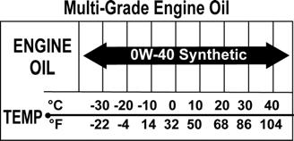
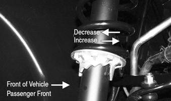
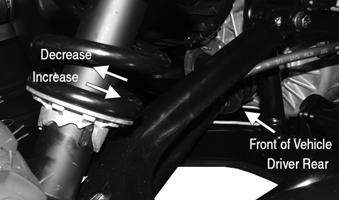
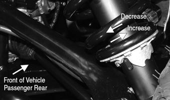
Each shock absorber should be visibly checked weekly for excessive fluid leakage (some seal leakage may be observed but it does not indicate the shock is in need of replacement), cracks or breaks in the lower case, or a bent shock rod. If any one of these conditions is detected, replacement is necessary. NOTE: When the vehicle is operated in extremely cold weather (-23° C/-10° F or colder), a small amount of leakage may be present. Unless the leakage is excessive, replacement is not necessary. This vehicle is equipped with adjustable shock assemblies in the front and rear to allow for different driving and loading conditions. The front shock absorbers have an adjustment sleeve with five preload adjustment positions that can be turned with the spanner wrench to increase or decrease coil spring tension.
MOD186
NOTE: Before attempting to adjust suspension, clean dirt and debris from the sleeve and remove load from the suspension; then use the spanner wrench to adjust the sleeve to the desired position. To adjust the spring force on these shock absorbers, rotate the preload adjustment sleeve with a suitable spanner wrench until desired spring tension is achieved.
Position Spring Force Setting Load
1 Soft Light 2
3
4
5 Stronger Stiff Heavy

MOD178
MOD179
MOD180
MOD181
REMOVING SHOCK 1.Secure the vehicle on a support stand to elevate the wheels and to release load on the suspension.
2.Remove the upper and lower mounting cap screws and lock nuts. Discard lock nuts. Inspect cap screws and replace if damaged.
! WARNING
Make sure the vehicle is solidly supported on the support stand to avoid injury.
FRONT

MOD333
FRONT
MOD334
REAR
MODC070
REMOVING SPRING 1.Remove the shock; then use a suitable spring compressor, compress the spring and remove the retainer ring. 2.Carefully release the spring pressure and remove the spring. Account for the spring retainer.
INSTALLING SPRING 1.Use a suitable spring compressor, compress the spring and install the retainer ring. 2.Carefully release the spring pressure and remove the suitable spring compressor tool.
CLEANING AND INSPECTING 1.Clean all shock absorber components in parts-cleaning solvent. 2.Inspect each shock rod for nicks, pits, rust, bends, and oily residue. 3.Inspect all springs, spring retainers, shock rods, sleeves, bushings, shock bodies, and eyelets for cracks, leaks, and bends.
! WARNING
Shock absorber springs are under high compression loads. Do not attempt to remove springs without an adequate spring compressor. Severe injury could result.
! WARNING
Shock absorber springs are under high compression loads. Do not attempt to install springs without an adequate spring compressor. Severe injury could result.
INSTALLING 1.Install the shock absorbers with two cap screws and new lock nuts. Tighten to 45 ft-lb (61.2 N-m). 2.Remove the vehicle from the support stand.
Front A-Arms
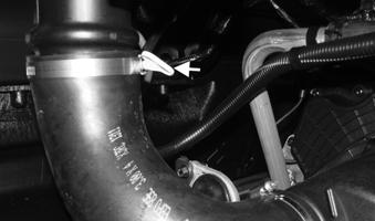
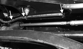
REMOVING 1.Remove the hubs (see Drive and Brake Systems section). 2.Remove the brake hose clamps from the upper
A-arm; then cut the cable tie from the A-arm. Note the location of the white marks on the brake line for installation purposes.
MOD501
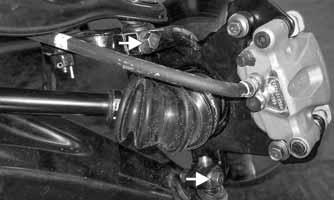
3.Remove the cotter pin and castle nut securing the tie rod end to the knuckle; then remove the tie rod end from the knuckle.
MOD129
4.Remove the cap screws securing the ball joints to the knuckle.
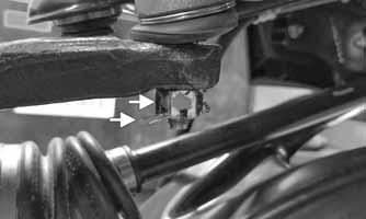
CAUTION
Support the knuckle when removing the cap screws or damage to the threads will occur.
MOD130
5.Tap the ball joints out of the knuckle; then remove the knuckle. 6.Remove the lower shock absorber eyelet from the upper A-arm.

MOD334
NOTE: When removing the lower A-arm, removal of the front fascia is also required. 7.Remove the cap screws securing the A-arms to the frame.
MOD335
MOD336
8.Remove the snap ring from the ball joint; then remove the ball joint from the A-arm.
MOD337
CLEANING AND INSPECTING 1.Clean all A-arm components in parts-cleaning solvent. 2.Clean the ball joint mounting hole of all residual
Loctite, grease, oil, or dirt for installing purposes. 3.Inspect the A-arm for bends, cracks, and worn bushings. 4.Inspect the ball joint mounting holes for cracks or damage. 5.Inspect the frame mounts for signs of damage, wear, or weldment damage. INSTALLING 1.Apply Loctite Primer “T” to the A-arm socket; then apply green Loctite #609 to the entire outside diameter of the ball joint. Install the ball joint into the
A-arm and secure with the snap ring. 2.Install the A-arm assemblies into the frame mounts and secure with the cap screws. Only finger-tighten at this time.
MOD336
MOD335
3.Route the brake hose along the upper A-arm. Secure with hose anchors and the clamp.
MOD501
4.Secure the lower eyelet of the shock absorber to the lower A-arm. Tighten nut to 45 ft-lb (61.2 N-m). 5.Secure the A-arm assemblies to the frame mounts (from step 2). Tighten the upper A-arm cap screws to 45 ft-lb (61.2 N-m) and the lower A-arm cap screws to 45 ft-lb (61.2 N-m). If removed, install the lower fascia. 6.Install the knuckle assembly onto the ball joints and secure with cap screws. Tighten to 45 ft-lb (61.2 N-m).
MOD130
7.Install the tie rod end and secure with the nut (coated with red Loctite #271). Tighten to 32 ft-lb (43.5 N-m); then install a new cotter pin and spread the pin to secure the nut. NOTE: During assembly, new cotter pins should be installed.
MOD129
8.Apply grease to the hub and drive axle splines; then install the hub (see Drive and Brake Systems section).
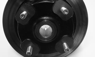
MOD328
9.Secure the brake caliper holder to the knuckle with two new “patch-lock” cap screws. Tighten to 45 ft-lb (61.2 N-m).
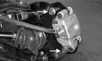
MOD130A
10.Install the wheels and using a crisscross pattern, tighten the wheel nuts in 20 ft-lb (27.2 N-m) increments to a final torque of 100 ft-lb (136 N-m). 11.Remove the vehicle from the support stand.
Sway Bar
REMOVING 1.With the vehicle in Park, secure the vehicle on a support stand to elevate the wheels.
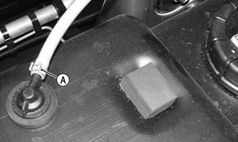
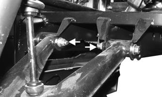
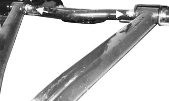
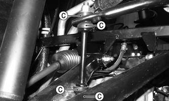
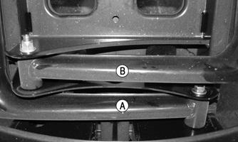
2.Using a wrench on the flat spot (A) of the sway bar link, remove at least one sway bar link lock nut (B) per side. Account for the four sway bar link bushings (C). Discard lock nuts.
! WARNING
Make sure the vehicle is solidly supported on the support stand to avoid injury.

MOD503
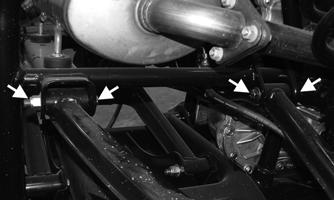
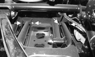
3.Remove the two cap screws per side securing the sway bar to the frame; then remove sway bar from frame.
MOD505
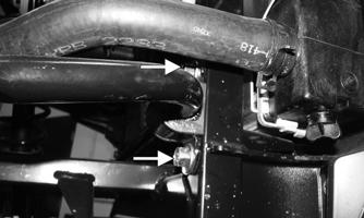
INSTALLING 1.Position the sway bar into the vehicle; then push the sway bar mount toward the center of the vehicle and lightly coat with grease on the sway bar where the sway bar mount will be; then position the sway bar mount to the mounting location and install the two cap screws securing the sway bar to the frame. Tighten to 20 ft-lb (27.2 N-m). Repeat for other side.

MOD506
MOD505
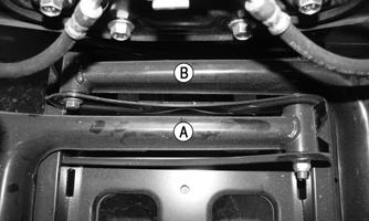
2.Position the sway bar link into the upper A-arms with the four bushings as shown; then using a wrench on the flat spot (A) of the sway bar link, install new sway bar link lock nuts (B). Tighten so there are 1-2 threads exposed on the upper sway bar link and 5-6 threads exposed on the lower sway bar link. Repeat for other side.
MOD504
MOD503
3.Remove the vehicle from the secure support stand.
Rear A-Arms
REMOVING 1.With the vehicle in Park, secure the vehicle on a support stand to elevate the wheels.
2.Remove the wheel; then remove the brake caliper; then remove the hub. 3.Remove the lower shock cap screw and lock nut; then secure the shock up and out the way with a suitable strap. 4.Remove the knuckle cap screws and lock nuts; then remove the knuckle; then position the half shaft away from the A-arms. 5.Remove the nylon strap and clamp securing the brake line underneath the upper A-arm; then remove the upper A-arm cap screws and lock nuts; then remove the upper A-arm. Discard lock nuts. Inspect cap screws and replace if damaged.
! WARNING
Make sure the vehicle is solidly supported on the support stand to avoid injury.

MOD371
MOD370
NOTE: When removing a lower A-arm it is required to lift the opposite lower A-arm in order to have access to the cap screws. This is best accomplished by removing the lower shock mount cap screw for the opposite A-arm and using a suitable strap to lift the A-arms.
MOD369
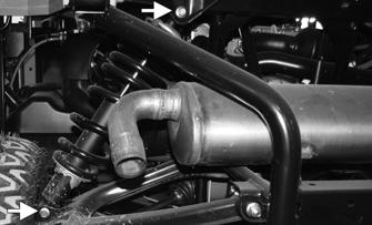
6.Remove the lower A-arm cap screws and lock nuts; then remove the lower A-arm. Discard lock nuts.
Inspect cap screws and replace if damaged.
MOD372
CLEANING AND INSPECTING 1.Clean all A-arm components in parts-cleaning solvent. 2.Inspect the A-arm for bends, cracks, and worn bushings. 3.Inspect the frame mounts for signs of damage, wear, or weldment damage. INSTALLING 1.Install the A-arm assemblies into the frame mounts and secure with the cap screws and new lock nuts.
Finger tighten only at this point.
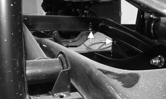
CAUTION
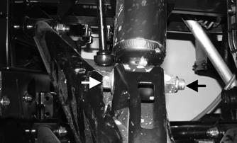
The lower rear A-arm bolts must be installed with the driver-side A-arm (A) cap screw threads toward the rear of the vehicle and the passenger-side A-arm (B) cap screw threads toward the front of the vehicle as shown. Failure to do so will result in suspension component damage.
MOD507
2.Slide the knuckle onto the drive axle and into position on the A-arms; then secure the knuckle to the
A-arms with cap screws and new lock nuts. Tighten to 45 ft-lb (61.2 N-m). 3.Tighten the hardware securing the A-arms to the frame mounts (from step 1) to 45 ft-lb (61.2 N-m). 4.Secure the lower shock mount to the A-arms with a cap screw and new lock nut. Tighten to 45 ft-lb (61.2 N-m). 5.Install the hub; then the brake caliper. 6.Install the wheels and using a crisscross pattern, tighten the wheel nuts in 20 ft-lb (27.2 N-m) increments to a final torque of 100 ft-lb (136 N-m). 7.Remove the vehicle from the support stand.
Rear Knuckles
CHECK FOR DAMAGED OR WORN BEARING, COLLAR AND BUSHINGS 1.Secure the vehicle on a support stand to elevate the wheel. 2.Turn wheel right and left to check for free-play. 3.If any free-play is present, replace the bearing, bushings and collar as applicable. REMOVING AND DISASSEMBLING 1.With the vehicle in Park, secure the vehicle on a support stand to elevate the wheel.
! WARNING
Make sure the vehicle is solidly supported on the support stand to avoid injury.
2.Remove the wheel; then remove the brake caliper; then remove the hub as described in the Hub/Brake
Disc section. 3.Remove the knuckle cap screws (A) and lock nuts (B); then remove the knuckle. Discard lock nuts (B).
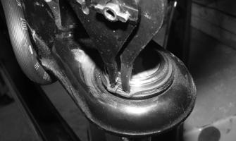
Inspect cap screws and replace if damaged. 4.If bearing (C) needs to be replaced: Remove the snap ring (D) securing the bearing in the knuckle; then press the bearing out of the knuckle. Discard bearing. 5.If bushings (E) need to be replaced: Remove dust seals (F), then push collar (G) out of upper knuckle bushings. Press the upper and lower bushings out of knuckle. Discard bushings and collar.
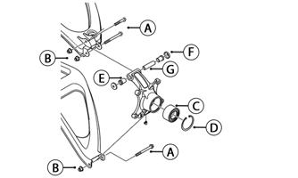
MODC079
CLEANING AND INSPECTING 1.Clean all knuckle components. 2.Inspect the knuckle for cracks and breaks. 3.If replacing bushings and bearings, inspect knuckle for galling of the bearing and bushing surface. ASSEMBLING AND INSTALLING 1.If a bearing needs to be replaced: Using a suitable press and driver, press a new bearing into the knuckle until firmly seated; then install the snap ring with the sharp edge away from the bearing. 2.If a bushing needs to be replaced: Using a suitable press and driver, press four new bushings into knuckle until contact is made with bushing flange.
Insert new collar and replace dust seal on the upper knuckle bushings. 3.Slide the knuckle onto the drive axle and into position on the A-arms; then secure the knuckle to the
A-arms with cap screws and new lock nuts. Tighten to 45 ft-lb (61.2 N-m). 4.Grease knuckles; clean dirt or debris from the Zerk before adding grease. Add grease to the Zerk until any trapped air or moisture is pushed out. 5.Install the hub; then install the brake caliper as described in the Hub/Brake Disc section. 6.Install the wheels and using a crisscross pattern, tighten the wheel nuts in 20 ft-lb (27.2 N-m) increments to a final torque of 100 ft-lb (136 N-m). 7.Remove the vehicle from the support stand.
TIRE SIZE
! WARNING
Use only approved tires when replacing tires. Failure to do so could result in unstable vehicle operation.
This vehicle is equipped with low-pressure tubeless tires of the size and type listed in the General Information section. Do not under any circumstances substitute tires of a different type or size.
TIRE INFLATION PRESSURE Front tire inflation pressure should be 82.7 kPa (12 psi) cold. Rear tire inflation pressure should be 97 kPa (14 psi) cold. Rear tire inflation pressure with cargo should be 110 kPa (16 psi) cold. REMOVING 1.Secure the vehicle on a support stand to elevate the wheels.
2.Remove the nuts securing the wheels; then remove the wheels. CLEANING AND INSPECTING 1.Clean the wheels and hubs with parts-cleaning solvent. 2.Clean the tires with soap and water. 3.Inspect each wheel for cracks, dents, or bends. 4.Inspect each tire for cuts, wear, missing lugs, and leaks. INSTALLING 1.Install each wheel on its hub and secure with the existing hardware. 2.Using a crisscross pattern, tighten the wheel nuts in 20 ft-lb (27.2 N-m) increments to a final torque of 100 ft-lb (136 N-m). CHECKING/INFLATING 1.Using an air pressure gauge, measure the air pressure in each tire. Adjust the air pressure as necessary to meet the recommended inflation pressure. 2.Inspect the tires for damage, wear, or punctures.
! WARNING
Always use the size and type of tires specified. Always maintain proper tire inflation pressure.
! WARNING
Do not mix tire tread patterns. Use the same pattern type on front and rear. Failure to heed warning could cause poor handling qualities of the vehicle and could cause excessive drive train damage not covered by warranty.
! WARNING
Make sure the vehicle is solidly supported on the support stand to avoid injury.
! WARNING
Do not operate the vehicle if tire damage exists.
NOTE: If repair is needed, follow the instructions found on the tire repair kit or remove the wheel and have it repaired professionally. NOTE: Be sure all tires are the specified size and have identical tread pattern.
Troubleshooting
Problem: Suspension too soft Condition Remedy
1. Spring preload incorrect 1.Adjust preload 2. Spring(s) weak 2.Replace spring(s) 3. Shock absorber damaged 3.Replace shock absorber 4. Shock absorbers too soft 4.Check/replace shock absorbers
Problem: Suspension too stiff Condition Remedy
1. Spring preload incorrect 1.Adjust preload 2. Shock absorbers too hard 2.Check/replace shock absorbers
Problem: Suspension noisy Condition Remedy
1. Cap screws (suspension system) loose 1.Tighten cap screws 2. Sway bar bushings worn 2.Replace sway bar bushings
Problem: Vehicle pulling or steering erratic Condition Remedy
1. Vehicle steering is erratic on dry, level surface 1.Check front wheel alignment and adjust if necessary (see Steering/Body/Controls — Front Wheel Alignment) 2. Vehicle pulls left or right on dry, level surface 2.Check air pressure in tires and adjust to specifications
Problem: Ride height is too low (<10 inches at center of frame to ground) Condition Remedy
1. Spring(s) weak 1.Replace spring(s) 2. Spring preload incorrect 2.Adjust preload 3. ROV/UTV overloaded 3.Remove weight from ROV/UTV 4. Tires not enough air pressure 4.Add the recommended amount of air to tires 5. Spring(s) broken 5.Replace spring(s)