43 minute read
Drive System

GENERAL INFORMATION Gear cases are 3.6:1.
NOTE: Never reuse a lock nut. Once a lock nut has been removed, it must be replaced with a new lock nut.
SPECIAL TOOLS A number of special tools must be available to the technician when performing service procedures in this section. Refer to the current Special Tools Catalog for the appropriate tool description. NOTE: When indicated for use, each special tool will be identified by its specific name, as shown in the chart below, and capitalized.
Description p/n
Backlash Measuring Tool (24-Spline Axle) 0544-010 CV Boot Clamp Tool Common Tool Internal Hex Socket Common Tool Pinion Gear/Shaft Removal Tool Common Tool Gear Case Seal Installer Tool 0444-273 Hub Retaining Wrench 0444-270
NOTE: Special tools are available from the Service Department.
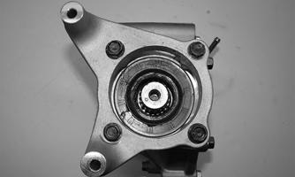
Front Drive Actuator
NOTE: The actuator is only serviceable as an assembly. NOTE: The actuator will operate only when the ignition switch is in the ON position. The front drive actuator is located on the right side of the front differential input housing. With the engine stopped and the ignition switch in the ON position, a momentary “whirring” sound can be heard each time the drive select switch is shifted. If no sound is heard, see Electrical System. If the actuator runs constantly or makes squealing or grinding sounds, the actuator must be replaced. REMOVING 1.Turn the ignition switch to the ON position; then select 2WD LOCK on the drive select switch.
Remove the drain plug from the bottom of the differential and allow the fluid to drain; then remove the seat and center floorboard kick panel. 2.Remove the air box and intake tube found below the center floorboard kick panel.

PK305
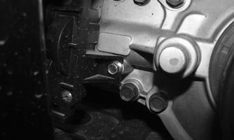
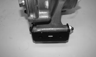
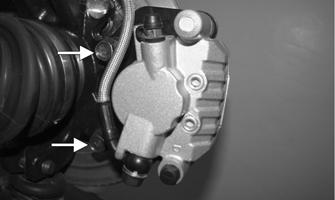
3.From the rear, remove the two cap screws securing the actuator to the differential and bracket.
PK306A
4.Remove the rubber access plug found toward the back side of the actuator; then remove the selector shaft circlip and spacer. Discard the circlip.
PK034A
PK035
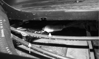
5.Remove the cable tie securing the actuator wiring
Note the location for assembly purposes. Disconnect the actuator connector. Remove the cap screw securing the coolant pipe bracket to the frame.
PK307A
PK308A
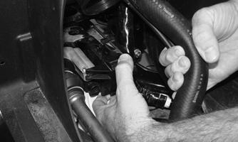
6.Loosen but do not remove the mounting cap screw at the front of the actuator. Pull the right side coolant hose out of the way; then slide the actuator to the rear to clear the slotted mounting tab and the selector shaft.
PK309
INSTALLING 1.Lubricate the O-rings on the actuator; then ensure all mounting surfaces are clean and free of debris. 2.Align the actuator with the selector shaft and slide it forward onto the shaft taking care to engage the cap screw in the slot of the front mounting tab.
PK309
3.While holding the actuator firmly forward, tighten the front cap screw to hold the actuator in place; then install but do not tighten the two remaining cap screws.
PK306A
4.Loosen the front cap screw; then tighten the cap screws on the driveshaft side.
NOTE: It is important to tighten this cap screw while the others are loose to ensure proper seating of the actuator.
5.Tighten the remaining cap screw; then connect the electrical plug to the main harness. Secure the wiring with a new cable tie, as noted in removal. 6.Install the spacer on the selector shaft; then secure using a new circlip. Ensure the circlip fully seats to the groove in the selector shaft. Install the rubber plug.
PK035
PK034A
7.Secure the coolant pipe bracket back onto the frame using a cap screw. Install the differential drain plug.
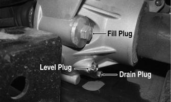
Remove the fill and oil level plugs. Add the recommended oil into the differential until fluid emerges from the oil level plug hole. Secure the fill and oil level plugs. 8.Turn the ignition switch to the ON position and check the operation by shifting the drive select switch several times. 9.Install and secure the center intake tube and air box assembly.
PK305A
10.Install the center floorboard kick panel and seat.
REMOVING 1.Remove the front belly panel. 2.Remove the drain plug and drain the gear lubricant into a drain pan; then install the plug and tighten to 45 in.-lb (5.1 N-m).
PK029A
3.Remove the hubs (see Hub in this section, steps 1-5). 4.Remove the center floorboard kick panel; then disconnect the front drive actuator connector from the main harness.
PK307A
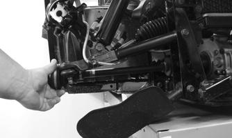
5.Remove the lower and upper ball joint cap screws taking care not to strip the threads on the ball joint shaft; then using a rubber mallet, tap the end of the axle and free it from the knuckle assembly.
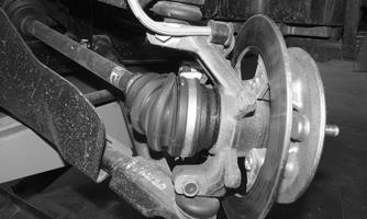
PK005
6.Pull the steering knuckle away from the axle.
PR222
7.Support the axle to prevent it from dropping or hanging.
8.Use a tie-down to hold the steering knuckle and brake caliper up and out of the way.
CAUTION
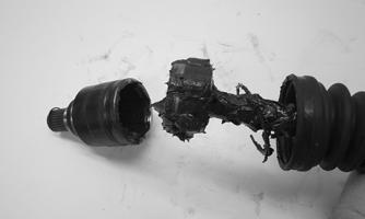
The axle must be supported. If the axle is allowed to drop or hang, damage to the inner CV joint may occur.

PK311
9.Position the axle horizontally and grasp the axle mid shaft; then push the axle slightly in toward the differential. Using a slide hammer type action, pull the axle out from the differential. Remove the axle from the differential. Repeat for the opposite side.
PK233A
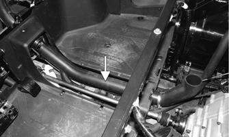
NOTE: The front right axle must be installed in its original location because it is designed with the splined differential lock ring toward the inside of the inner CV joint. 10.From below the frame, remove the lower mounting cap screws securing the forward differential bracket to the frame.

PK230A
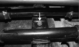
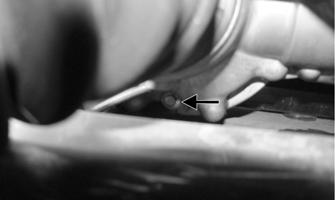
11.Remove the upper differential mounting cap screw and lock nut. Discard the lock nut.

PK231
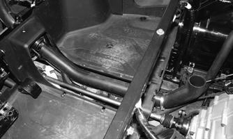
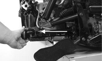
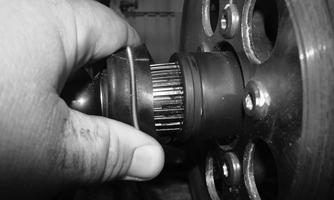
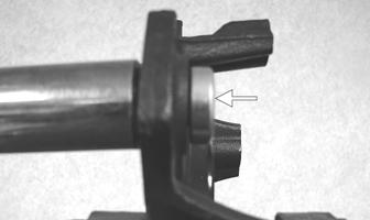
12.Slide the front propeller shaft boot back; then, while holding the shaft in place, slide the differential forward to disengage the splines. Account for the spring.
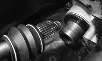
PK312
13.Protect the painted surface of the frame; then tilt the differential assembly on its left side. Remove through the front of the frame.

PK313
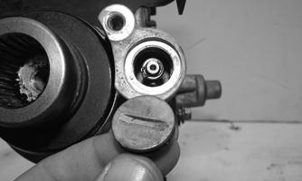
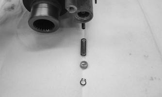
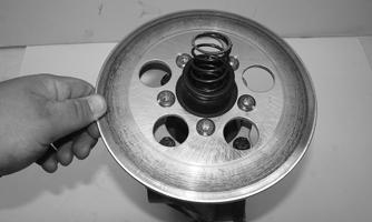
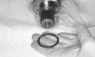
Disassembling Input Shaft 1.Remove the actuator (see Front Drive Actuator section). 2.Remove the slotted aluminum plug and account for the O-ring. Remove the differential locking shaft circlip. Account for the circlip, spring retainer, and spring. Note the orientation of these components for assembly purposes.
PK036
PK037
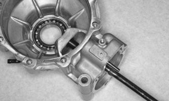
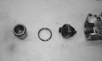
3.Noting the orientation of the actuator bracket, remove the three cap screws securing the input housing. Using a rubber a mallet to loosen the housing from the differential, remove the housing. Account for the dowel pin and gasket.

PK038A

PK039
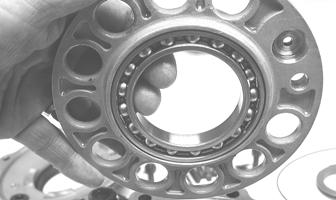
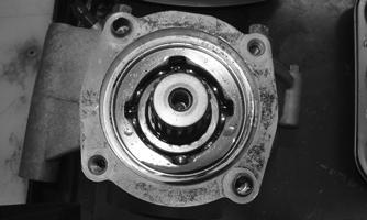
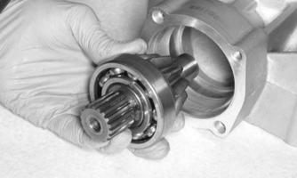
4.Remove the snap ring securing the input shaft; then slide it out of the housing.

PK040

PK041
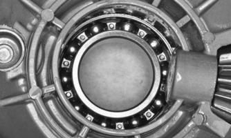
5.To gain access to the housing bearing, remove the seal and snap ring from the input shaft housing.
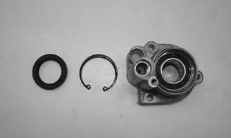
PK042
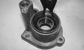
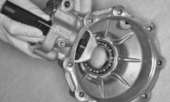
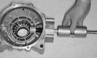
6.From the opposite side of the housing, use an appropriate sized bearing driver to press the bearing out of the housing.
PK043
Assembling Input Shaft 1.Using an appropriate sized bearing driver, press a new bearing into the input shaft housing. Secure the bearing with the existing snap ring, making sure the sharp edge of the snap ring faces toward the outside.
PK044 PK045
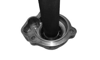
2.Install the input shaft seal, making sure it is fully seated in the housing.
GC014
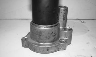
3.Grease the seal; then inspect and clean the sealing surface of the input shaft. Insert the input shaft into the bearing and secure with the snap ring.
PK041
PK046
4.With the dowel pin in place, set a new gasket into position and secure the pinion housing to the differential with the three cap screws.
PK038A
5.Install the differential shaft spring and spring retainer; then secure with a new circlip. Thread the plug into the housing.
PK037
PK036
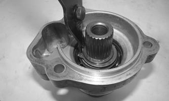
6.Install the actuator. Disassembling Differential Assembly NOTE: This procedure can be performed on a rear gear case. 1.Remove the input shaft housing (see Disassembling
Input Shaft in this section). Account for the slotted plug, circlip, spring cap, spring, fork/push rod assembly, and coupler.

PK205
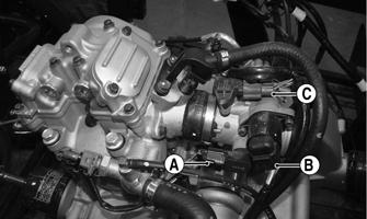
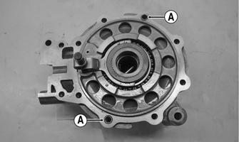
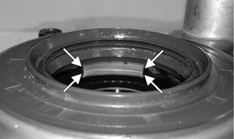
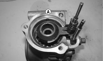
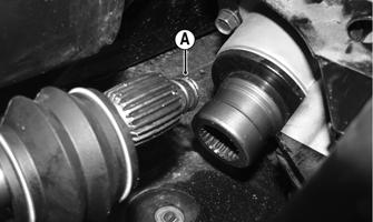
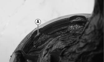
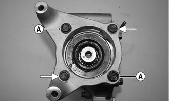
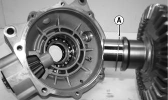
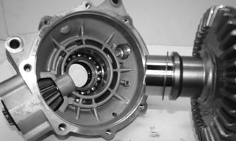
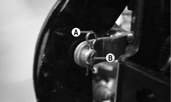
2.Using a criss-cross pattern, loosen and remove the cap screws securing the differential cover. 3.Using a plastic mallet, tap lightly to remove the differential cover. Account for a gasket and two dowel pins (A).
PK206A
NOTE: If the cover is difficult to remove, pry on the cover in more than one recessed location.
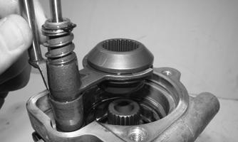
4.Remove the splined coupler, shifter fork, pin, and springs of the differential lock assembly and set aside. Note position of parts for assembling purposes.
PK207
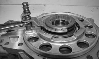
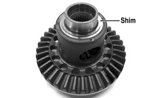
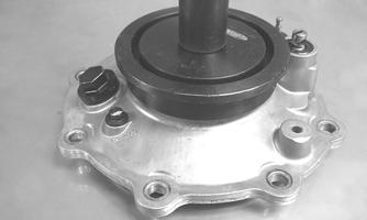
5.Remove the right differential bearing flange assembly and account for a shim. Mark the shim as rightside.
KX177

PK208A
6.Place the differential with the open side down; then lift the housing off the spider assembly. Account for shim(s) and mark as left-side.

PK209

KX181
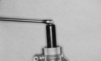
Disassembling Pinion Gear 1.Using the Internal Hex Socket, remove the lock collar securing the pinion bearing in the housing.

PK210
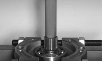
2.Using the Pinion Gear/Shaft Removal Tool and a hammer, remove the pinion gear from the gear case housing.

PK211
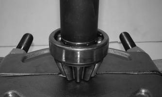
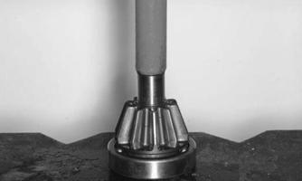
3.Place the pinion gear in a bearing puller or press blocks; then remove the pinion bearing using a press.
Account for a collar and a bearing.

PK212
4.Inspect the pinion gear needle bearing. Using a suitable bearing puller, remove the needle bearing.

PK216
PK217
5.Remove any reusable parts from the gear case housing; then discard the lock collar. Assembling Pinion Gear 1.Install a new needle bearing by using a suitable sized bearing driver against the outer race of the bearing.
PK218
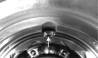
2. Place the pinion assembly in a bearing puller or press blocks; then install the bearing using a press. 3.Using a propane torch, heat the gear case housing to approximately 200° F (93° C); then install the pinion assembly. 4.Install a new lock collar and tighten to 125 ft-lb (169.5 N-m). Stake the collar into the gear case.
PK214
PK210
PK215A
Case-Side Shims (Backlash) p/n mm in. 3307-304 1.3 0.051 3307-305 1.4 0.055 3307-306 1.5 0.059 3307-307 1.6 0.063 3307-308 1.7 0.067
Cover-Side Shims (Ring Gear End-Play) p/n mm in.
3306-132 1.0 0.039 3306-133 1.1 0.042 3306-134 1.2 0.046 3306-135 1.3 0.051 3306-136 1.4 0.055 3306-137 1.5 0.059 3306-138 1.6 0.063 3306-139 1.7 0.067 It is very important to adjust bevel gears for the proper running tolerances. Gear life and gear noise are greatly affected by these tolerances; therefore, it is very important to properly adjust any gear set prior to final assembly. The following procedure can be used on both front differential or rear drive gear case. NOTE: All bearings must be installed in the gear case and the pinion properly installed before proceeding. Backlash NOTE: Always set backlash prior to any other shimming. 1.Install the existing shim or a 0.051-0.055-in. shim on the gear case side of the ring gear assembly.
GC031A
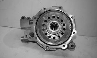
2.Install the ring gear with shim in the gear case; then while holding the pinion stationary, rock the ring gear forward and back to determine if any backlash exists. If no backlash exists, install a thicker shim and recheck.

PK208B
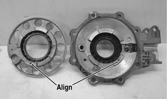
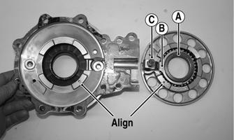
3.Install the bearing flange onto the gear case cover making sure the alignment/locating pin engages the locating hole in the cover; then make sure the bearing flange is completely seated in the cover.
PK219A

GC033A
4.Install the existing shim or a 0.063 in. shim on the cover side of the ring gear; then place the assembled gear case cover onto the gear case and secure with three cap screws. Tighten evenly using a crisscross pattern.
PK208A
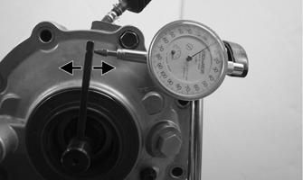
5.Place the appropriate Backlash Measuring Tool (24 spline axle) into the splines of the ring gear and install a dial indicator making sure it contacts the gauge at a 90° angle and on the index mark.

GC040

PK220A
6.Zero the dial indicator; then while holding the pinion stationary, rock the ring gear assembly forward and back and record the backlash. Backlash must be 0.002-0.010 in. If backlash is within specifications, proceed to Ring Gear End-Play. NOTE: If backlash is not within specifications, increase the case side shim thickness and decrease the cover side shim thickness. To decrease the backlash, decrease the case side shim thickness and increase the cover side shim thickness.
NOTE: Higher backlash settings usually result in quieter gear operation.
PK220B
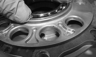
Ring Gear End-Play After correcting backlash, ring gear end-play can be adjusted. To adjust end-play, use the following procedure: 1.Secure the gear case in a holding fixture with the cover side up; then install a dial indicator contacting the ring gear axle flange.

PK221
2.Zero the dial indicator; then push the ring gear toward the dial indicator and release. End-play should be 0.004-0.008 in. 3.To increase end-play, decrease the cover side shim thickness. To decrease end-play, increase the cover side shim thickness.
NOTE: Once proper backlash and end play are established, the gear case can be assembled. Assembling Differential Assembly 1.With the pinion gear and new bearings installed, place the selected (backlash) shim on the gear case side of the ring gear with the chamfered side toward the ring gear; then install into gear case/differential housing.
GC031A
PK222
2.Place the selected (end-play) shim, chamfered side toward the gear (if applicable), onto the cover side of the ring gear.
PK208A
NOTE: The spider and ring gear assembly must be replaced as a complete unit. 3.Place the differential lock coupler (A) into the fork (B); then install the differential lock fork shaft (C) into the bearing flange. Ensure the alignment pin found in the bearing flange aligns with the recess in the differential cover. Place the cover onto the bearing flange.
PK223A
PK224
4.Verify the bearing flange is properly aligned with the different cover and fully seated. With the two dowel pins in place on the differential housing, place a new gasket into position.
PK225A

PK222A
5.Keeping the bearing flange pressed against the cover, install the assembly onto the differential housing.
While this is being performed, align the internal splines of the differential lock coupler to the external splines of the housing. Secure the cover to the housing with existing cap screws. Tighten evenly to 16.5 ft-lb (22.4 N-m). NOTE: Place the differential ID tag in the position shown.

PK226
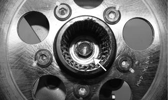
6.Install the two shift fork shafts with spring and 2WD/ 4WD coupler into the housing. Grease the splines; then engage the splines of the coupler to the splines of the pinion shaft.
PK227
7.With the dowel pin (A) in place, install a new gasket.
Place the input shaft housing with bracket onto the differential housing. Tighten the cap screws to 16.5 ft-lb (22.4 N-m).
PK039A PK038A
8.Slide the return spring (A) onto the differential lock push rod (B). Place the cupped side of the retaining cap (C) onto the return spring (A); then secure with a new circlip (D).

PK037A
9.Secure the slotted plug with O-ring into the housing.
Install the actuator (see Front Drive Actuator/Installing steps 1-5 in this section).
PK036
Removing/Installing Axle Seal NOTE: This procedure can be performed on a rear gear case. 1.Remove the seal using a seal removal tool.

PK228
NOTE: Prior to installing the seal, apply High-Performance #2 Molybdenum Disulfide grease to the seal outside diameter.
2.Using Gear Case Seal Installer Tool, evenly press the seal into the cover bore until properly seated.
CF278
CAUTION
Make sure the tool is free of nicks or sharp edges or damage to the seal may occur.
3. Repeat steps 1-2 for the opposite side. INSTALLING DIFFERENTIAL 1.Place the bracket onto the differential with the weldnuts located toward the bottom of the bracket. Insert the bolt through the right side; then loosely install a new lock nut.
PK232
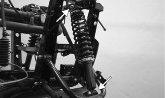
2.Grease the input shaft and front propeller shaft splines. Insert the tension spring (A) into the propeller shaft. Place the differential assembly into position in the frame engaging the front propeller shaft; then install the top mounting cap screw and new lock nut.
Do not tighten at this time. Slide the propeller shaft boot with the two spring clamps over the input shaft coupling.
PK229A
3.Install the two cap screws securing the differential bracket to the bottom of the frame and tighten to secure. Tighten both upper and lower through bolt lock nuts to 29 ft-lb (39.4 N-m).
PK230A
PK231
4.Pour 250 mL (8.45 fl oz) of SAE 80W-90 hypoid lubricant into the differential and install the fill plug.
Tighten to 16 ft-lb (21.8 N-m). Install the differential bladder with hose and secure with the clamps. 5.Install the front axles.
PK233
6.Install the knuckle assemblies onto the axles and ball joints; then secure with four cap screws taking care not to damage the threads when installing. Tighten to 34 ft-lb (46.2 N-m).

PR201
PK234A
7.Connect the front drive actuator connector to the main harness; then secure the wires to the frame with nylon ties. Install the center floorboard kick panel. 8.Apply a light coat of multi-purpose grease to the hub splines; then install the hubs (see Hub in this section). 9.Install the wheels and, using a crisscross pattern, tighten the wheel nuts in 20 ft-lb (27.2 N-m) increments to a final torque of 45 ft-lb (61.2 N-m) (steel wheel), 60 ft-lb (81.6 N-m) (aluminum wheel w/ black nuts), or 80 ft-lb (108.8 N-m) (aluminum wheel w/chrome nuts). 10.Install the front belly panel.
REMOVING REAR DRIVE AXLE 1.Lift the vehicle using a suitable lift to elevate the wheels off the ground. Remove the hubs (see Hub in this section). 2.Remove the cap screw and lock nut securing the knuckle to the upper A-arm. Discard the lock nut.

PK284
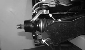
3.Use a tie-down to hold the upper A-arm up and out of the way. While holding the drive axle stationary, pull the top of the knuckle out and down until it is free of the drive axle. Account for the two dust seals (A).
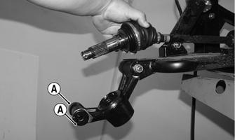
PK314A
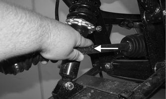
4.Place a drain pan under the vehicle to contain any oil leakage; then pushing the axle shaft in, using a quick outward pulling action, pull the axle assembly from the gear case.
REMOVING FRONT DRIVE AXLE NOTE: For removing a front drive axle, see Front Differential in this section.
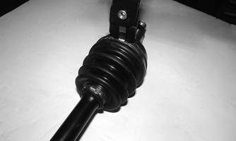
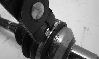
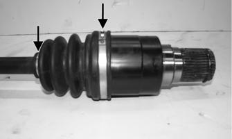
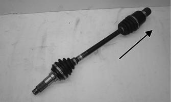
CLEANING AND INSPECTING AXLES NOTE: Always clean and inspect the drive axle components to determine if any service or replacement is necessary. 1.Using a clean towel, wipe away any oil or grease from the axle components. 2.Inspect boots for any tears, cracks, or deterioration. NOTE: If a boot is damaged in any way, it must be replaced with a boot kit. DISASSEMBLING AXLES NOTE: Only the boots are serviceable on the axles; if any other component is worn or damaged, the axle must be replaced. Outboard CV Joint 1.Using CV Boot Clamp Tool, remove and retain both clamps from the outboard CV joint for assembly purposes. Slide the boot back.
CF337
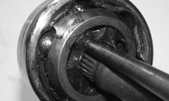
2.Using soft jaws, secure the half-shaft into a vise.
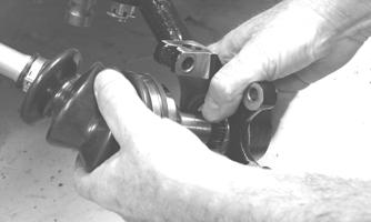
Using a hammer and punch, strike the inner race in multiple positions to remove the joint from the shaft.
PK235
3.Remove the outer CV joint; then remove the boot.

PK236
ASSEMBLING AXLES Outboard CV Joint 1.Install the outer boot with the small clamp onto the axle, making sure the ends of the clamp are positioned correctly. NOTE: The boot is positioned correctly when the small end of the boot seats down into the recessed groove. 2.Using the Boot Clamp Tool, secure the small clamp of the inner boot.
ATV-1048
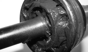
3.Apply 40 grams (1/3 of contents) of grease from the pack into the bearing housing. 4.Verify the circlip is in position within the recess located at the end of the half-shaft. Engage the splines of the CV joint to the splines of the halfshaft. 5.Slide the CV joint toward the circlip, applying slight inward pressure to the CV joint toward the circlip.
Using a punch or flat blade screw driver, compress the circlip into its recess. With pressure still applied to the CV joint, use a plastic dead blow hammer and strike the end of the CV joint to fully seat it to the axle.
PK237
6.Using the Boot Clamp Tool, install and secure the large outside diameter clamp.
PK238
Removing Inboard CV Joint 1.Using the Boot Clamp Tool, remove both clamps from the inboard CV joint. Slide the boot away from the joint.
PK239A
2.Using a pick or small flat blade screw driver, remove the circlip stop ring (A) from the CV housing.
Remove the housing.
PK240A
PK241
3.Note the orientation of the CV joint to the half-shaft.
Remove the snap ring securing the joint to the shaft.
Remove the CV joint; then remove the boot.

PK242A
Installing Inboard CV Joint 1.Place the small diameter clamp and new boot onto the axle. 2.Install the CV joint onto the axle with the large tapered side located toward the end of the axle. Position a new snap ring so the sharp edged side faces toward the end of the axle.
NOTE: In the inboard boot, use the final 80 grams (2/3 of contents) of grease from the pack in the bearing housing.
PK242A
3.Slide the CV housing onto the CV joint; then install a new circlip stop ring (A). Slide the new boot into position; then using the boot clamp tool, secure the two clamps.
PK240A
PK239A
NOTE: Find the half-way point of the inboard CV joint stroke; then secure the clamps. As this is the plunging CV joint. INSTALLING REAR DRIVE AXLE 1.Lightly coat the splines on each side of the axle using anti-seize. Verify the circlip is installed on the inboard CV joint splines. Grasp the inboard CV joint and axle and align the splines of the CV into the ring gear housing; then slide the drive axle into place in the gear case.
PK243A
NOTE: To ensure proper axle seating, give it a light pull; the axle should remain “clipped” in place. 2.Swing the knuckle up and onto the drive axle; then place the knuckle into place in the upper A-arm. Verify both dust seals are installed to each side of the knuckle. Secure the knuckle to the A-arm with a cap screw and a new lock nut. Tighten to 35 ft-lb (47.6
N-m). 3.Install the hubs (see Hub in this section). 4.Install the wheels and using a crisscross pattern, tighten the wheel nuts in 20 ft-lb (27.2 N-m) increments to a final torque of 45 ft-lb (61.2 N-m) (steel wheel), 60 ft-lb (81.6 N-m) (aluminum wheel w/ black nuts), or 80 ft-lb (108.8 N-m) (aluminum wheel w/chrome nuts). 5.Remove the vehicle from the lift. Check the rear gear case lubricant level and add lubricant as necessary.
PK028A
INSTALLING FRONT DRIVE AXLE 1.Lightly coat the splines on each side of the axle with anti-seize. Verify the circlip is installed on the inboard side CV joint splines. Grasp the inboard CV joint and axle and align the splines of the CV into the ring gear housing; then position the drive axle in the gear case and steering knuckle. Insert the ball joints into the steering knuckles. Secure with cap screws tightened to 34 ft-lb (46.2 N-m). 2.Install the hubs (see Hub in this section).
3.Install the wheels and using a crisscross pattern, tighten the wheel nuts in 20 ft-lb (27.2 N-m) increments to a final torque of 45 ft-lb (61.2 N-m) (steel wheel), 60 ft-lb (81.6 N-m) (aluminum wheel w/ black nuts), or 80 ft-lb (108.8 N-m) (aluminum wheel w/chrome nuts). 4.Remove the vehicle from the lift. 5.Check the front differential lubricant level and add lubricant as necessary.

PK027A
Rear Gear Case
REMOVING 1.Drain the lubricant from the rear gear case; then remove both rear drive axles (see Drive Axles). 2.Remove the two patch lock cap screws securing the rear caliper to the gear case. Discard the cap screws.

PK266A
3.Remove the bladder hose from the top of the fitting on the gear case; then remove the two lock nuts and through bolts securing the gear case to the frame.
PK265
4.Pull the rear propeller shaft boots away from the input shaft and rear engine flange. Holding the propeller shaft in place, disengage the gear case from the propeller shaft moving it toward the rear.
Account for the tension spring in the input shaft and boot spring clamps.
PK264
5.Tilt the gear case on its right side; then move it forward through the frame. Remove the gear case from the right side of the frame.

PK267
AT THIS POINT
For servicing the input shaft, pinion gear, needle bearing, ring gear, and axle seals, see Front Differential in this section.
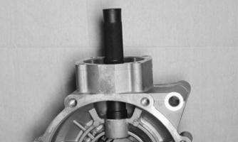
DISASSEMBLING 1.Remove the input shaft spring (A); then remove the cap screw and washer securing the input shaft to the pinion gear shaft. Remove the input shaft assembly.
PK244
PK245A
2.Remove the four cap screws securing the rear caliper mount to the gear case. Record the locations of the two different-length cap screws, which require patch-lock (A). Account for four crush washers.
PK246A
3.Remove the bracket from the gear case. Account for the two dowel pins.

PK247
4.Place the gear case on its side; then remove the cap screws securing the housing cover to the housing. If necessary, use the pry point to aid in removal of the cover. Account for the cover side shim.

PK248
5.Remove the ring gear from the housing. Account for the housing side shim.

PK249
6.Remove the pinion shaft seal; then, using the Pinion
Gear Lock Collar Socket, remove the lock collar.
PK251
PK250
CAUTION
Protective equipment should be worn, as severe injury or burns could result.
7.Using a propane torch, heat the gear case to approximately 200° F (93° C). Carefully using the Pinion
Gear/Shaft Removal tool, remove the pinion gear.
PK252
8.Remove the snap ring securing the needle bearing to the gear case; then, using a suitable bearing puller, remove the bearing.

PK253 PK254
9.Place the pinion gear assembly into a bearing puller; then using a press, separate the bearing from the pinion. Account for the shim, as it is required to be reused upon assembly.
PK255
PK256
10.To replace the cover bearing, use a suitable seal puller to remove the seal; then drive the bearing out from the outside of the cover. 11.To replace the case side bearing, use a suitable seal puller to remove the seal; then remove the snap ring securing the case side bearing.

PK257
12.Using a bearing driver, remove the case side bearing from the inside of the case.
PK258
CLEANING AND INSPECTING 1.Wash all parts in parts cleaning solvent and dry with compressed air.
! WARNING
Always wear safety glasses when working with compressed air.
2.Clean all gasket material and sealant from mating surfaces. 3.Inspect bearings, shafts, and housing for excessive wear, cracks, or discoloration. ASSEMBLING 1.Using a bearing driver adapter the same size as the outer race of the case side bearing, drive the bearing into place, then secure with a new snap ring. Lightly grease a new seal; then install. 2.From the inside of the gear case cover, use a bearing driver adapter the same size as the outside race of the bearing and install. Lightly grease a new seal and install.

PK259
3.Place the pinion gear shim into position; then, using a set of press blocks, press the pinion gear into a new bearing.
PK256
PK260
4.Drive a new pinion gear needle bearing into the case using a bearing driver the same size as the outer race of the bearing; then secure the bearing with the snap ring.
PK261
5.Using soft jaws, secure the gear case into a vise.
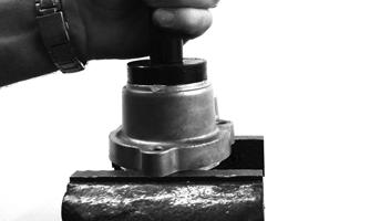
Using a propane torch, heat the gear case to approximately 200° F (93° C); then carefully install the pinion gear assembly into the case. Install the lock collar to secure the pinion into the case. Using the
Pinion Gear Lock Collar Socket, tighten to 125 ft-lb (169.5 N-m).
PK252
PK251
6.Allow the gear case to cool; then lightly grease and install a new pinion shaft seal. If Backlash and Gear
Tooth Contact are within specification, proceed to step 7.
PK247
Checking Backlash A.Place the original case side shim (A) onto the ring gear housing; then place the ring gear into the gear case. Place the cover side shim (B) onto the ring gear housing; then temporarily install and secure the cover to the gear case.
PK262A
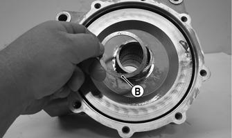
PK249A
B.While holding the pinion gear shaft, place a horizontal type dial gauge through the filler hole and against the ring gear. Rotate the pinion gear shaft back and forth; then record the reading from the dial gauge.
Check at three different locations spaced around the ring gear. Standard specification is 0.05-0.25 mm (0.002-0.010 in.). C.If the measurement is out of adjustment, the shims must be replaced. Refer to the included chart for instructions regarding replacement of the case side (right side) shims. If the case side shims are replaced, the cover side shims must also be replaced to compensate for the backlash adjustment.
Backlash Right Shim Adjustment
Under 0.05 mm (0.0020 in.) Increase shim thickness
Over 0.25 mm (0.010 in.) Decrease shim thickness Gear Tooth Contact A.After backlash has been set, the gear tooth contact must be confirmed. B.Remove the ring gear housing. Thoroughly clean the gear teeth of the ring and pinion gears. Apply machinist’s dye to several teeth of the pinion gear.
Temporarily install the ring gear housing with shims used when setting backlash. Install the cover. C.Rotate the pinion gear shaft back and forth, so the dye-coated gear teeth contact each other. D.The dye should show that the contact area of the two sets of teeth are centered. If contact is too high or too low on the teeth, the pinion gear shaft shim must be exchanged to achieve proper tooth contact while maintaining correct backlash. 7.Place the correctly sized case side shim onto the ring gear; then install into the gear case. Place the cover side shim onto the ring gear.
PK262
PK249
8.Thoroughly clean the matting surface of the case and cover. Apply a suitable sealant to the surface; then install the cover. Using a criss-cross pattern, tighten the cap screws to 16.5 ft-lb (22.4 N-m). 9.Place the two dowel pins into position; then install the brake caliper mount. Using two new patch-lock caps screws, tighten all four cap screws with crush washers to 19 ft-lb (25.8 N-m).
PK246
10.Secure the input shaft to the pinion gear shaft using the cap screw and washer. Tighten to 32 ft-lb (43.5
N-m).
PK245A
INSTALLING 1.Place the spring into the input shaft; then position the gear case into position below the frame mounts.
PK244
2.Lightly grease both splined ends of the rear propeller shaft engaging the splines to the rear engine flange.
Slide the differential forward to engage the splines of the rear propeller shaft.
PK264
3.Lift the differential up into the frame mounts; then insert the through bolts. Using new lock nuts, tighten to 39 ft-lb (53 N-m). Place the bladder hose onto the ventilation fitting located on the top left of the gear case.
PK265
4.Using new patch lock cap screws, install and secure the rear brake caliper to the mount and tighten the screws to 19 ft-lb (25.8 N-m). Install the drive axles (see Drive Axles).
PK266A
5.Remove the fill and check plugs; then add the recommended amount of gear lubricant. Secure the fill and check plugs.
Hub
REMOVING 1.Secure the vehicle on a support stand to elevate the wheel; then remove the wheel(s). NOTE: The jack stands should be placed under the main frame to avoid contact with front suspension components. NOTE: Removing or tightening of the hub nuts requires the axles be locked. To lock the rear axle, place the transmission in park. To lock the front axle, turn the ignition switch to ON and select LOCK on the drive select switch; then place the transmission in park and turn the ignition switch to OFF. ! WARNING
Make sure the vehicle is solidly supported on the support stand to avoid injury.
2.Remove the cotter pin from the axle. Discard the cotter pins.

PK130
3.Remove the hub nut securing the hub. Continue to step 4 to remove the front hubs. 4.Remove the brake caliper(s) on the front only. NOTE: It is not necessary to remove the brake hoses from the calipers for this procedure.
PK106B
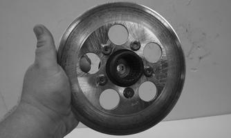
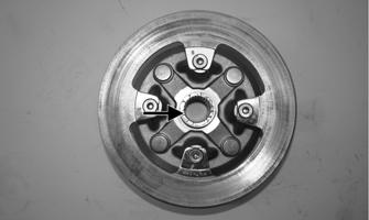
5.Remove the hub assembly. 6.Remove the four cap screws (front) or five cap screws (rear) securing the brake disc to the hub (front) or input shaft (rear). Discard the bolts. NOTE: To replace the rear brake disc, the rear gear case must be removed (see Rear Gear Case).
PK268
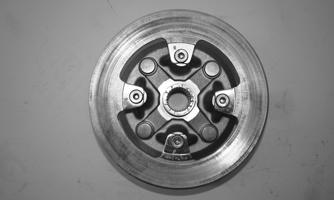
Rear
PK269
CLEANING AND INSPECTING 1.Clean all hub components. 2.Inspect all threads for stripping or damage. 3.Inspect the brake disc (if applicable) for cracks or warping. 4.Inspect the hub for pits, cracks, loose studs, or spline wear. REPLACING WHEEL STUDS 1.Secure the hub in a suitable holding fixture and remove the brake disc (if applicable). 2.Drive the damaged stud out of the hub; then place the new stud into the hub and thread on an appropriate flange nut.

PR250
3.Using a socket and ratchet handle, tighten the nut until the stud is fully drawn into the hub.
PR252A
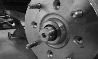
INSTALLING 1.Secure the brake disc to the hub (front) with the four cap screws or to the rear input shaft with five cap screws coated with red Loctite #271. Tighten to 25 ft-lb (34 N-m). 2.Apply grease to the splines of the front hub. If installing the rear brake disc, at this point reinstall the rear gear case (see INSTALLING).
PK268A
NOTE: The remaining instructions are for final installation of the front hubs.
3.Install the hub assembly onto the axle; then place the transmission in park.
PK128
4.Secure the hub assembly with the nut. Tighten to 200 ft-lb (271.2 N-m); then secure with a new cotter pin. NOTE: If the cotter pin cannot be inserted due to misalignment of the hole in the axle and the slots in the nut, tighten the nut until properly aligned.
PK130
5.Secure the brake calipers to the knuckle with two new “patch-lock” cap screws tightened to 19 ft-lb (25.8 N-m).
PK106B
6.Install the wheels and using a crisscross pattern, tighten the wheel nuts in 20 ft-lb (27.2 N-m) increments to a final torque of 45 ft-lb (61.2 N-m) (steel wheel), 60 ft-lb (81.6 N-m) (aluminum wheel w/ black nuts), or 80 ft-lb (108.8 N-m) (aluminum wheel w/chrome nuts). 7.Remove the vehicle from the support stand.
Hydraulic Brake Caliper
! WARNING
The manufacturer recommends only authorized ROV dealers perform hydraulic brake service. Failure to properly repair brake systems can result in loss of control causing severe injury or death.
REMOVING/DISASSEMBLING 1.Secure the vehicle on a support stand to elevate the wheel; then remove the wheel.
! WARNING
Make sure the vehicle is solidly supported on the support stand to avoid injury.
! WARNING
Never let brake fluid contact the eyes. Damage to the eyes will occur. Always wear appropriate protective safety goggles and latex gloves when handling brake fluid.
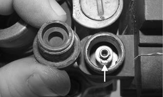
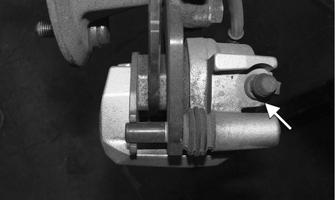
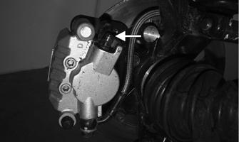
2.Remove the rubber plug covering the bleed screw; then attach a drain hose to the bleed screw. Loosen the bleed screw; then drain the brake fluid from the caliper, hose, and master cylinder through the bleed screw by pumping the brake pedal.
PK004B
CAUTION
Brake fluid is highly corrosive. Do not spill brake fluid on any surface of the vehicle and do not reuse brake fluid.
NOTE: Whenever brake components are removed, disassembled, or repaired where brake fluid is exposed to air, drain all fluid and replace with new DOT 4 brake fluid from an unopened container. Brake fluid readily absorbs moisture from the air significantly lowering the boiling point. This increases the chance of vapor lock reducing braking power and increasing stopping distance. 3.Remove the brake hose (discard the crush washers) from the caliper and close the bleed screw; then remove the caliper. 4.Remove the brake pad pins.
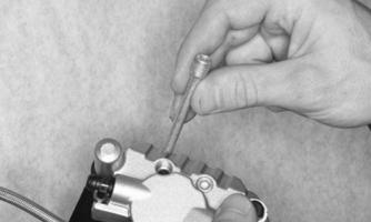
PK270
5.Compress the caliper holder against the caliper and remove the outer brake pad; then remove the inner brake pad. NOTE: If brake pads are to be returned to service, do not allow brake fluid to contaminate them.
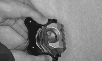
PK271
PK272
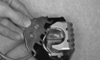
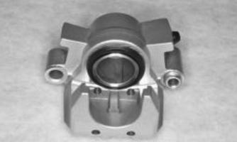
6.Remove the caliper holder from the caliper.
PK273
7.Cover the piston end of the housing with a shop towel; then keeping fingers clear of piston travel.
Apply compressed air to the fluid port to blow the piston free of the housing. Account for the dust and piston seals.
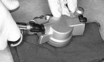
PK274 PK275

! WARNING
Make sure to hold the towel firmly in place or the piston could be ejected from the housing causing injury.
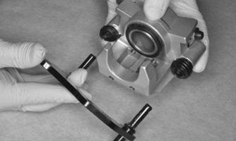
8.Using an appropriate seal removal tool, carefully remove the seals from the brake caliper housing.
Discard all seals, O-rings, and crush washers. CLEANING AND INSPECTING 1.Clean all caliper components (except the brake pads) with DOT 4 brake fluid. Do not wipe dry. 2.Inspect the brake pads for damage and excessive wear.
NOTE: For measuring brake pads, see Periodic Maintenance/Tune-Up - Hydraulic Brake System. 3.Inspect the brake caliper housings for scoring in the piston bores, chipped seal ring grooves, or signs of corrosion or discoloration. 4.Inspect the piston surface for scoring, discoloration, or evidence of binding or galling. 5.Inspect the caliper holder for wear or bending. ASSEMBLING/INSTALLING 1.Install the new piston seal (A) into the brake caliper housing and apply a liberal amount of DOT 4 brake fluid to the cylinder bore of the housing, seals, and brake piston. Place the new dust seal onto the piston (B).
CAUTION
Make sure the seals are properly in place and did not twist or roll during installation.
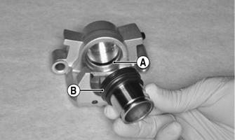
2.Press the piston into the caliper housing using hand pressure only. Completely seat the piston and dust seal; then wipe off any excessive brake fluid.
PK277
3.Apply high-temperature silicone grease to the inside of the caliper holder bores, O-rings, and boots. 4.Install the caliper onto the caliper holder making sure the caliper and holder are correctly oriented. NOTE: It is very important to apply silicone grease to the O-rings, boots, and caliper bores prior to assembly.

PK273A
5.Making sure brake fluid does not contact the brake pads, compress the caliper holder toward the caliper and install the inner brake pad; then install the outer pad.
CAUTION
If brake pads become contaminated with brake fluid, they must be thoroughly cleaned with brake cleaning solvent or replaced with new pads. Failure to do so will result in reduced braking and premature brake pad failure.
6.Secure the brake pads to the caliper with the brake pad pins. Apply blue Loctite to the threads of the pins; then tighten to 13 ft-lb (17.7 N-m).
PK270
7.Place the brake caliper assembly into position and secure with new “patch-lock” cap screws. Tighten the caliper to 25 ft-lb (34 N-m). 8.Place a new crush washer on each side of the brake hose fitting and install it on the caliper. Tighten to 25 ft-lb (34 N-m). 9.Fill the reservoir; then bleed the brake system (see
Periodic Maintenance/Tune-Up - Hydraulic Brake
System).
10.Install the wheels and using a crisscross pattern, tighten the wheel nuts in 20 ft-lb (27.2 N-m) increments to a final torque of 45 ft-lb (61.2 N-m) (steel wheel), 60 ft-lb (81.6 N-m) (aluminum wheel w/ black nuts), or 80 ft-lb (108.8 N-m) (aluminum wheel w/chrome nuts). 11.Remove the vehicle from the support stand and verify brake operation. MASTER CYLINDER ASSEMBLY NOTE: The master cylinder is only serviceable as an assembly. Removing 1.Slide a piece of flexible tubing over one of the caliper bleeder valves and direct the other end into a container. Remove the reservoir cover; then open the bleeder valve. Allow the brake fluid to drain until the reservoir is empty.
! WARNING
Never use brake fluid from an open container or reuse brake fluid. Moisture-contaminated brake fluid could cause vapor build-up (expansion) during hard braking resulting in greatly increased stopping distance or loss of control leading to injury or death.
PK278A
2.Remove the front left splash panel; then remove the two banjo bolts securing the brake switch and banjofittings to the master cylinder.

PK279A
3.Remove the lock pin (A) from the brake rod pin (B).
Remove the brake rod pin from the yoke; then remove two cap screws securing the master cylinder assembly to the frame.
PK280A
Inspecting 1.Inspect the master cylinder push rod and clevis for wear, bending, or elongation of clevis holes. 2.Inspect the push rod boot for tears or deterioration. 3.Inspect the reservoir for cracks and leakage. 4.Inspect the brake hose for cracks and deterioration and the condition of the banjo-fittings. Installing 1.Secure the master cylinder assembly to the frame with two cap screws. Tighten to 15.6 ft-lb (21.2 N-m). 2.Using new crush washers, secure the banjo-fittings to the master cylinder with new banjo bolts and the existing brake switch. Tighten to 25 ft-lb (34 N-m). 3.Install the brake rod pin and secure with a lock pin. 4.Fill the master cylinder and bleed the brake system (see Hydraulic Brake System in the Periodic Maintenance/Tune-Up section).

CAUTION
Brake fluid is highly corrosive. Do not spill brake fluid on any surface of the vehicle.
Troubleshooting Drive System
Troubleshooting Brake System
Problem: Power not transmitted from engine to wheels Condition Remedy
1. Rear axle shaft serration worn — broken 1.Replace shaft
Problem: Power not transmitted from engine to either front wheel Condition Remedy
1. Secondary drive - driven gear teeth broken 1.Replace gear(s) 2. Propeller shaft serration worn — broken 2.Replace shaft 3. Coupling damaged 3.Replace coupling 4. Coupling joint serration worn — damaged 4.Replace joint 5. Front drive — driven bevel gears broken — damaged 5.Replace gear(s) 6. Front differential gears/pinions broken — damaged 6.Replace gears — pinions 7. Front drive actuator not operating 7.Replace fuse — drive select switch — front drive actuator
Problem: Braking poor Condition Remedy
1. Pad worn 1.Replace pads 2. Brake fluid leaking 2.Repair — replace hydraulic system 3. Master cylinder/brake cylinder seal worn 3.Replace seal(s)
Problem: Brake pedal travel excessive Condition Remedy
1. Brake fluid low 1.Add fluid to proper level 2. Piston seal — cup worn 2.Replace seal — cup
Problem: Brake fluid leaking Condition Remedy
1. Connection fittings loose 1.Tighten fittings 2. Hose cracked 2.Replace hose 3. Piston seal worn 3.Replace seal
Problem: Brake pedal spongy Condition Remedy
1. Air trapped in hydraulic system 1.Bleed hydraulic system 2. Brake fluid low 2.Add brake fluid and bleed hydraulic brake system