11 minute read
Drive System

Drive Chain/Sprockets
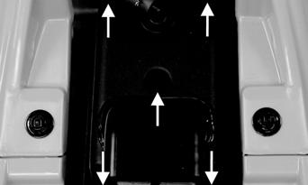
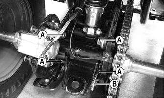
CHECKING DRIVE CHAIN AND SPROCKETS The following drive system components should be inspected periodically to ensure proper operation: A.Chain (excessive stretch or slack). B.Sprockets (excessive wear/hooking, missing or broken teeth). ADJUSTING DRIVE CHAIN 1. Loosen the four cap screws (A) securing the rear axle housing to the rear swing arm.
KM831A
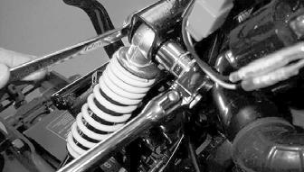
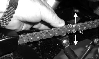
2. Tighten the adjuster nut (B) on the adjusting bolt until approximately 30 mm (1.18 in.) of slack is present at mid-span of the chain.
KM218A
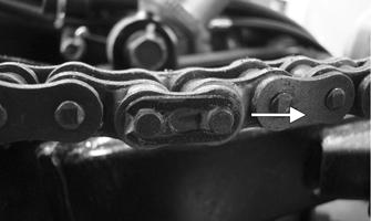
3.Tighten the four cap screws. REMOVING DRIVE CHAIN 1.Remove the drive chain master link clip.
MD2357
2.Remove the link plate and link noting the position of the O-rings; then remove the chain.

KM238A
INSTALLING DRIVE CHAIN 1.Place the drive chain into position on the sprockets. 2.Making sure to place the O-rings into position, install the master link, link plate, and link clip.
KM238A
NOTE: Make sure the closed end of the master link
clip faces the direction of the rotation of the chain.
YT263A
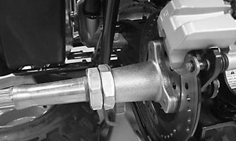
REMOVING FRONT DRIVE SPROCKET 1.With the chain installed and with the rear brake applied, remove the two cap screws securing the spline-lock to the drive sprocket.

YT009A
2.Loosen the drive chain. 3.Remove the drive sprocket and chain; then remove the sprocket from the chain. INSTALLING FRONT DRIVE SPROCKET 1.Place the drive sprocket into the drive chain; then slide onto the driveshaft. 2.Install the spline-lock and two cap screws. 3.Adjust the drive chain. 4.With the rear brake lever lock applied, tighten the cap screws to 8 ft-lb. REMOVING REAR SPROCKET 1.Secure the ATV on a support stand to elevate the rear wheels. Remove the hub nut dust covers.
2.Remove the cotter pins from the axle shaft and discard; then apply the parking brake and remove the castle nuts from the axle. Account for the flat washer.
! WARNING
Make sure the ATV is solidly supported on the support stand to avoid injury.
YT175A
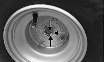
3.Remove the left and right rear wheels. 4.Remove the two axle nuts securing the brake hub to the axle; then remove three cap screws securing the rear sprocket to the sprocket retainer.
YT195A

YT197A
NOTE: It is not necessary to remove the drive chain
in order to remove the rear sprocket.
5.Slide the axle shaft out of the housing from left to right leaving the brake disc and hub and rear sprocket in place. Remove the two cap screws securing the rear chain guard to the axle housing; then lift the rear sprocket out of the chain.

YT198
NOTE: It is not necessary to remove the chain
guard to remove the rear sprocket.
INSTALLING REAR SPROCKET NOTE: Grease all splines with multi-purpose grease
and inspect all O-rings in the brake hub and sprocket retainer. O-rings should be replaced whenever disassembled.
1.Position the sprocket into the chain; then slide the axle with sprocket retainer into the housing from the right side. Install the rear chain guard. 2.Secure the rear sprocket to the sprocket retainer with three cap screws and blue Loctite #242 and tighten to 20 ft-lb.
YT197A
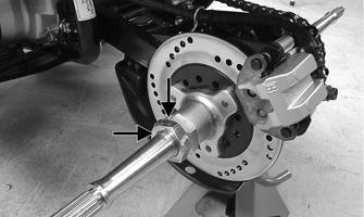
3.Coat the axle threads with red Loctite #271 and install one axle nut; then using an appropriate rear axle nut wrench, tighten the inner axle nut to 86 ft-lb. NOTE: Set the parking brake to prevent the rear axle
from turning.
NOTE: When using a beam-style torque wrench, it
is necessary to calculate the torque value using the following formula due to the offset of the special tool used to tighten the axle nuts. If using a clicker or electronic torque wrench, install the torque wrench at a 90° angle away from the opening of the axle nut wrench.
L x Ts = T L + Ls
T:Torque wrench reading to be calculated Ts:Specified torque value (86 ft-lb) Ls:Tool offset length (center to center) L:Length of torque wrench (handle pivot to headcenter)

ATV2189
4.Install the outer axle nut and tighten to 86 ft-lb. 5.Adjust the chain. 6.Install the rear wheels/hubs and secure with two flat washers and castle nuts. Tighten to 58 ft-lb; then install new cotter pins. NOTE: If cotter pin hole and notch in castle nut do
not align, tighten the nut until the first notch will align with the cotter pin hole.
7.Install the rubber hub nut covers and remove the
ATV from the support stand.
Rear Hub/Drive Axle
REMOVING REAR HUB/DRIVE AXLE 1.Secure the ATV on a support stand to elevate the rear wheels. Remove the hub nut dust covers.
! WARNING
Make sure the ATV is solidly supported on the support stand to avoid injury.
2.Remove the cotter pins from the castle nuts on the rear wheel hubs. 3.Remove the rear wheel hub castle nuts; then slide the rear wheels and hubs off together. Account for the washers. 4.Remove the two axle nuts securing the brake hub to the axle. Remove the chain guard.
YT195A
5.Remove the drive chain. 6.Remove the rear sprocket. 7.Remove the drive axle by sliding it out the right side of the axle housing.
AT THIS POINT
If the technician’s objective is to service/replace the drive axle, the axle housing does not have to be removed from the swing arm. The axle can be pulled out the right side of the axle housing. Axle bearings can also be replaced without removing the axle housing from the swing arm, but the rear axle housing cover and brake hub will need to be removed. The axle housing should only be removed if it needs to be serviced or replaced.
REMOVING BEARINGS AND SEALS 1.Secure the ATV on a support stand to elevate the rear wheels.
! WARNING
Make sure the ATV is solidly supported on the support stand to avoid injury.
2.Remove the wheels and hubs. 3.Using an appropriate prying tool, carefully pry out the seals from each side of the axle housing.
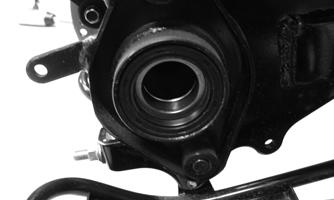
KM232
4.Drive out the bearings from the axle housing.
Account for center axle housing spacer.
REMOVING AXLE HOUSING 1.Secure the ATV on a support stand to elevate the rear wheels.
! WARNING
Make sure the ATV is solidly supported on the support stand to avoid injury.
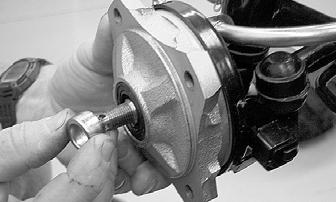
2.Remove two cap screws securing the brake caliper to the axle housing; then lift the caliper off the disc.

YT235A
3.Remove drive chain, wheels, hubs, and axle as necessary. NOTE: Do not remove more components than nec-
essary to perform the intended service. The axle housing will separate from the swing arm with all components attached if necessary.
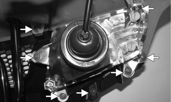
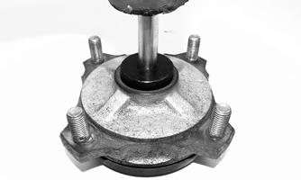
4.Remove the four cap screws (A) securing the axle housing to the swing arm; then remove the axle housing.

KM217B

KM212A
CLEANING AND INSPECTING NOTE: Always clean and inspect the drive axle
components to determine if any service or replacement is necessary. Replace all components showing signs of wear or damage.
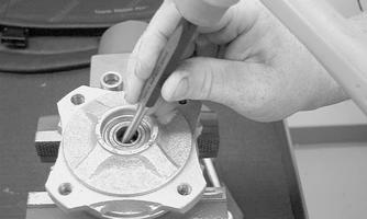
1.Using a clean towel, wipe away any oil or grease. 2.Inspect bearings for smooth operation. 3.Inspect seals for tears, cracks, or deterioration. 4.Inspect splines on axle for damage or wear. 5.Inspect threads on end of axle for damage or stripped threads. 6.Inspect axle for straightness by rolling it on a flat surface and checking for wobble. 7.Inspect axle housing for dents or warpage that might interfere with bearing bore or alignment. INSTALLING BEARINGS AND SEALS 1.Using a plastic mallet and bearing driver or appropriate size socket, carefully install the first bearing into the axle housing.

KM226
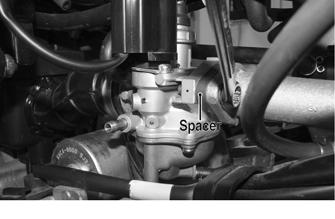
2.Place the center axle housing spacer in the axle housing; then using a plastic mallet, install the second bearing. NOTE: It may be helpful to insert the axle through
the previously installed bearing and into the axle housing to align the center axle housing spacer with the bearing bore. Axle installation may be difficult if the spacer is offset from the bearing bore.
3.Apply a light coat of axle bearing grease to the inside (mating surface) of the seals; then using a plastic mallet, install the seals.
KM223
INSTALLING AXLE HOUSING 1.Position axle housing in swing arm; then install and finger-tighten the four cap screws securing the axle housing to the swing arm. 2.Install the brake caliper to the axle housing.
YT235A
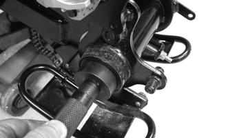
3.Install the drive chain. 4.Adjust the drive chain slack; then tighten the four cap screws (from step 1) to 29 ft-lb. INSTALLING DRIVE AXLE/REAR HUB 1.Slowly slide the axle into the axle housing. NOTE: The axle may have to be turned from side-
to-side slightly during installing to get the axle through the center axle housing spacer.

MD2374
2.Slide the axle through the brake disc.

KM234
3.Secure the rear sprocket to the sprocket retainer. Tighten the three cap screws (threads coated with blue Loctite #242) to 20 ft-lb. Install the chain guard.
YT197A
4.Install the axle nuts securing the brake hub to the axle. 5.Install the drive chain. 6.Install the rear wheel/hub assemblies. Tighten the castle nuts to 58 ft-lb; then install new cotter pins.
Front Hub
REMOVING HUB 1.Secure the ATV on a support stand to elevate the front wheels. Remove the hub nut dust covers; then remove the wheels.
! WARNING
Make sure the ATV is solidly supported on the support stand to avoid injury.
2.Remove the cotter pin from the castle nut. NOTE: During installation, a new cotter pin should
be installed.
3.Remove the castle nut securing the hub. Account for a washer.

MD2133
4.Remove the hub assembly. Account for outer hub spacer. 5.Repeat procedure for other hub. CLEANING AND INSPECTING 1.Clean all hub components. 2.Inspect all threads for stripping or damage. 3.Inspect the brake shoes for excessive wear or gouges. 4.Inspect the sealing area of the hub for pits. 5.Inspect the hub splines for signs of wear. 6.Inspect the hub for cracks. 7.Verify the bearings turn freely. REMOVING HUB BEARINGS AND SEALS 1.Carefully pry out inner and outer seals.

MD2385
2.Drive out the inner and outer bearings. Account for a spacer.
MD2384A
3.Repeat procedure for the other hub. INSTALLING HUB BEARINGS AND SEALS 1.Lightly lubricate the bearings with bearing grease; then using a plastic mallet and a bearing driver or appropriate size socket, install the inner bearing into the hub.

YT231
2.Install the inner hub spacer; then install the outer bearing.
YT232
3.Using a plastic mallet, install the inner and outer seals into the hub.

MD2380
4.Repeat procedure for the other hub. INSTALLING HUB 1.Lightly lubricate the seals with bearing grease; then install the hub assembly. 2.Install the outer spacer, washer, and castle nut.
Tighten the castle nut to 45 ft-lb; then install a new cotter pin. Install the dust cover.
MD2388

MD2354
3.Install wheel. Tighten the four cap screws to 30 ft-lb. 4.Repeat procedure for other hub assembly.
Brake Systems
For information regarding the brake systems, see Periodic Maintenance/Tune-Up section.
Troubleshooting Drive System
Troubleshooting Brake System
Problem: Power not transmitted from engine to wheels Condition Remedy
1. Drive chain worn — broken 1.Replace chain 2. Countershaft sprocket worn — broken 2.Replace countershaft sprocket 3. Rear sprocket worn — broken 3.Replace rear sprocket 4. Chain slipped off sprockets 4.Replace — adjust drive chain 5. Master link worn — broken — missing 5.Replace master link
Problem: Clutch slipping Condition Remedy
1. Clutch shoes worn — damaged 1.Replace clutch shoes
Problem: Clutch dragging Condition Remedy
1. Clutch return springs weak 1.Replace return springs 2. Clutch worn — damaged 2.Replace clutch
Problem: Braking poor Condition Remedy
1. Brake shoe(s) — pad(s) worn 1.Replace brake shoe(s) — pad(s) 2. Lever free-play excessive 2.Adjust free-play 3. Brake drum(s) worn 3.Replace brake drum(s)
Problem: Brakes drag Condition Remedy
1. Lever free-play less than minimum 1.Adjust free-play 2. Brake shoe return spring(s) loose — sprung 2.Connect — replace return spring(s)