11 minute read
Fuel System

This section has been organized for servicing the fuel system. The technician should use discretion and sound judgment when removing/disassembling and assembling/ installing components.
! WARNING
Whenever any maintenance or inspection is made on a fuel system when there may be fuel leakage, there should be no welding, smoking, open flames, etc., in the area.
Pre-Maintenance Checks
Before troubleshooting the fuel system, several simple checks should be performed. Many times what appears to be a serious problem is only a minor one. 1.Make sure the gas tank shut-off valve was in the
OPEN position and check for fuel flow from the tank to the carburetor.
2.Turn the shut-off valve to the CLOSED position; then remove the in-line fuel filter. If the filter is dirty, replace the filter. 3.Install a new filter making sure the arrow on the filter is directed toward the engine. 4.Check the gas tank fuel and vent hoses to ensure that all are correctly connected; then check for cracks. If any cracks are evident in the hoses, replace them making sure none are against any hot or moving parts. Hoses must fit tightly. 5.Check the carburetor float chamber by loosening the drain screw (I) and inspect it for water or debris. If seen, clean by removing the float chamber cap screw and cleaning the float chamber. 6.When ready for operation, turn the shut-off valve to the OPEN position.
Carburetor
REMOVING NOTE: Before removing the carburetor, be sure the
gas tank shut-off valve is in the OFF position.
1.Remove the screws securing the air cleaner cover to the air cleaner case and account for the filter and retaining plate. 2.Remove the flanged nuts securing the air cleaner assembly to the carburetor and engine. 3.Remove the air cleaner case and intake tube from the carburetor and engine. Account for the gasket. 4.Remove the drain screw w/spring (I) from the float chamber and drain any gasoline from the chamber; then install the drain screw w/spring. 5.Remove the fuel supply hose. 6.Disconnect the rod and spring from the carburetor; then loosen the pinch screw and jam nuts securing the choke cable to the carburetor.
7.Slide the carburetor off the mounting studs. Account for a gasket, insulator, and a gasket.
DISASSEMBLING
SNO-997
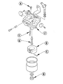
1.Remove the pilot jet (A) from the carburetor.
2.Remove the cap screw (B) securing the float chamber to the carburetor; then remove the chamber and account for the rubber gasket. 3.Remove the float pin (C) securing the float (D) to the carburetor body; then remove the float and needle jet assembly (E). 4.Remove the main jet (F) and the nozzle (G) from the carburetor tower.
DO NOT place any non-metallic components in partscleaning solvent or carburetor cleaner because damage or deterioration will result.
1.Place all metallic components in a wire basket and submerge in carburetor cleaner. 2.Soak for approximately 30 minutes; then rinse with fresh parts-cleaning solvent. 3.Wash all non-metallic components with soap and water. Rinse thoroughly. 4.Dry all components with compressed air only making sure all holes, orifices, and channels are unobstructed.
5.Blow compressed air through all hoses to remove any obstructions. ! WARNING
Always wear safety glasses when drying components with compressed air.
CAUTION
DO NOT use wire or small drill bits to clean carburetor orifices, holes, or channels. Distorted or damaged orifices, holes, or channels can result in poor carburetor operation.
INSPECTING 1.Inspect the mixing body and jet orifices for cracks, nicks, stripped threads, and any other imperfections in the casting. 2.Inspect the float for perforations or damage. 3.Inspect the gaskets for distortion, tears, or noticeable damage. 4.When applicable, inspect the idle fuel adjuster screw, needle jet assembly, and pilot jet for wear, damage, or distortion.
5.Inspect the nozzle and main jet for obstructions or damage. 6.Inspect the carburetor insulator for damage, cracks, and tightness.
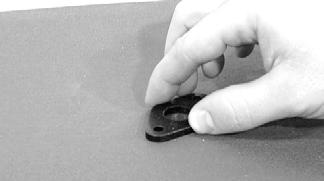
7.Place the carburetor insulator on a surface plate covered with #400 grit wet-or-dry sandpaper. Move the insulator over the surface plate using a figure-eight motion. The motion should produce an even wear pattern over the entire sealing area.
CAUTION
An air leak between the carburetor and engine will cause a lean condition and poor engine performance.
CAUTION
Water or parts-cleaning solvent must be used in conjunction with the wet-or-dry sandpaper or damage to the sealing surfaces may result.
A739
8.Inspect the condition of the throttle return spring.
CHECKING FLOAT HEIGHT 1.Remove the cap screw securing the float chamber; then remove the float chamber from the carburetor and account for the rubber gasket. 2.With the carburetor in an upside-down position, lift the float so the tip of the float lightly contacts the float arm; then measure the float height from the body of the carburetor and under-side of the float.
Measurement should be 0.63".

IO108
CAUTION
Do not bend the float in an attempt to adjust the height. Correct float height is obtained by replacing the needle jet assembly and/or the float.
SNO-997
1.Install the nozzle (G) and main jet (F) into the carburetor tower.
2.Place the needle jet assembly (E) and the float (D) into position and secure to the carburetor body with the float pin (C). 3.Secure the float chamber w/rubber gasket to the carburetor with the cap screw (B). 4.Install the pilot jet (A).
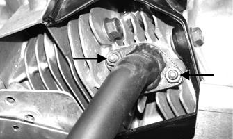
INSTALLING 1.Install the gasket, insulator, and a gasket; then with the governor rod and spring installed on the carburetor, place the carburetor into position on the mounting studs. Install the flanged nuts and tighten to 96 in.-lb.

GF318D
2.Install the choke cable and secure the cable with the jam nuts and pinch screw. 3.Install the fuel supply hose on the carburetor. 4.Place the gasket and air cleaner assembly into position on the carburetor; then secure with the flanged nuts and cap screw. 5.Secure the air cleaner cover to the air cleaner with the screws. Tighten to 96 in.-lb. 6.Turn the gas tank shut-off valve to the OPEN position and check the fuel system for leakage. 7.Adjust the carburetor (see ADJUSTING sub-section).
ADJUSTING The carburetor has been calibrated for average riding conditions; however, altitude, temperature, and general wear may necessitate certain carburetor adjustments. Since carburetor adjustments critically affect engine performance, three external adjustments can be made on the carburetor. These are the throttle stop screw, idle fuel adjuster screw, and throttle cable.
0744-921
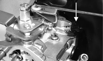
Throttle Stop Screw This screw controls the seating position of the throttle valve which in turn determines the proper idle speed. Rotate the screw clockwise to increase engine idle speed and counterclockwise to decrease engine idle speed.
Idle Fuel Adjuster Screw This screw determines the fuel/air mixture for idling. To adjust, use the following procedure: 1.Start the engine and allow to run at half throttle 5-10 minutes to warm up. 2.Place the throttle in the idle position; then rotate the idle fuel adjuster screw/cap in or out within the adjustment range to obtain smooth low speed performance.
IO110B
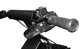
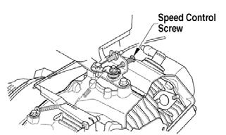
Throttle Cable The correct throttle cable adjustment is when (with the engine OFF) the carburetor throttle is completely open (against its limit) while the throttle lever lightly contacts the handlebar grip. The throttle arm on the carburetor should also contact the speed control screw when the throttle lever is released.
1.To adjust the throttle cable, loosen the throttle cable jam nuts.
! WARNING
Do not attempt to adjust the throttle cable with the engine running. Personal injury could result.

0744-922
2.Pull all slack from the throttle cable wire and exert slight tension on the wire. 3.Tighten the throttle cable jam nuts. ! WARNING
DO NOT operate the snowmobile when any component in the throttle system is damaged, frayed, kinked, worn, or improperly adjusted. If the snowmobile is operated when the throttle system is not functioning properly, personal injury could result.
Speed Control Screw
0744-949
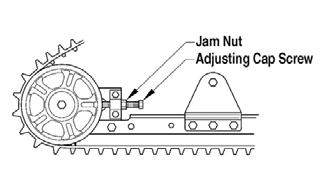
The maximum speed of the snowmobile can be reduced by adjusting the speed control screw. To reduce the maximum speed, rotate the speed control screw clockwise. DO NOT EVER INCREASE THE
MAXIMUM SPEED BEYOND THE ORIGINAL 8
MPH MAXIMUM. ! WARNING

Whenever any maintenance or inspection is made on a fuel system when there may be fuel leakage, there should be no welding, smoking, open flames, etc., in the area.
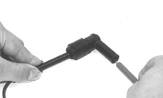
Arctic Cat recommends that the in-line fuel filter be checked once a month. The filter is located in the fuel hose between the gas tank and fuel pump. The only cleaning possible is back-flushing the filter using fresh gasoline. To check, clean, or replace the filter, use the following procedure: 1.Using a suitable hose-clamping pliers, pinch off the fuel hose between the gas tank and the filter. 2.Remove and discard the clamps from the fuel hose at the filter; then slowly remove the fuel hoses from the filter. Properly dispose of the excess fuel from the filter.
3.Install the in-line fuel filter to the fuel hoses so the arrow on the filter points toward the fuel pump.
Make sure the hoses fit tightly on the filter. If a hose does not fit tightly, cut 6 mm (1/4 in.) from the end of the hose; then install on the filter. Install new clamps and remove the clamping pliers.
CAUTION
The fuel hoses must fit tightly on the fuel filter. If the hose length doesn’t permit this procedure, replace the fuel hose. Also, after installing the fuel hoses on the filter, check to be sure that the hoses do not contact any hot or rotating components.
Throttle Cable
REMOVING AND INSPECTING 1.Remove the C-clip securing the lever pin in the throttle lever; then remove the pin and the lever.
ZR-105
2.Disconnect the throttle cable from the lever; then slide the cable out of the lever.

ZR-108
3.Remove the C-clip securing the cable in the throttle control; then remove the cable from the throttle control.

ZR-109
2.Seat the cable drum into the throttle lever recess; then secure the throttle lever to the throttle control with a pin and C-clip.
ZR-109
4.Remove the handlebar pad and cut the cable tie securing the throttle cable to the steering post. NOTE: Note the location of the cable tie for assem-
bly.
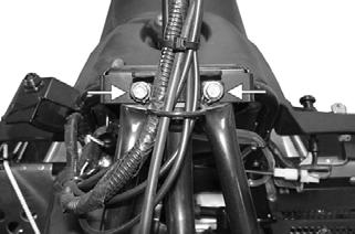
5.Rotate the throttle cable lever of the governor control arm to the wide-open position and route the cable end out of the arm; then loosen the throttle cable jam nuts and remove the throttle cable.
0744-922
6.Inspect the throttle cable for damage or fraying.
INSTALLING 1.Route the cable through the slot in the throttle control and insert the cable into the throttle control.
Secure the cable with a C-clip.
ZR-108
ZR-105
3.Place the throttle cable into the throttle cable bracket and secure with jam nuts. 4.Slide the end of the throttle cable into the throttle cable lever.
5.Secure the throttle cable to the steering post with a cable tie; then install the handlebar pad. 6.Open and close the throttle lever to make sure of no binding or sticking. NOTE: At this point, adjust the throttle cable (see
Throttle Cable in the Carburetor sub-section).
ADJUSTING To adjust the throttle cable, see Carburetor – ADJUSTING sub-section.
Troubleshooting Fuel System
Problem: Carburetor Too Rich (0-1/4 Opening) Condition Remedy
1. Choke valve will not seat 2. Idle fuel adjuster screw out of adjustment 3. Float/needle jet obstructed — damaged — adjusted incorrectly 4. Pilot jet loose 1.Adjust — service — replace choke cable — assembly 2.Adjust idle fuel adjuster screw 3.Remove obstruction — replace needle jet — float
4.Tighten pilot jet
Problem: Carburetor Too Rich (1/4-3/4 Opening) Condition Remedy
1. Pilot jet too large 2. Float/needle jet obstructed — damaged — adjusted incorrectly 3. Main jet loose — too large 4. Primary air passage obstructed 1.Replace pilot jet 2.Remove obstruction — replace needle jet — float
3.Tighten — replace main jet 4.Remove obstruction
Problem: Carburetor Too Rich (3/4-WOT Opening) Condition Remedy
1. Main jet loose — too large 2. Float/needle jet obstructed — damaged — adjusted incorrectly 1.Tighten — replace with smaller main jet 2.Remove obstruction — replace needle jet — float
Problem: Carburetor Too Lean (0-1/4 Opening) Condition Remedy
1. Choke valve hanging open 2. Pilot jet — outlet obstructed 3. Float/needle jet obstructed — damaged — adjusted incorrectly 1.Adjust — service choke cable — valve assembly 2.Remove obstruction 3.Remove obstruction — replace needle jet — float
Problem: Carburetor Too Lean (1/4-3/4 Opening) Condition
Remedy
1. Pilot jet — outlet — main jet obstructed 2. Float/needle jet obstructed — damaged — adjusted incorrectly 1.Remove obstruction 2.Remove obstruction — replace needle jet — float
Problem: Carburetor Too Lean (3/4-WOT Opening) Condition Remedy
1. Main jet obstructed — too small 2. Float/needle jet obstructed — damaged — adjusted incorrectly 1.Remove obstruction — replace with larger main jet 2.Remove obstruction — replace needle jet — float
Problem: General Fuel System (Engine Cuts Out at High RPM) Condition Remedy
1. Fuel delivery inadequate 2. In-line fuel filter obstructed — damaged 3. Gasoline contaminated 4. Gas-tank vent — hose obstructed 1.Repair — replace hose 2.Remove obstruction — replace in-line fuel filter 3.Replace gasoline — de-ice — clean carburetor 4.Remove obstruction — replace vent — hose