64 minute read
Electrical System


TESTING ELECTRICAL COMPONENTS All electrical tests should be made using the CATT II or the Fluke Model 77 Multimeter. The CATT II can return data for certain components which are identified at the beginning of their respective sub-section. If any other type of meter is used, readings may vary due to internal circuitry. When troubleshooting a specific component, always verify first that the fuse(s) are good, that the lights are working properly, that the connections are clean and tight, that the battery is fully charged, and that all appropriate switches are activated. NOTE: For absolute accuracy, all tests should be
made at room temperature of 68° F (20° C).
NOTE: Certain components and sensors can be
checked by using the diagnostic system and digital gauge (see Gauge Diagnostic Menu in this section for more information).
SPECIAL TOOLS A number of special tools must be available to the technician when performing service procedures in this section. Refer to the current Special Tools Catalog for the appropriate tool description. NOTE: When indicated for use, each special tool
will be identified by its specific name, as shown in the chart below, and capitalized.
NOTE: Special tools are available from the Service
Department.
CAT II
Description
Fluke Model 77 Multimeter MaxiClips EFI Pressure Test Kit
p/n
0544-023 0644-559 0744-041 0644-587
Battery
Component data can be retrieved using the CATT II. Utilize the Sensor Data screen.
NOTE: Preliminary checks may be performed on
this component using the diagnostic mode on the LCD gauge (see Gauge Diagnostic Menu in this section).
The battery is located in a compartment between the seats.
NOTE: To access the battery, remove the driver’s
seat; then turn the fastener counterclockwise and remove the battery access cover.
XX124
XX132
After being in service, batteries require regular cleaning and recharging in order to deliver peak performance and maximum service life. The following procedures are recommended for cleaning and maintaining sealed batteries. Always read and follow instructions provided with battery chargers and battery products. NOTE: Refer to all warnings and cautions provided
with the battery or battery maintainer/charger.
Loss of battery charge may be caused by ambient temperature, ignition OFF current draw, corroded terminals, self discharge, frequent start/stops, and short engine run times. Frequent winch usage, snowplowing, extended low RPM operation, short trips, and high amperage accessory usage are also reasons for battery discharge.
MAINTENANCE CHARGING NOTE: The manufacturer recommends the use of
the CTEK Multi US 800 or the CTEK Multi US 3300 for battery maintenance charging. Maintenance charging is required on all batteries not used for more than two weeks or as required by battery drain.

1.When charging a battery in the vehicle, be sure the ignition switch is in the OFF position. 2.Clean the battery terminals with a solution of baking soda and water.
NOTE: The sealing strip should NOT be removed
and NO fluid should be added.
3.Be sure the charger and battery are in a well-ventilated area. Be sure the charger is unplugged from the 110-volt electrical outlet.
4.Connect the red terminal lead from the charger to the positive terminal of the battery; then connect the black terminal lead of the charger to the negative terminal of the battery. NOTE: Optional battery charging adapters are
available from your authorized dealer to connect directly to your vehicle from the recommended chargers to simplify the maintenance charging process. Check with your authorized dealer for proper installation of these charging adapter connectors.
5.Plug the battery charger into a 110-volt electrical outlet.
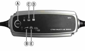
6.If using the CTEK Multi US 800, there are no further buttons to push. If using the CTEK Multi US 3300, press the Mode button (A) at the left of the charger until the Maintenance Charge Icon (B) at the bottom illuminates. The Normal Charge Indicator (C) should illuminate on the upper portion of the battery charger. NOTE: The maintainer/charger will charge the bat-
tery to 95% capacity at which time the Maintenance Charge Indicator (D) will illuminate and the maintainer/charger will change to pulse/float maintenance. If the battery falls below 12.9 DC volts, the charger will automatically start again at the first step of the charge sequence.
3300C
NOTE: Not using a battery charger with the proper
float maintenance will damage the battery if connected over extended periods.
CHARGING NOTE: The manufacturer recommends the use of
the CTEK Multi US 800 or the CTEK Multi US 3300 for battery maintenance charging.
1.Be sure the battery and terminals have been cleaned with a baking soda and water solution. 2.Be sure the charger and battery are in a well-ventilated area. Be sure the charger is unplugged from the 110-volt electrical outlet.
3.Connect the red terminal lead from the charger to the positive terminal of the battery; then connect the black terminal lead of the charger to the negative terminal of the battery. 4.Plug the charger into a 110-volt electrical outlet. 5.By pushing the Mode button (A) on the left side of the charger, select the Normal Charge Icon (E). The
Normal Charge Indicator (C) should illuminate on the upper left portion of the charger. 6.The battery will charge to 95% of its capacity at which time the Maintenance Charge Indicator (D) will illuminate.
NOTE: For optimal charge and performance, leave
the charger connected to the battery for a minimum 1 hour after the Maintenance Charge Indicator (D) illuminates. If the battery becomes hot to the touch, stop charging. Resume after it has cooled.
7.Once the battery has reached full charge, unplug the charger from the 110-volt electrical outlet.
Electronic Power Steering (EPS)
Component data can be retrieved using the CATT II. Utilize the Sensor Data screen.
The EPS system is an electro-mechanical device that utilizes 12-volt DC power to drive a motor linked to the steering shaft to assist the driver when rotating the steering wheel. Driver steering inputs are detected by a torque-sensing transducer assembly within the EPS housing. These inputs are converted to electronic signals by the transducer and control circuitry to tell the motor which way to drive the steering shaft. When no steering input (pressure on the steering wheel) is detected, no torque signal is generated, and no steering assist is provided by the motor. If an electrical-related EPS system malfunction occurs, a diagnostic trouble code (DTC) will be displayed on the LCD gauge. Check for updates and verify any active DTCs using the most up-to-date CATT II software. The following is a list of DTCs, possible conditions, and causes.
NOTE: If no active codes are present on the LCD or
verified through the CATT II and the vehicle is experiencing steering-related issues, there may be a mechanical steering-related issue. In this case, the EPS is not the cause of the issue. Components that may contribute to this type of issue could be abnormal tire wear, bad wheel bearings, ball joints, tie rod ends, tie rods, or bushings. Check the complete steering system for any sign of wear or misalignment.
NOTE: If any codes are active and verified with the
CATT II, EPS replacement is not always necessary. Follow the instructions listed in the chart to potentially correct the malfunction.
Code Fault Description Fault Condition
C1301 Over Current EPS internal over-current condition has been detected. C1302 Excessive Current Error EPS internal current measurement error has been detected.
C1303 Torque Sensor Range Fault C1304 Torque Sensor Linearity Fault
EPS internal torque sensor range condition has been detected. EPS internal torque sensor linearity condition has been detected. C1305 Rotor Position Encoder EPS internal rotor position encoder condition has been detected.
Possible Cause
Internal EPS condition
Internal EPS condition
Internal EPS condition
Internal EPS condition
Internal EPS condition
EPS Fault Recovery Method
Correct EPS condition*
Correct EPS condition*
Correct EPS condition*
Correct EPS condition*
Correct EPS condition*
C1306 System Voltage Low EPS battery power low-voltage condition has been detected. System voltage low (less than 11 VDC at the EPS). Wire harness issue, faulty voltage regulator, weak battery or loose battery terminals. EPS will auto-recover when the battery supply returns to normal.
C1307 System Voltage High EPS battery power over-voltage condition has been detected. System voltage high (more than 16 VDC at the EPS). Wire harness issue, faulty voltage regulator or loose battery terminals. EPS will auto-recover when the battery supply returns to normal.
C1308 Temperature above 110° C (230° F) EPS internal 110° C (230° F) over-temp condition has been detected. Clean the EPS housing and cooling fins. EPS will auto-recover when internal temperature drops below 105° C (221° F).
C1309 Temperature above 120° C (248° F) EPS internal 120° C (248° F) over-temp condition has been detected. Clean the EPS housing and cooling fins. EPS will auto-recover when internal temperature drops below 115° C (239° F).
C1310 Vehicle Speed High Vehicle speed signal received by the EPS exceeds the maximum speed specification. Intermittent main harness wires, defective speed-sensor, or intermittent speed sensor wires. EPS will auto-recover when the vehicle speed signal drops below the maximum speed specification.
C1311 Vehicle Speed Low Vehicle speed signal received by the EPS is zero or missing. Broken main harness wires, defective speed sensor, or broken speed sensor wires.
C1312 Vehicle Speed Faulty Vehicle speed CAN signal received by the EPS incorrect or missing. Broken main harness CAN wires, defective speed-sensor, or broken speed sensor wires. EPS will auto-recover when the vehicle speed signal returns to normal. EPS will auto-recover when the vehicle speed signal returns to normal.
C1313 Engine RPM High Engine RPM signal received by the EPS exceeds the maximum RPM specification. Intermittent main harness RPM wires, intermittent voltage regulator, intermittent ACG stator wires. EPS will auto-recover when engine RPM signal drops below the maximum RPM specification.
C1314 Engine RPM Low Engine RPM signal received by the EPS suddenly dropped below 500 RPM.
C1315 Engine RPM Faulty Engine RPM CAN signal received by the EPS incorrect or missing. C1316 EEPROM Error EPS internal memory error has been detected. Handlebar switch in the “OFF” position, broken main harness RPM wires, defect voltage regulator, broken ACG stator wires. Broken main harness CAN wires or defective ECM. Internal EPS condition EPS will auto-recover when engine RPM signal returns to normal.
EPS will auto-recover when engine RPM signal returns to normal. Correct EPS condition*
C1317 CAN Bus Error The EPS has lost CAN communication with the EFI ECM. Broken CAN wires in the main harness. EFI ECM connector has been disconnected. Correct EPS condition*
C1318 Internal CRC Error EPS internal CRC calculation condition has been detected.
C1319 Boot Counter Exceeded EPS internal application code condition has been detected. EPS reflash has failed. Battery power was lost, or the key switch was turned off, during EPS reflash programming EPS must be reprogrammed
Intermittent power has prevented a successful application code launch. Correct EPS power condition*
C1320 Incorrect Vehicle Speed-to-RPM Ratio Vehicle speed signal received by the EPS exceeds 10 mph, but the engine RPM signal less than 500 RPM. Intermittent or broken main harness RPM wires, intermittent voltage regulator, intermittent or broken ACG stator wires.
C1321 Vehicle Speed Erratic Vehicle speed signal received by the EPS changing at an unrealistic rate. Intermittent main harness, intermittent speed sensor, dirty speed senor or trigger wheel. Correct EPS condition*
Correct EPS vehicle speed signal condition*
C1322 Engine RPM Lost Engine RPM signal received by the EPS exceeds 500 RPM and then is zero or missing
C1323 “EPS OFF” Gauge Display Battery power has been applied to the EPS for more than 5 minutes, but no engine RPM signal has been detected. Handlebar switch in the “OFF” position, broken main harness RPM wires, defect voltage regulator, broken ACG stator wires EPS will auto-recover when engine RPM signal returns to normal.
The EPS has been automatically disabled, after 5 minutes of inactivity, to conserve battery power. EPS will auto-recover when engine is started or the key switch is cycled On-Off-On.
C1324 Loss of CAN Communication with EPS Unit The gauge has lost CAN communication with the EPS.
C1325 Dual Loss EPS loss of both the vehicle speed and the engine RPM signals has been detected. Broken CAN wires in the main harness or disconnected EPS. This is not an EPS generated DTC; gauge DTC display only. Gauge DTC display will clear when the EPS-to-gauge CAN communication is restored.
Handlebar switch in the “OFF” position, the engine stalled (key switch “ON”), broken harness wires, loss of CAN data signal. EPS will auto-recover when either the vehicle speed or engine RPM signal is restored.
C1326 Rotor Position Encoder EPS internal rotor position encoder variance condition has been detected. Internal EPS condition Correct EPS condition*
C1327 Voltage Converter Error (Low) C1328 Voltage Converter Error (High) EPS internal voltage converter low-voltage condition has been detected. Internal EPS condition
EPS internal voltage converter over-voltage condition has been detected. Internal EPS condition
C1329 Internal Data Error EPS internal preloaded data condition has been detected. Internal EPS condition Correct EPS condition*
Correct EPS condition*
EPS must be reprogrammed
NOTE: The EPS assembly is not serviceable and
must not be disassembled or EPS warranty will be voided.
1.Check 30-amp EPS fuse. 2.With the ignition off, disconnect the two-wire EPS power connector on the EPS assembly and connect a volt meter set to DC voltage to the harness (black meter lead to BLK and red meter lead to
ORG/BRN).With the ignition switch in the ON position, the meter should read battery voltage (if correct voltage is not present, check connections and wiring harness).
3.With ignition switch off, disconnect the three-wire connector on the EPS assembly and connect a volt meter set to DC voltage to the harness (red meter lead to the ORG wire and black meter lead to battery ground.) With the ignition switch in the on position, the meter should read battery voltage (if correct voltage is not present, check for loose fittings or connections in the wiring harness).
CAUTION
Do not attempt to check resistance of the EPS motor. There are internal capacitors holding a charge that can cause internal damage to an ohmmeter.
CAUTION
If the CATT II has confirmed an active DTC relating to the CAN communication wires, use extreme caution when testing the wires. Do not probe the ECM connector with meter leads; instead use a small T-pin or other suitable testing component to make light and proper contact.
CAUTION
Never disconnect the ECM connector with the battery cables installed onto the battery.
NOTE: If after completing the preceding tests and
possible solutions with normal results an EPS issue persists with active DTCs confirmed by the CATT II, the EPS assembly must be replaced (see Steering/Body/Controls).
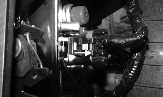
Ignition Switch
The ignition switch, dash switches, front accessory connectors, and front switched accessory connector can be accessed from under the dash.
VOLTAGE NOTE: Perform this test on the harness connector.
1.Set the meter selector to the DC Voltage position. 2.Connect the red meter lead to the red wire; then connect the black meter lead to battery ground. 3.Meter must show battery voltage. NOTE: If the meter shows no battery voltage, trou-
bleshoot the main 30-amp fuse, the battery, or the main wiring harness.
4.Connect the red meter lead to the brown/black wire; then with the black lead grounded, turn the ignition switch to the ON position. The meter must show battery voltage. 5.Connect the red meter lead to the yellow/green wire; then with the black lead grounded, depress the brake, and turn the ignition switch to the START position.
The starter should engage and the meter must show battery voltage. NOTE: When the starter is engaged, battery voltage
will be approximately 10.5 DC volts.
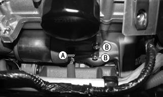
Ignition Coils
The ignition coils (A) are attached to the valve cover with two fasteners per ignition coil.

WT405
RESISTANCE
CAUTION
Always disconnect the battery when performing resistance tests to avoid damaging the multimeter.
NOTE: The following test should be made using
MaxiClips and the Fluke Model 77 Multimeter set to OHMS scale.
1.Disconnect an ignition coil connector. 2.Connect the red tester lead to one coil terminal; then connect the black tester lead to the other coil terminal. Primary coil resistance must be 1.19-1.61 ohms.

SNO-655
3.Connect the red meter lead to one of the terminals; then connect the black meter lead to the bottom of the coil. Secondary coil resistance must be 8500-11500 ohms.

SNO-656
4.Repeat the test on the other two ignition coils. NOTE: If resistance is not within specification, the
coil must be replaced.
Accessory Receptacle/Connector
NOTE: This test procedure is for either the recepta-
cles or the connectors.
VOLTAGE (Switched) 1.Turn the ignition switch to the ON position; then set the meter selector to the DC Voltage position. NOTE: There are three black terminals and 3
orange/black terminals that are connected to their respective colors.
2.Connect the red tester lead to the orange/black wire; then connect the black tester lead to ground. 3.The meter must show battery voltage. NOTE: If the meter shows no battery voltage, trou-
bleshoot the battery, SW. ACC fuse, SW. ACC relay, receptacle, connector, or the main wiring harness.
VOLTAGE (Constant) 1.Set the meter selector to the DC Voltage position. 2.Connect the red tester lead to the red/white wire; then connect the black tester lead to ground. 3.The meter must show battery voltage. NOTE: If the meter shows no battery voltage, trou-
bleshoot the battery, fuse, receptacle, connector, or the main wiring harness.
Switches
SEAT BELT LIMITER NOTE: This vehicle is equipped with a speed limita-
tion device to limit the speed if the operator’s seat belt is not fully engaged. The seat belt indicator light will remain illuminated until the operator’s seat belt is fully engaged.
Resistance 1.Set the meter to the OHMS position. 2.Remove the driver’s seat. Locate the switch connector; then disconnect the connector.

XX330
3.Buckle the driver’s seat belt. On the switch side of the connector, connect one meter lead to one pin and the other meter lead to the opposite connector pin.

MOD485
4.Meter reading should show less than one ohm. 5.Release the seat belt latch from the buckle, with the meter leads still connected to the pins. Meter reading should show OL.
NOTE: If the meter readings are OL or greater than
one ohm with the seat belt buckled, replace the buckle switch assembly. If the resulting readings from step 5 are not OL, replace the buckle switch assembly.
Voltage 1.Set the meter selector to the DC Voltage position. 2.On the harness side of the switch connector, connect the red meter lead to the orange wire and the black meter lead to the tan wire.
3.With the ignition switch in the ON position, the meter should show battery voltage. NOTE: If voltage is not present, check the 10-amp
power fuse, battery/battery connections, or related wires in the battery circuit.
Removing To replace the switch, the driver’s side buckle assembly must be replaced. As the switch is incorporated into the assembly. 1.Remove the driver’s seat and the battery access panel. 2.Remove the cap screw and lock nut securing the buckle cable to the frame.
XX330A
3.Disconnect the switch connector from the switch and remove any nylon straps securing the switch.
Installing 1.Place the new buckle assembly into position; then secure using a new cap screw and lock nut. Tighten to 60 ft-lb (81.6 N-m). 2.Connect the switch and secure to the frame; then install the driver’s seat and the battery access panel.
Component data can be retrieved using the CATT II. Utilize the Sensor Data screen.
NOTE: There are two brake switches on the master
cylinder. The frontmost brake switch is a 12-volt DC circuit switch and is connected to the front brakes. The rearmost brake switch is a switch-to-ground circuit and is connected to the rear brakes.
Voltage Master Cylinder Frontmost Brake Switch NOTE: The ignition switch must be in the ON posi-
tion.
1.Set the meter selector to the DC Voltage position. 2.Connect the red tester lead to the orange wire; then connect the black tester lead to battery ground.

XX341
3.The meter must show battery voltage. NOTE: If the meter shows no battery voltage, trou-
bleshoot the battery, fuse, switch, or the main wiring harness.
NOTE: If the meter shows battery voltage, the main
wiring harness is good; proceed to test the switch/component, the connector, and the switch wiring harness for resistance.
Resistance
CAUTION
Always disconnect the battery when performing resistance tests to avoid damaging the multimeter.
NOTE: There are two brake switches on the master
cylinder. The frontmost brake switch is a 12-volt DC circuit switch and is connected to the front brakes. The rearmost brake switch is a switch-to-ground circuit and is connected to the rear brakes.
NOTE: The brake pedal must be depressed for this
test.
1.Set the meter selector to the OHMS position.
Remove the connectors from the switches.
2.Connect the red tester lead to one terminal spade; then connect the black tester lead to the other terminal spade.

XX341A
3.When the lever is depressed, the meter must show less than 1 ohm; then repeat for other brake switch. NOTE: If the meter shows more than 1 ohm of resis-
tance, replace the switch.
DRIVE SELECT
Resistance
Component data can be retrieved using the CATT II. Utilize the Sensor Data screen.
1.Remove the switch assembly from the dash; then disconnect the harness from the switch.
NOTE: The switch can be removed from the dash
using a thin, flat pry bar or suitable putty knife. It is not necessary to remove the dash to remove the switch.
2.Set the meter selector to the OHMS position, the following readings must be observed:
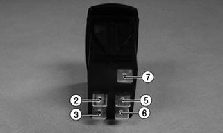
MOD322
Drive Select Switch Drive Select Switch WIRE COLOR 2WD 4WD LOCK
Red tester lead to 12.0 DC Volts 12.0 DC Volts12.0 DC Volts
Orange Red tester lead to 11.5 DC Volts 0 DC Volts 11.5 DC Volts
White/Green Red tester lead to 11.5 DC Volts 0 DC Volts 0 DC Volts
White/Orange
2WD 4WD LOCK
2 to 3 Open (OL) 2 to 3 <1 ohm 2 to 3 <1 ohm 2 to 6 Open (OL) 2 to 6 Open (OL) 2 to 6 <1 ohm 3 to 6 Open (OL) 3 to 6 Open (OL) 3 to 6 <1 ohm
Voltage NOTE: Voltage tests must be made with the switch
and the actuator connected. The meter can be connected at the actuator connector using a break-out harness or MaxiClips. The front drive actuator must be connected.
1.Connect the black tester lead to the black wire; then turn the ignition switch to the ON position. 2.Select the DC Volts position on the tester and observe the meter readings for each switch positions.
NOTE: If the meter does not show voltages accord-
ing to the chart, make sure the front drive actuator is plugged in; then troubleshoot the switch, ignition fuses, battery connections, or wiring harness.
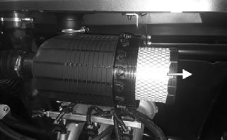
Fan Motors
Component data can be retrieved using the CATT II. Utilize the Sensor Data screen.
NOTE: Preliminary checks may be performed on
this component using the diagnostic mode on the LCD gauge (see Gauge Diagnostic Menu in this section).
NOTE: To determine if the fan motors are good,
connect the red wire from the fan connector to the positive side of a 12-volt battery; then connect the black wire from the fan connector to the negative side. The fan should operate.
XX329
! WARNING
Care should be taken to keep clear of the fan blades.
NOTE: Fan motor resistance checks are not recom-
mended. Resistance values change with the motor commutator position.
NOTE: With the engine stopped and the ignition
switch in the ON position, a momentary “whirring” sound must be noticeable each time the drive select switch is moved to 2WD and 4WD. Test the switch, 30-amp fuse, and wiring connections prior to testing the actuator.
VOLTAGE 1.Locate the 4-wire connector for the front drive actuator above the differential; then connect the red meter lead to the orange wire using a MaxiClip. 2. Connect the black tester lead to the black wire using a
MaxiClip; then select 2WD on the drive select switch. NOTE: The black tester lead can remain connected
to the black wire for the remaining tests.
3.Turn the ignition switch to the ON position. The meter must show battery voltage. NOTE: If battery voltage is not shown, troubleshoot
the fuses in the power distribution module, the ignition switch, or the main wiring harness.
4.Connect the red meter lead to the white/green wire.
The meter must show battery voltage. 5.Select 4WD on the drive select switch. The meter must show 0 DC volts.
6.Connect the red meter lead to the white/orange wire.
The meter must show battery voltage. 7.Select LOCK on the drive select switch. The meter must show 0 DC volts.
Lights
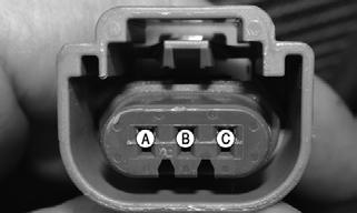
Each headlight has two connectors. one HI/LO (Headlights) three-pin connector and one accent light two-wire connector.
VOLTAGE (Headlights) NOTE: The HI/LO bulb-connector uses a three-pin
connector with the corresponding color codes: white, yellow/black, and black.
1.Behind the headlight remove the inner most connector from the headlight; then set the meter selector to the DC Voltage position.

XX333
XX334
2.Connect the black meter lead to the black wire (B); then connect the red meter lead to the white wire (C); then turn the key switch to the on position and turn the light switch to low beam. Voltage must be present. If no voltage is present, troubleshoot the
LO-BEAM fuse, or lights switch. 3.Connect the black meter lead to the black wire (B); then the red meter lead to the yellow/black wire (A); then turn the key switch to the on position and turn the light switch to the high beam. Voltage must be present. If no voltage is present, troubleshoot the
HI-BEAM fuse, or lights switch. NOTE: If both high beam and low beam have no
voltage, check the lights relay, main fuse, lights switch, battery connections, or wiring harness.
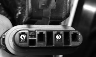
VOLTAGE (Accents) NOTE: The Accent connector uses two-wires in a
three-pin connector with the corresponding color codes: white/red, and black.
1.Behind the headlight remove the outer most connector from the headlight; then set the meter selector to the DC Voltage position.
XX335
XX336
2.Connect the black meter lead to the black wire (B); then connect the red meter lead to the white/red wire (A). then turn the key switch to the on position and turn the light switch to the lights position. Then repeat the test for low beam and high beam. Voltage should be present. NOTE: If no voltage is present on any setting (lights,
low beam, high beam) check the lights fuse, lights switch, battery connections, battery, wiring harness, lights relay. If no voltage is present on certain light switch settings, check lights switch.
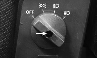
RESISTANCE (Headlight Switch) 1.Remove the plug from the center of the light switch; then remove the screw through the hole; then remove the nut securing the light switch to the dash; then remove the switch assembly from the back side of the dash; then disconnect the harness from the switch.
XX323 XX324
2.Set the meter selector to the OHMS position, the following readings must be observed.
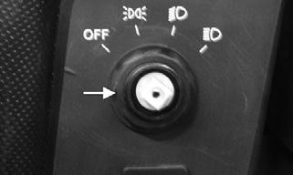

MOD487
LIGHT Switch
A B C D
OFF Open Open Open Open
LIGHTS <1 ohm <1 ohm Open Open LOW BEAM <1 ohm <1 ohm Open <1 ohm HIGH BEAM <1 ohm <1 ohm <1 ohm Open
VOLTAGE (Taillight) NOTE: Perform this test at the socket end of the
taillight-brake light harness (pigtail). The ignition switch must be in the ON position and either the lights, high beam or low beam selected on the light switch.
1.Set the meter selector to the DC Voltage position. 2.Connect the black tester lead to the black wire; then connect the red tester lead to the white/red wire.
3.With the ignition key in the on position and the lights on, the meter must show battery voltage. NOTE: If battery voltage is not shown and the head-
lights are illuminated, inspect the lights fuse. If battery voltage is shown on the meter, replace the bulb.
VOLTAGE (Brake Light) NOTE: Perform this test at the socket end of the
taillight-brake light harness (pigtail). The ignition switch must be in the ON position.
1.Set the meter selector to the DC Voltage position. 2.Connect the red tester lead to the red/blue wire; then connect the black tester lead to the black wire.
3.With the brake applied, the meter must show battery voltage. NOTE: If the meter shows no voltage, inspect the
10-amp lights fuse, brake light switch, wiring harness, or connectors.
Power Distribution Module (PDM)
NOTE: The module and wiring harness are not a
serviceable component and must be replaced as an assembly.
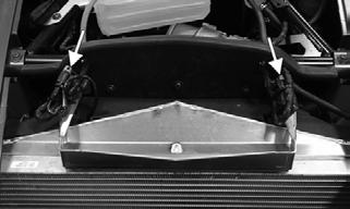
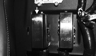
The fuses, relays, and a resistor are located in two separate power distribution modules under the battery access cover between the seats. If there is any type of electrical system failure, always check the fuses first.

XX125
The four-pin relays are identical plug-in type located on the power distribution module. Relay function can be checked by switching relay positions. The four-pin relays are interchangeable. NOTE: To access fuses and relays, compress the
locking tabs on either side of the PDM cover and lift off.
NOTE: The PDM base and wiring harness are not a
serviceable component and must be replaced as an assembly.
1.Remove a fuse from the power distribution module. 2.Set the meter selector to the DC Voltage position. 3.Connect the black tester lead to ground. 4.Using the red tester lead, contact each end of the fuse holder connector terminals individually. 5.The meter must show battery voltage on one fuse terminal but not the other.
NOTE: Battery voltage will be indicated from only
one side of the fuse holder connector terminal; the other side will show no voltage.
NOTE: When testing the HI-BEAM fuse holder, the
headlight switch must be in the high beam position; when testing the LO-BEAM fuse holder, the headlight dimmer switch must be in the low beam position.
NOTE: If the meter shows no battery voltage, trou-
bleshoot the battery, switches, power distribution module, or the main wiring harness.

6411-050

6411-051
This vehicle uses automotive-style (see-through) fuses. The fuses can be visually inspected; replace fuse if link is open.
CAUTION
Always replace a blown fuse with a fuse of the same type and rating.
Component data can be retrieved using the CATT II. Utilize the Sensor Data screen.
NOTE: Make sure the fuses are returned to their
proper position according to amperage. Refer to the amperage listed under each fuse on the power distribution module.
EFI Sensors/Components
THROTTLE BODY
NOTE: Throttle position sensor values are visible in
the diagnostic menu of the gauge.
NOTE: A multimeter cannot be used to diagnose the
throttle body.
The throttle body is not serviceable and must be replaced as an assembly. There are two throttle position sensors for the throttle body. If one sensor fails, the vehicle will have a code(s) that will appear and the engine will be RPM limited until the issue is fixed.
There is no learn mode that is specific to throttle body replacement. When the key is switched to the ON position, the throttle body will quickly verify proper movement. If the key is switched on and left on for 15 seconds or more without starting the engine, the throttle body will go through a full verification process that will be completed once the throttle body stops making noise.
NOTE: If there are any types of idle or run quality
issues, allow the throttle body to go through the full verification process by leaving the key switched on and left for a minimum of 15 seconds without starting the engine. The full verification process is completed when the throttle body stops making noise.
NOTE: The throttle body will not go through the
full verification process if the temperature is < 0° C (< 32° F).
! WARNING
Short drives with this vehicle in freezing temperatures, or rapid hot/freezing cycles, may allow ice to form in the throttle body that can cause run issues. This possibility can be greatly reduced if the engine is allowed to always come to full running temperature when used in below freezing < 0° C (< 32° F) conditions.
THROTTLE PEDAL NOTE: Throttle pedal values are visible in the diag-
nostic menu of the gauge.
The throttle body is not serviceable and must be replaced as an assembly. There are two throttle sensors for the throttle pedal. If one sensor fails the vehicle will have a code(s) that will appear and the engine will be RPM limited until the issue is fixed.
The pedal can come apart, but will not go back together. There is no learn mode for throttle pedal replacement. The throttle pedal sends a 0-100% signal to the ECM.
FUEL INJECTORS NOTE: When attempting to start the engine, the
injectors will send fuel a limited amount of times if the engine has not started.
Resistance
CAUTION
Always disconnect the battery when performing resistance tests to avoid damaging the multimeter. Component data can be retrieved using the CATT II. Utilize the Sensor Data screen.
NOTE: The following test should be made using
MaxiClips and the Fluke Model 77 Multimeter set to OHMS scale.
1.Disconnect the fuel injector wiring harness. 2.Test between the two injector terminals. Resistance must be 11.4-12.6 ohms.
CRANKSHAFT POSITION (CPS) SENSOR Resistance 1.Disconnect the crankshaft position sensor that is located in the driver side rear inner fender next to the regulator/rectifier (A). Set the meter selector to the
OHMS position. 2.Connect the red tester lead to the gray wire on the sensor side; then connect the black tester lead to the black wire on the sensor side.
XX332
3.The meter reading must be approximately 200 ohms.
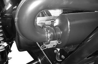
OXYGEN (O2) SENSOR
The oxygen sensor (O2 sensor) is located in the exhaust pipe. NOTE: When testing the resistance of the sensor’s
heater, the engine/exhaust pipe must be at room temperature (65-75° F, 18-24° C) or inaccurate readings will occur.
1.Remove the cargo box. 2.Disconnect the oxygen sensor that is located on the driver side portion of the inner fender.
XX331
3. Set the meter selector to the OHMS position
4.On the sensor side of connector, connect the black (negative) test lead to one white wire pin; then connect the red (positive) test lead to the other white wire pin.
The reading is typically 15.9 ohms. NOTE: If the meter does not read as specified,
replace the sensor.
Component data can be retrieved using the CATT II. Utilize the Sensor Data screen.
Component data can be retrieved using the CATT II. Utilize the Sensor Data screen.
NOTE: Preliminary checks may be performed on
this component using the diagnostic mode on the LCD gauge (see Gauge Diagnostic Menu in this section).
1.Disconnect the connector from the sensor located on top of the intake.

XX328
2.Select DC Voltage on the tester and turn the ignition switch to the ON position. 3.Connect the black tester lead to the black/blue wire and the red tester lead to the pink/violet wire. The meter should read 4.5-5.5 DC volts. If the meter does not read as specified, check the ECM connector or wiring.
ENGINE COOLANT TEMPERATURE (ECT) SENSOR
NOTE: Preliminary checks may be performed on
this component using the diagnostic mode on the LCD gauge (see Gauge Diagnostic Menu in this section).
1.Disconnect the connector from the sensor located below the intake (A) in the thermostat housing (B); then remove the engine coolant temperature (ECT) sensor.
NOTE: When removing sensor, coolant will come
out.
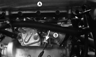
XX327
2.Set the meter selector to the OHMS position; then connect one lead to an outer spade terminal; then connect the other lead to the other outer spade terminal; then suspend the sensor and a thermometer in a container of cooking oil; then heat the oil. NOTE: Neither the sensor nor the thermometer
should be allowed to touch the bottom of the container or inaccurate readings will occur. Use wire holders to suspend the sensor and thermometer.
! WARNING
Wear insulated gloves and safety glasses. Heated oil can cause severe burns.
3.If the readings are not approximately as indicated, the sensor must be replaced.
4.Install the sensor and tighten securely; then connect the connector to the sensor.
5.Fill the cooling system as necessary.
TEMPERATURE OHMS
40° C (104° F) 1128-1144 100° C (212° F) 151-159
ENGINE OIL PRESSURE SWITCH The switch is normally closed when the engine is not running or does not have sufficient oil pressure. The switch becomes open at approximately 19.3 kPa (2.8 psi). 1.Disconnect the connector from the engine oil pressure switch located next to the engine oil filter.

XX325

XX326
2.Set the meter selector to the OHMS position; then connect the red tester lead to the pin inside the switch and the black tester lead to a ground. The switch should have less than 1 ohm of resistance.
3.Start the engine the switch should now be open and the multimeter should read OL. If the switch does not open, verify engine oil pressure is greater than 19.3 kPa (2.8 psi). If engine oil pressure is greater than 19.3 kPa (2.8 psi), replace the engine oil pressure switch.
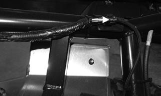
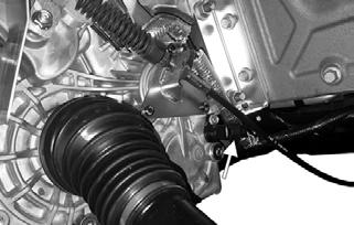
SPEED SENSOR NOTE: Prior to testing the speed sensor, inspect the
three-wire connector on the speed sensor for contamination, broken pins, and/or corrosion.
XX247A
Voltage 1.Set the meter selector to the DC Voltage position. 2.With appropriate needle adapters on the meter leads, connect the red tester lead to the orange wire; then connect the black tester lead to the black/yellow wire.
3.Turn the ignition switch to the ON position. 4.The meter will typically show battery voltage. 5.Leave the black tester lead connected; then connect the red tester lead to the pink/white wire. 6.Slowly move the vehicle forward or backward; the meter must show 0 and battery voltage alternately.
Replacing 1.Disconnect the three-wire connector from the speed sensor; then remove the cap screw securing the sensor to the sensor housing. 3.Install the new speed sensor into the housing with new O-ring lightly coated with multi-purpose grease; then secure the sensor with the cap screw (threads coated with blue Loctite #242). Tighten securely.
XX247A
FUEL PUMP/FUEL LEVEL SENSOR
Component data can be retrieved using the CATT II. Utilize the Sensor Data screen.
The fuel pump and fuel level sensor are not serviceable components. If either component fails, it must be replaced.
Testing
! WARNING
Whenever any maintenance or inspection is made on the fuel system during which there may be fuel leakage, there should be no welding, smoking, open flames, etc., in the area.
AT THIS POINT
Prior to removing the electric fuel pump, the following check should be performed to determine that removal is necessary.
1.Turn the ignition switch ON and listen for a momentary “whirring” sound of the pump building pressure.
If the sound is heard (several seconds), no electrical checks are necessary. Turn the ignition switch OFF.
2.Remove the passenger seat; then disconnect the fuel pump electrical connector (A); then disconnect the fuel hose (B) from the fuel pump; then install the EFI
Fuel Pressure Test kit.
! WARNING
Fuel may be under pressure. De-pressurize the fuel system by disconnecting the fuel pump electrical connector (A) and running the engine until it stalls. Place an absorbent towel around the connector to absorb any fuel when disconnecting.
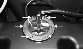
4.Mark the fuel pump mounting and gas tank for installing purposes; then remove the cap screws securing the fuel pump to the gas tank and remove the fuel pump.
CAUTION
Take care not to damage the float or float arm or replacement of the entire assembly will be necessary.

XX342
3.Reconnect the fuel pump electrical connector (A); then turn the ignition switch to the ON position. The fuel pressure should build until the pump shuts off.
Pressure should read 3.0 kg-cm2 (43.5 psi). 4.If the pump is not running, disconnect the fuel pump/sensor connector (A). 5.Connect a multimeter to the power supply leads with the red tester lead to the orange/red wire and the black tester lead to the black wire; then turn the ignition switch to the ON position. The meter should read battery voltage. If battery voltage is indicated and the fuel pump does not run, replace the pump assembly. If no battery voltage is indicated, check the ECM, fuel relay, fuse, and the vehicle tilt sensor.
Removing Fuel Pump Assembly 1.Remove the key from the ignition switch. ! WARNING
Always ensure that power cannot be inadvertently applied to the ignition/ECM when working on the fuel system. If the ignition switch is turned on, the electric fuel pump will start and gas could be rapidly pumped and spilled resulting in fire and severe injury.
2.Remove the passenger seat; then disconnect the negative battery cable. 3.Disconnect the electrical plug (A) from the main harness; then disconnect the fuel hose (B) from the fuel pump.
XX342A
5.Using duct tape or other suitable means, cover the fuel pump opening.
Inspecting AT THIS POINT
If the pump has failed earlier test and must be replaced, proceed to INSTALLING.
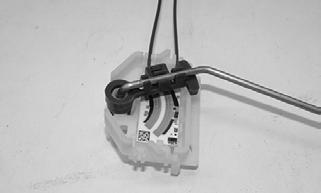
1.Inspect the fuel screen and blow clean with low pressure compressed air. 2.Move the float lever and check for free movement.
The float assembly should return to the lower position without force.
3.Test the fuel level sensor by connecting a multimeter (A) to the fuel level sensor leads (B); then select OHMS. The multimeter should show 5 ohms at full fuel position (C) and 95 ohms at empty fuel position (D).
XX342 ATV2116
NOTE: If readings are erratic, clean the resistor
wiper and resistor with clean alcohol and retest. If still not correct, replace the fuel pump assembly.
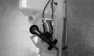
Replacing Fuel Level Sensor To replace the fuel level sensor, use the following procedure.
1.Cut the two blue wires (A) in the location shown.
XR257A
3.Keeping the float attached to the float arm, remove the float arm from the existing fuel level sensor.
Press the float arm into the new fuel level sensor assembly. Ensure it locks into place.

XM366
NOTE: Inspect the float for any damage or leaking
by submerging in water and looking for any air bubbles. Replace if damaged.
4.Install the fuel level sensor assembly onto the fuel pump assembly housing. Once inserted, press down to make sure it locks into place.
MOD482
5.Connect the blue wires using the supplied splice connectors from the fuel level sensor kit. Secure the wires.
Installing Fuel Pump Assembly 1.Place the fuel pump assembly into the fuel tank with a new gasket aligning the match marks; then secure with the cap screws. NOTE: It is important to install the fuel pump with
the correct orientation to ensure adequate float lever clearance.
2.Connect the fuel hose and connect the return fuel hose; then connect the electrical plug to the main harness.
3.Connect the negative battery cable; then turn the ignition switch to the ON position and verify that no fuel leaks are present, the pump runs for several seconds, and the fuel gauge reading is normal. 4.Start the engine to verify proper engine operation; then shut off the engine and verify there are no leaks.
TILT SENSOR ! WARNING
Incorrect installation of the tilt sensor could cause sudden loss of engine power which could result in loss of vehicle control resulting in injury or death.
CAUTION
Do not drop the tilt sensor as shock can damage the internal mechanism.
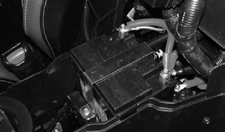
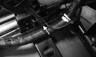
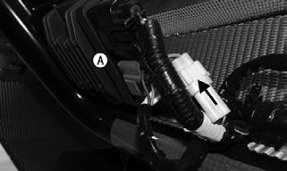
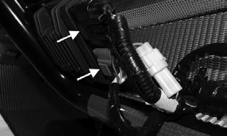
Supply Voltage 1.The tilt sensor (A) is located underneath the battery access cover behind the battery (B). Disconnect the three-wire connector from the sensor; then select DC
Voltage on the multimeter and connect the red tester lead to the orange wire and the black tester lead to the violet/black wire.

XX337

XX338
2.Turn the ignition switch to the ON position. The multimeter should read battery voltage. If battery voltage is not indicated, check the 20-amp EFI relay, the 10-amp EFI fuse in the PDM, wiring harness, or the ignition switch.
3.Remove the red tester lead and connect to the blue/brown wire. The multimeter should read less than 0.2 DC volts. If the specified voltage is not indicated, check wire connections at the ECM or substitute another ECM to verify the test.
Output Voltage NOTE: Needle adapters will be required on the mul-
timeter leads as the following tests are made with the sensor connected.
1.Connect the three-wire plug to the sensor; then remove one of the mounting screws securing the sensor.
XX337A

XX338A
2.Install the needle adapters to the multimeter leads; then select DC Voltage on the multimeter. 3.Connect the red tester lead to the blue/brown wire and the black tester lead to the violet/black wire; then turn the ignition switch ON and observe the meter.
The meter should read 0.3-1.5 DC volts.
4.Tilt the sensor 60° or more to the left and right while observing the meter. The meter should read 3.0-7.0
DC volts after approximately one second in the tilted position. If the meter readings are not as specified, the tilt sensor is defective.


XX338B
NOTE: When replacing the sensor after testing,
make sure the arrow marking is directed up.
Starter Motor
The starter is located below the engine oil filter. NOTE: The starter motor is not a serviceable com-
ponent. If the starter is defective, it must be replaced.
REMOVING 1.Disconnect the battery; then remove the rear skid plate and engine cover.
2.Remove the nut (A) securing the positive cable to the starter; then remove the cable from the starter; then remove the two cap screws (B) securing the starter; then remove the starter.
CAUTION
Always disconnect the negative battery cable from the battery first; then disconnect the positive cable.
XX339
INSTALLING 1.Install the starter. Secure with two cap screws (B) with blue Loctite #243. Tighten to 19 ft-lb (25.8 N-m); then install the positive cable to the starter and secure with nut (A).


XX339
2.Install the rear skid plate and engine cover: then connect the battery.
TESTING VOLTAGE Perform this test on the starter positive terminal. NOTE: The ignition switch must be in the ON posi-
tion, and the shift lever in the PARK position.
1.Set the meter selector to the DC Voltage position. 2.Connect the red tester lead to the starter terminal (A); then connect the black tester lead to ground.

XX339A
3.With the brake depressed and key switch momentarily held in the start position, the meter must show battery voltage and the starter should operate.
NOTE: If the meter shows correct voltage but the
starter motor does not operate or operated slowly, troubleshoot all starting system components before replacing the starter motor.
NOTE: If the meter shows no battery voltage,
inspect the main fuse, ground connections, starter lead, battery voltage (at the battery), starter relay, or the start relay.
Starter Relay
1.Remove the battery access panel; then using the multimeter set to the DC Voltage position, check the starter relay that is located behind the battery as follows. 2.Connect the red tester lead to the positive battery terminal; then connect the black tester lead to the start relay connection (A) on the starter relay. The meter must show battery voltage.
XX340
NOTE: Make sure the ignition switch is in the ON
position and the transmission in park.
3.With the brake pedal depressed, rotate the key switch to the starter position while observing the multimeter. The multimeter should drop to 0 volts and a
“click” should be heard from the relay. NOTE: If a “click” is heard and more than one volt
is indicated by the multimeter, replace the starter relay. If no “click” is heard and the multimeter continues to indicate battery voltage, proceed to step 4.
4.Disconnect the two-wire plug from the starter relay; then connect the red tester lead to the green wire and the black tester lead to the orange wire.
XX340A
5.With the brake pedal depressed and the key switch momentarily held in the start position, observe the multimeter.
NOTE: If constant battery voltage is indicated,
replace the starter relay.
Alternator/Regulator/ Rectifier/Stator
There are two ways that electrical power is generated to the battery. The battery receives a charge from the alternator that is externally attached to the engine on the passenger side and from the stator. The stator is internal on the engine and feeds the regulator/rectifier. The regulator/rectifier is attached to the frame on the passenger side rear inner fender. To accurately test the alternator and/or stator (regulator/rectifier), they must be isolated from each other. ALTERNATOR Testing NOTE: Prior to performing the following test, make
sure the alternator belt is properly tightened and the battery is fully charged.
1.Disconnect both of the electrical connections going to the regulator/rectifier.
XX332A
2.Using a suitable multimeter, select the DC Voltage position; then connect the red tester lead to the positive battery post and the black tester lead to the negative battery post. Note the voltage with the engine not running. 3.Start the engine. The voltage should increase with the engine running. Typically with the engine at idle it is around 14.5 DC volts with minimal electrical components “on” (accessories, fans, etc.). The maximum volts can be up to 15.5 DC volts. NOTE: If voltage rises above 15.5 DC volts, the reg-
ulator is faulty or a battery connection is loose or corroded. Clean and tighten battery connections or replace the alternator. If voltage does not rise, check all battery connections, the battery wire on the alternator, and the voltage regulator wire. If all are normal, replace the alternator.
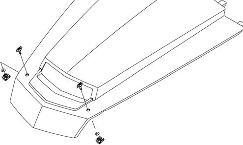
Removing 1.Disconnect the negative battery cable from the battery; then remove the four cap screws securing the alternator belt cover and account for the washer and spacer from each; then remove the alternator belt cover downwards from the passenger rear inner fender.

XX366

XX367
XX368
2.Disconnect the battery wire from the back side of the alternator; then disconnect the electrical connector from the backside of the alternator.

XX369
3.Loosen the alternator adjuster cap screw (A) and the pivot bolt (B); then remove the alternator belt.

XX370
4.Remove the adjuster cap screw and pivot bolt and remove the alternator.
NOTE: The alternator/regulator is not a serviceable
part; therefore, it must be replaced as an assembly.
Installing 1.Place the alternator into position on the engine; then secure with the existing hardware. Do not tighten at this time.
2.Place the alternator belt into position; then using a suitable pry, tension the belt so that with a good belt it does not spin on the pulley or make noise.
3.Holding tension on the belt, tighten the adjuster cap screw (A) securely; then remove the pry and tighten the pivot bolt (B) securely.
XX370
4.Connect the battery wire and connect the voltage regulator connector; then install the alternator belt cover; then reinstall the four cap screws with washers and spacers; then tighten securely; then connect the negative battery cable to the battery.
REGULATOR/RECTIFIER (Stator-Powered) Testing NOTE: Prior to performing the following test, make
sure the battery is fully charged.
1.Remove the resistor in the power distribution module (PDM) beneath the battery access cover.
XX125A
2.Using a suitable multimeter, select the DC Voltage position; then connect the red tester lead to the positive battery post and the black tester lead to the negative battery post. Note the voltage with the engine not running 3.Start the engine. The voltage should increase with the engine running. Typically with the engine at idle it is around 14.0 DC volts with minimal electrical components “on” (accessories, fans, etc). The maximum volts can be up to 15.5 DC volts. NOTE: If voltage rises above 15.5 DC volts, the regula-
tor is faulty or a battery connection is loose or corroded. Clean and tighten battery connections. If voltage does not rise, check all battery connections, the connections on the regulator/rectifier, and the stator.
STATOR Testing
! WARNING
Most voltages generated by the stator system are sufficient to interrupt heart pacemakers! All technicians, especially those using pacemakers, must avoid contact with all electrical connections after the engine has been started.
1.Disconnect the gray connector from the regulator/rectifier.

XX332B
2.Using a suitable multimeter, select the AC Voltage position; then test between the three yellow wires for a total of three tests. 3.With the engine running at 2500-3000 RPM, all wire tests must be within 36-44 AC volts. NOTE: If tests failed, check all connections, etc., and
test again. If no voltage is present, replace the stator assembly.
Electronic Control Module (ECM)
The ECM is located above the battery beneath the battery access panel. NOTE: The ECM is not a serviceable component. If
the unit is defective, it must be replaced.
The ECM is rarely the cause for electrical problems; however, if the ECM is suspected, substitute another ECM to verify the suspected one is defective. This system has a built-in feature that will only allow an ECM of the same part number to be used in this model. Do not attempt to substitute an ECM from a different model as the system will not allow it to start. Error codes can be cleared by following the procedures located in the Gauge Diagnostic Menu sub-section in this section.
Gauge Diagnostic Menu
DIGITAL GAUGE The digital gauge has a diagnostic menu that can be used to diagnose many of the DTCs displayed. To place the gauge into the diagnostic mode, use the following procedure.
NOTE: The digital gauge has four buttons: upper
left (A), upper right (B), lower left (C), and lower right (D).

XX352
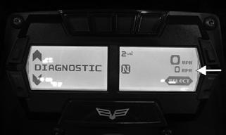
1.Turn the ignition switch ON. 2.Depress and hold either both the lower left (C) and lower right (D) or the upper right (B) and lower right (D) buttons together for approximately three seconds until “DIAGNOSTIC” appears on the LCD.

XX351
3.Press the center button (SELECT) (lower right button (D)) to enter diagnostic mode; cycle the display by pressing either the left or right button to step to the desired function.
NOTE: The gauge can be utilized dynamically
(engine running/vehicle moving) or statically (engine/vehicle stopped).
DIAGNOSTIC MODES Battery (BATTERY VOLTS)
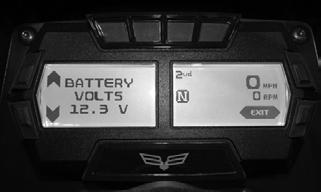
XX343
Display: System DC voltage. DTC: P0562, P0563 Usage: Verify system voltage under following conditions:
1.Battery voltage with engine and accessories off (>12.2 VDC for fully charged). 2.Battery voltage with engine idling (charging = 13.8
VDC or greater). 3.Battery voltage with electrical accessories operating, engine idling (13.5 VDC or greater). 4.Battery voltage starter cranking (10.5-11.5 VDC).
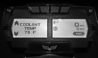
XX344
Display: Engine coolant temperature as measured by the ECT sensor.

DTC: P0116, P0117, P0118, P0217, P0480 P0691, P0692 Usage: Monitor coolant temperature to verify the following: 1.ECT sensor signal. 2.High Temperature indicator (on @ 230° F (110° C), off @ 203° F (95° C). 3.Thermostat starts opening @ approximately 181-189° F (83-87° C), and should be fully open @ approximately 212 °F (100° C) indicated by a momentary drop or pause in the rising temperature reading. 4.Fan ON @ 213° F (100.5° C), OFF @ 203° F (95°
C).
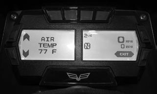
Intake Air Temperature (AIR TEMP)

XX345
Display: Intake air temperature as measured by the Temperature Manifold Absolute Pressure (TMAP) sensor. DTC: P0112, P0113, P0114 Usage: Monitor intake air temperature to verify the following: 1.Intake air temperature sensor signal.
XX347
Display: Air pressure as measured by the Temperature Manifold Absolute Pressure (TMAP) sensor. DTC: P0068, P0107, P0108 Usage: Monitor air pressure to verify the following: 1.Intake air pressure sensor signal.
Throttle Position Sensor (TPS)
XX346
Display: Throttle position sensor percentage as measured by the throttle position sensor from the throttle body. DTC: P0068, P0122, P0123, P0222, P0223, P1120, P1121, P1122, P1123, P1124, P1125, P1126, P2135 Usage: Monitor throttle percentage to verify the following while the vehicle is running: 1.Throttle position sensor signal from throttle body. 2.Movement of throttle body via accelerator position sensor (limited movement when vehicle is not running).
Accelerator Position Sensor (PEDAL)

Display: Accelerator position sensor percentage as measured by the accelerator position sensor. DTC: P2122, P2123, P2127, P2128, P2138 Usage: Monitor accelerator position sensor percentage to verify the following: 1.Accelerator position sensor signal.
Brake Switches (BRAKE)
XX349
Display: Brake switch signal from switch 1 (Front) and switch 2 (Rear). DTC: P0504
Usage: Monitor brake switch signal to verify the following: 1.Brake switch signals.

Fuel Sensor (FUEL OHMS)
XX350
Display: Fuel level signal from the fuel level sensor. DTC: C1400
Usage: Check output of the fuel level sensor.* 1.Full fuel is indicated by a reading of 0-5 ohms. 2. Empty is indicated by a reading of 95-105 ohms.
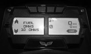
* If a reading of 110-500 ohms, suspect the fuel level sensor or wiring. If a reading of 0-100 ohms but no gauge indication, suspect the gauge.
XX351B
Display: Engine RPM (On the right screen on every diagnostic screen). DTC: P0219, P0370. P0371, P0372, P0373, P0374 Usage: Verify engine speed signal from the following: 1.CPS (crankshaft position) sensor to ECM. 2. ECM (CAN) signal to gauge (tachometer). 3.ECM (CAN) signal to EPS.
Speedometer (MPH/KMH)

XX351A
Display: Vehicle speed signal (On the right screen on every diagnostic screen). DTC: P0500, P0503 Usage: Verify speedometer sensor signal from the following: 1.Speed sensor to ECM. 2.ECM (CAN) signal to gauge (speedometer/odometer). 3.ECM (CAN) signal to EPS.
DIAGNOSTIC TROUBLE CODES (DTC) If a related chassis component fails or an out-of-tolerance signal is detected by the ECM, a diagnostic trouble code (DTC) will be generated in the ECM and displayed on the LCD. The DTC will be displayed alternately with a wrench icon or malfunction indicator light (MIL). The DTC will continue to flash until the malfunction is corrected and the code cleared.
Diagnostic Trouble Codes (DTC)
Code List NOTE: Each of the following numerical codes will
have a one-letter prefix of C, P, or U. A “C” prefix denotes a chassis malfunction, a “P” prefix denotes a power train malfunction, and a “U” prefix denotes a loss of communication with the gauge.
NOTE: Normal malfunction codes are cleared from
the LCD when the component is replaced or the malfunction is corrected; however, intermittent codes must be cleared as noted in the code chart.
NOTE: Low system voltage, loose connections
and/or insufficient cranking speed of the engine can cause codes P0370, P0371, P0372, P0373, P0374
NOTE: If there are several random codes being dis-
played, check the wire harness/connectors.
NOTE: For Electronic Power Steering (EPS) Diag-
nostic Trouble Codes (DTC) see the Electronic Power Steering section.
Display Fault Description Possible Cause Fault Recovery Method
C0063 Tilt Sensor Circuit High Sensor or interconnect harness shorted to battery power. Correct condition* C0064 Tilt Sensor Circuit Low/SG/Open Sensor or interconnect harness open or shorted to chassis ground.Correct condition* C1263 Backup/Reverse Circuit Open The backup/reverse relay has been disconnected or its interconnect Correct condition* harness is open. C1264 Backup/Reverse Buzzer Circuit High The backup/reverse relay or its interconnect harness is shorted to Correct condition* battery power. C1265 Backup/Reverse Circuit Low/SG The backup/reverse relay or its interconnect harness is shorted to Correct condition* chassis ground. C1400 Fuel Level Sensor Circuit Open The fuel level sensor or interconnect harness is open. Correct condition* P0030 Oxygen Heater Intermittent/Open The oxygen heater or its interconnect harness is intermittent or Correct condition* open.
P0031 Oxygen Heater Low/SG
P0032 Oxygen Heater High/SP
The oxygen heater or its interconnect harness is shorted to chassis ground. Correct condition*
The oxygen heater or its interconnect harness is shorted to battery power. Correct condition*
P0068 Throttle Position Sensor MAP Plausibility Check for a vacuum leak or a plugged air filter. P0107 MAP Sensor Circuit Low/SG/Open The MAP sensor or its interconnect harness is shorted to chassis ground. P0108 MAP Sensor Circuit High/SP The MAP sensor or its interconnect harness is shorted to battery power. Correct condition* Correct condition*
Correct condition*
P0112 Intake Air Temp Sensor Circuit Low/SG The intake air-temp sensor or its interconnect harness is shorted to chassis ground. Correct condition*
P0113 Intake Air Temp Sensor Circuit High/Open The intake air-temp sensor or its interconnect harness is open or shorted to battery power. Correct condition*
P0114 Intake Air Temp Sensor Circuit Intermittent
The intake air-temp sensor or its interconnect harness is intermittent. Correct condition*
P0116 Engine Coolant Temp Sensor Circuit Range/Performance P0117 Engine Coolant Temp Sensor Circuit Low/SG P0118 Engine Coolant Temp Sensor Circuit High/Open/SP P0122 Throttle Position Sensor #1 Circuit Low/SG
The engine coolant-temp sensor is producing an out-of-range voltage. The engine coolant-temp sensor or its interconnect harness is shorted to chassis ground. Correct condition*
Correct condition*
The engine coolant-temp sensor or its interconnect harness is open or shorted to battery power. Correct condition*
The throttle position sensor or its interconnect harness is shorted to chassis ground. Correct condition*
P0123 Throttle Position Sensor #1 Circuit High/Open
The throttle position sensor or its interconnect harness is open or shorted to battery power. P0130 Oxygen Sensor Intermittent/Open The oxygen sensor or its interconnect harness is intermittent or open. Correct condition*
Correct condition*
P0131 Oxygen Sensor Low/SG or Air-Leak The oxygen sensor or its interconnect harness is shorted to chassis ground or an air-leak exists. Correct condition*
P0132 Oxygen Sensor High/SP
The oxygen sensor or its interconnect harness is shorted to battery power. Correct condition*
P0171 Oxygen Feedback Below Minimum Correction
Low fuel rail pressure, dirty fuel filter, or dirty injectors. Correct condition*
P0172 Oxygen Feedback Exceeds Maximum Correction
Excessive fuel rail pressure, MAP or temp sensors out-of-spec. Correct condition*
P0201 Cylinder #1 Fuel Injector Circuit Open Injector #1 has been disconnected or its interconnect harness is open. P0202 Cylinder #2 Fuel Injector Circuit Open Injector #2 has been disconnected or its interconnect harness is open. P0203 Cylinder #3 Fuel Injector Circuit Open Injector #3 has been disconnected or its interconnect harness is open.
P0217 Engine Coolant Over Temperature Detected
There may be a malfunction of the cooling system. Correct condition**
Correct condition**
Correct condition**
Correct condition*
P0219 Engine Over-Speed Condition The engine speed (RPM) has exceeded the ECM over-speed setpoint/limit. Reduce engine speed
P0223 Throttle Position Sensor #2 Circuit High The throttle position sensor or its interconnect harness is shorted to battery power. P0261 Cylinder #1 Fuel Injector Circuit Low/SG Injector #1 or its interconnect harness is shorted to chassis ground.Correct condition** P0262 Cylinder #1 Fuel Injector Circuit High Injector #1 or its interconnect harness is shorted to battery power. Correct condition** P0264 Cylinder #2 Fuel Injector Circuit Low/SG Injector #2 or its interconnect harness is shorted to chassis ground.Correct condition** P0265 Cylinder #2 Fuel Injector Circuit High Injector #2 or its interconnect harness is shorted to battery power. Correct condition** P0267 Cylinder #3 Fuel Injector Circuit Low/SG Injector #3 or its interconnect harness is shorted to chassis ground.Correct condition** P0268 Cylinder #3 Fuel Injector Circuit High Injector #3 or its interconnect harness is shorted to battery power. Correct condition** P0363 Misfire Detected — Fueling Disabled There could be a fouled spark plug or poor fuel quality. The ignition Correct condition* (cannot be tripped at idle) coil or fuel injector or their interconnect harnesses could also be malfunctioning. Can be caused by very low fuel.
P0370 Loss of Crankshaft Position Sensor Synchronization/Gap Position
The crankshaft position sensor is not recognizing teeth as expected. Correct condition*
P0371 Crankshaft Position Sensor Additional Teeth Detected
The crankshaft position sensor is not recognizing teeth as expected. Correct condition*
P0372 Crankshaft Position Sensor Missing Tooth The crankshaft position sensor is not recognizing teeth as expected.
P0373 Crankshaft Position Sensor Spike Detected
The crankshaft position sensor is not recognizing teeth as expected. Correct condition*
Correct condition*
P0374 Crankshaft Position Sensor Signal Not Detected
The crankshaft position sensor or its interconnect harness is open or shorted to ground. Correct condition*
P0444 EVAP System Purge Control Valve Circuit Open
The EVAP system purge control valve is disconnected or its interconnect harness is open. Correct condition*
P0458 EVAP System Purge Control Valve Circuit Low/SG
The EVAP system purge control valve or its interconnect harness is shorted to chassis ground. Correct condition*
P0459 EVAP System Purge Control Valve Circuit High/SP
The EVAP system purge control valve or its interconnect harness is shorted to battery power. Correct condition*
P0480 Fan-Primary Relay Control Circuit Open The primary fan relay or its interconnect harness is open. Correct condition* P0481 Fan-Secondary Relay Control Circuit The secondary fan relay or its interconnect harness is open. Correct condition* Open P0500 Vehicle Speed-Sensor The vehicle speed sensor circuit signal is intermittent or missing. Correct condition** P0503 Vehicle Speed Sensor Circuit The vehicle speed sensor circuit or its interconnect harness is open Correct condition** Intermittent/Erratic/High or shorted to battery power. P0504 Brake Switch Priority Brake pressure switch #1 or its interconnect is open or shorted to Correct condition* chassis ground.
P0562 System Voltage Low
The battery charge condition is low or the regulator/rectifier output is low. Correct condition*
P0563 System Voltage High
P0600 Serial Communication Link
The battery cable connections are loose or the regulator/rectifier output is high. The ECM detected an internal condition. Correct condition*
Correct condition*
P0606 Internal Monitoring Error P060C Internal Monitoring 3 Error P0615 Starter Relay Circuit
The ECM detected an internal condition. The ECM detected an internal condition. Correct condition* Correct condition*
The start switch/button, starter relay, gearswitch or its interconnect harness is erratic or intermittent. Correct condition*
P0616 Starter Relay Circuit Low
P0617 Starter Relay Circuit High
The start switch/button, starter relay or its interconnect harness is intermittent or shorted to chassis ground. The start switch/button, starter relay, or its interconnect harness is intermittent or shorted to battery power. Correct condition*
Correct condition*
P061A Internal Monitoring of Torque Error The ECM detected an internal condition. P061F Electronic Throttle Control Driver Temperature Warning
The ECM detected an internal condition. Correct condition* Correct condition*
P0627 Fuel Pump Control Circuit Open The fuel pump control circuit or its interconnect harness is open. Correct condition* P0628 Fuel Pump Control Circuit Low/SG The fuel pump control circuit or its interconnect harness is shorted Correct condition* to chassis ground. P0629 Fuel Pump Control Circuit High/SP The fuel pump control circuit or its interconnect harness is shorted Correct condition* to battery power. P0630 VIN Not Programmed or Incompatible Verify that the LCD gauge and ECM part numbers are correct for Correct condition* the vehicle model number and VIN.
P0641 Sensor Reference Voltage #1 Circuit Low/Open P0643 Sensor Reference Voltage #1 Circuit High P0651 Sensor Reference Voltage #2 Circuit Low/Open
5-volt sensor power circuit #1 has been shorted to chassis ground.Correct condition*
5-volt sensor power circuit #1 has been shorted to battery power. Correct condition*
5-volt sensor power circuit #2 has been shorted to chassis ground.Correct condition*
P0653 Sensor Reference Voltage #2 Circuit High
5-volt sensor power circuit #1 has been shorted to battery power. Correct condition*
P0685 EFI/Main Relay Circuit Open The Main/EFI relay has been removed or its circuit is open. Correct condition* P0686 EFI/Main Relay Circuit Low/SG The Main/EFI relay or its circuit is shorted to chassis ground. Correct condition* P0687 EFI/Main Relay Circuit High/SP The Main/EFI relay or its circuit is shorted to battery power. Correct condition* P0691 Fan-Primary Relay Control Circuit The primary fan relay or its interconnect harness is shorted to Correct condition* Low/SG chassis ground. P0692 Fan-Primary Relay Control Circuit The primary fan relay or its interconnect harness is shorted to Correct condition* High/SP battery power.
The secondary fan relay or its interconnect harness are shorted to ground.
P0694 Fan-Secondary Relay Control Circuit High/SP
The secondary fan relay or its interconnect harness are shorted to battery power. P1120 Throttle Position Sensor Lower Position The electronic throttle valve was unable to cycle through its entire self check range. P1121 Throttle Position Sensor Lower Adaption The electronic throttle valve was unable to cycle through its entire self check range. P1122 Throttle Position Sensor Lower Return The electronic throttle valve was unable to cycle through its entire self check range.
P1123 Throttle Position Sensor Adaption Condition
The electronic throttle valve was unable to cycle through its entire self check range. Correct condition*
Correct condition*
Correct condition*
Correct condition*
Correct condition*
P1124 Throttle Position Sensor Limp Home Adaption
The electronic throttle valve was unable to cycle through its entire self check range. Correct condition*
P1125 Throttle Position Sensor Upper Position The electronic throttle valve was unable to cycle through its entire self check range. P1126 Throttle Position Sensor Upper Return The electronic throttle valve was unable to cycle through its entire self check range. Correct condition*
Correct condition*
P2100 Throttle Actuator Control Motor Circuit Open
The electronic throttle control actuator or its interconnect harness is open. Correct condition*
P2102 Throttle Actuator #1 Control Motor Circuit Low/SG
The electronic throttle control actuator or its interconnect harness is shorted to chassis ground. Correct condition*
P2103 Throttle Actuator #1 Control Motor Circuit High/SP
The electronic throttle control actuator or its interconnect harness is shorted to battery power. Correct condition*
P2106 Electronic Throttle Control Output is Out Of Range P2107 Electronic Throttle Control Driver Over-Temperature
The ECM detected an internal condition.
The ECM detected an internal condition. Correct condition*
Correct condition*
P210C Throttle Actuator #2 Control Motor Circuit Low/SG
The electronic throttle control actuator or its interconnect harness is shorted to chassis ground. Correct condition*
P210D Throttle Actuator #2 Control Motor Circuit High/SP
The electronic throttle control actuator or its interconnect harness is shorted to battery power. Correct condition*
P2118 Throttle Actuator Control Motor Range Error
The electronic throttle control actuator wires or its interconnect harness are shorted together. Correct condition*
P2119 Throttle Control Actuator Control Performance Error
Either the positive or the negative wire of the electronic throttle control actuator or its interconnect harness is open. Correct condition*
P2122 Pedal Position Sensor #1 Circuit Low/Open/SG
The pedal position sensor or its interconnect harness is shorted to chassis ground or open. P2123 Pedal Position Sensor #1 Circuit High/SP The pedal position sensor or its interconnect harness is shorted to battery power.
P2127 Pedal Position Sensor #2 Circuit Low/Open/SG
The pedal position sensor or its interconnect harness is shorted to chassis ground or open. Correct condition*
Correct condition*
Correct condition*
P2128 Pedal Position Sensor #2 Circuit High/SP The pedal position sensor or its interconnect harness is shorted to battery power. Correct condition*
P2135 Throttle Position Sensor Plausibility Error One of the throttle position sensor circuits is shorted to either battery power, ground, is open, or a faulty sensor. P2138 Pedal Position Sensor Plausibility Error One of the throttle position sensor circuits is shorted to either battery power, ground, is open, or a faulty sensor. Correct condition*
Correct condition*
P2299 Brake Pedal Position/Accelerator Pedal Position Incompatible
The brake light pressure switch is active while the accelerator pedal is being depressed. Correct condition*
P2300 Ignition Coil #1 Primary Circuit Low/SG/Open
Ignition coil #1 primary circuit or its interconnect harness is open or shorted to chassis ground. Correct condition**
P2301 Ignition Coil #1 Primary Circuit High Ignition coil #1 primary circuit or its interconnect harness is shorted to battery power. Correct condition**
P2303 Ignition Coil #2 Primary Circuit Low/Open Ignition coil #2 primary circuit or its interconnect harness is open or shorted to chassis ground. Correct condition**
P2304 Ignition Coil #2 Primary Circuit High Ignition coil #2 primary circuit or its interconnect harness is shorted to battery power. Correct condition**
P2306 Ignition Coil #3 Primary Circuit Low/Open Ignition coil #3 primary circuit or its interconnect harness is open or shorted to chassis ground. Correct condition**
P2307 Ignition Coil #3 Primary Circuit High Ignition coil #3 primary circuit or its interconnect harness is shorted to battery power. Correct condition**
P2610 ECU Warm Reset
System voltage may have been temporarily too low to power the ECU. Correct condition*
U0100 Lost Communication with ECM The ECM CAN circuit or its interconnect harness is intermittent or has failed. Correct condition*
U0155 LCD Gauge to ECM CAN Communication Lost FUEL OFFTilt Sensor Activation Code
The LCD gauge CAN circuit or its interconnect harness is intermittent or has failed. The chassis tilt sensor has been activated. Correct condition*
Correct condition*
High: A high voltage condition has been detected. Low: A low voltage condition has been detected. Intermittent: An intermittent circuit condition has been detected. Open: An open circuit condition has been detected. * After correcting the condition, cycle the key switch On-Off-On. **After correcting the condition, cycle the key switch On-Off-On, start the engine and drive vehicle, then cycle the key switch On-Off-On.
Troubleshooting
Problem: Battery does not charge Condition Remedy
1. Battery wires/connections shorted — loose — open 1.Repair — replace — tighten battery wires/connections 2. Alternator belt loose — bad 2.Tighten — replace belt 3. Alternator/regulator failed 3.Replace alternator assembly 4. Stator/regulator/rectifier failed 4.Replace stator — regulator/rectifier
Problem: Charging unstable Condition Remedy
1. Battery wires/connections shorted — loose — open 1.Repair — replace — tighten battery wires/connections 2. Alternator belt loose 2.Tighten — replace belt 3. Alternator/regulator failing 3.Replace alternator assembly 4. Stator/regulator/rectifier failing 4.Replace stator — regulator/rectifier
Problem: Starter does not engage Condition Remedy
1. Battery charge low 1.Recharge — replace battery 2. Switch contacts defective 2.Replace switch 3. Start relay defective 3.Replace start relay 4. Starter relay defective 4.Replace starter relay 5. Wiring connections loose — disconnected 5.Connect — tighten — repair connections 6. Key switch defective 6.Replace key switch
Problem: Battery discharges too rapidly Condition Remedy
1. Battery sulfided 1.Replace battery 2. Electrical system excessively loaded 2.Reduce load 3. Battery short-circuited 3.Replace battery 4. Charging system not charging 4.Replace alternator — stator — regulator/rectifier — tighten alternator belt
Problem: Battery polarity reversed Condition Remedy
1. Battery incorrectly connected 1.Reverse connections — replace battery — repair damage