83 minute read
Drive Train/Track/Brake Systems

This section has been organized into sub-sections for servicing drive train, track, and brake systems; however, some components may vary from model to model. The technician should use discretion and sound judgment when removing and installing components. NOTE: Whenever a part is worn excessively,
cracked, or damaged in any way, replacement is necessary.
SPECIAL TOOLS A number of special tools must be available to the technician when servicing the drive train, track, and brake systems.
NOTE: When indicated for use, each special tool
will be identified by its specific name, as shown in the chart below, and capitalized.
NOTE: Special tools are available from the Arctic
Cat Service Parts Department.
Description
Drive Clutch Bolt Tool Drive Belt Deflection Tool Bearing Removal and Installation Tool Movable Sheave Bearing Tool Clutch Alignment Bar (2000) Clutch Alignment Bar (7000) Drive Clutch Puller Drive Clutch Spanner Wrench Driven Clutch Compressor Tool Rear Suspension Spring Tool Brake Caliper Bearing Puller
p/n
0644-281
0644-424
0644-167
0644-594
0644-496
0744-093
0744-062
0644-136
0644-444
0144-311
0744-067
CAUTION
Never attempt to substitute any other drive clutch puller for the recommended puller or severe clutch damage will occur.
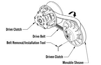
Drive Belt
If the drive belt is longer than specified, the drive clutch and driven clutch will not achieve full shift ratio. This will result in poor acceleration and a decrease in top speed. If the drive belt is shorter than specified, the starting ratio will be higher causing the belt to slip. A too-short drive belt will cause a bog on engagement and will not allow the engine to reach peak RPM. NOTE: A thinly-worn drive belt may produce the
same effect as one that is too long.
NOTE: A stiff belt causes a HP loss to the track. As
a belt warms up, it gets more flexible and transmits power with less HP loss.
NOTE: When installing a new drive belt, see After
Break-In Checkup/Checklist - Drive Belt Break-In in the General Information/Foreword section.
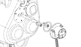
REMOVING (2000) 1.With the engine off, remove the left-side access panel. Loosen the 1/4 turn on the lower console. 2.Remove the cap screw, washers and sheave adjuster from the end of the driven clutch; then remove the cap screw, lock washer, and washer from the adjuster. NOTE: Assure that the shims and O-ring are not
removed from the adjuster.
0743-395
3.Reverse the adjuster and install the cap screw without washers into the adjuster. Install the sheave adjuster and cap screw onto the driven clutch; then tighten the cap screw until the movable sheave opens far enough to allow the belt to be removed. 4.Remove the drive belt from the driven clutch first; then from the drive clutch.
NOTE: Each time the driven clutch cap screw is
removed, the hole in the driven shaft should be cleaned free of any Loctite residue.
INSTALLING (2000) CAUTION
Before securing the driven clutch, be sure the rollers are up against the torque bracket or damage to the back-side cams may occur.
1.Place the drive belt (so the arrow is pointing toward the front of the snowmobile) in the drive clutch; then between the sheaves of the driven clutch.
2.Install the sheave adjuster in its original position (beveled side out); then install the cap screw, lock washer, and washer into the driven clutch. Tighten the cap screw (threads coated with blue Loctite #243) to 20 ft-lb. 3.Secure the left-side console and access panel,
! WARNING
Never operate the snowmobile without the belt guard/access panel secured in place.
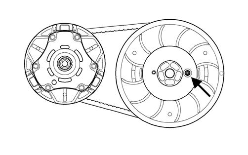
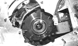
REMOVING (7000) 1.Set the brake lever lock; then remove the left-side access panel. Loosen the 1/4 turn on the lower console.
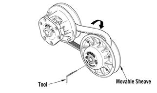
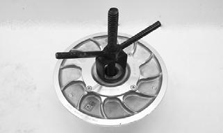
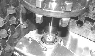
2.Using Drive Belt Deflection Tool, thread the tool clockwise into the driven clutch until the movable sheave opens far enough to remove the drive belt.
743-067B
INSTALLING (7000) 1.Place the belt (so the part number can be read) between the sheaves of the drive clutch.
2.With the sheaves fully apart, roll the belt over the stationary sheave. 3.With the drive belt properly positioned in the drive clutch and driven clutch, turn the belt tool counterclockwise, release the brake lever lock, and roll the belt back and forth to allow the driven clutch sheaves to fully close. 4.After the belt is installed properly, secure the left-side lower console and the access panel.
Drive Clutch
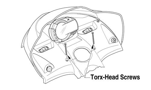
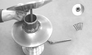
CHANGING CAM ARMS/SPRINGS (2000) Removing 1.Using Drive Clutch Bolt Tool, remove the torx-head screw and lock washer securing the drive clutch to the crankshaft.
NOTE: Before installing the clutch puller, apply oil
to the threads of the puller and a small amount of grease to the tip of the puller.
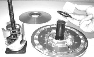
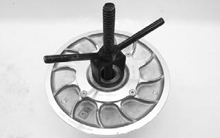
2.Using the Drive Clutch Puller and the Drive Clutch
Spanner Wrench, tighten the puller. If the drive clutch will not release, sharply strike the head of the puller. Repeat this step until the clutch releases.
3.Remove the drive clutch and drive belt from the engine compartment.
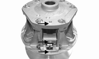
Disassembling NOTE: Note the timing marks on the cover, spider,
and movable sheave. These must be aligned when assembling the drive clutch for balance purposes.
1.Loosen the screws securing the cover. Remove every other cap screw and lock washer from the cover; then while firmly holding the cover, remove the three remaining screws and lock washers equally. 2.Remove the cover and spring.
FC055
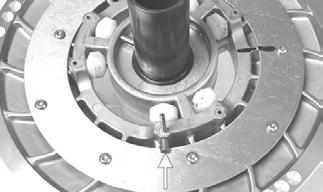
3.Remove the cam arm pin lock nuts; then using a small torch, apply heat to the cam arm set screws to loosen the Loctite used in assembly.

FS001
NOTE: Heat must be applied to the cam arm in
order to remove the set screws.
4.After the set screws have been removed, remove the cam arm pins one at a time noting the position of the alignment notches in the cap screws for assembly purposes. Account for both O-rings.
0739-038
Cleaning And Inspecting 1.Using parts-cleaning solvent, wash grease, dirt, and foreign matter off all components; dry with compressed air.
2.Remove any drive belt dust accumulation from the stationary sheave, movable sheave, and bushings using parts-cleaning solvent only. 3.Inspect stationary sheave, movable sheave, spider, and cover for cracks or imperfections in the casting. 4.Inspect the cam arm pins for wear or bends. 5.Inspect the spring for distortion, cracks, or wear. 6.Inspect rollers for damage or wear.
Assembling 1.With the head of each cam arm pin positioned towards the direction of the drive clutch rotation, install the cam arms.
! WARNING
Always wear safety glasses when using compressed air to dry components.
NOTE: The drive clutch rotates counterclockwise.
2.With the cam arm pin properly positioned, apply green Loctite #620 to the set screw holes in the cam arm, install the new set screws (pre-coated with Loctite), and tighten to 19 in.-lb.
739-040B
CAUTION
Green Loctite #620 must be applied to the set screw holes in the cam arms or component damage may occur.
3.Secure the cam arm pins with new lock nuts and tighten to 11 ft-lb.
4.Place the spring and cover into position making sure the timing mark on the cover is properly aligned; then compress the spring and install the screws coated with blue Loctite #243 and lock washers. In a crisscross pattern, tighten evenly to 120 in.-lb.
CAUTION
When installing cam arms, always use new lock nuts and cam arm set screws.
XM009A
CAUTION
Care must be taken when installing the cover not to damage the bushing.
Installing NOTE: Before installing the drive clutch, be sure to
wipe both the crankshaft taper and clutch mounting taper clean using a clean towel.
1.Place the drive clutch into position on the crankshaft. 2.Using Drive Clutch Spanner Wrench to hold the drive clutch, secure using the cap screw and high collar washer. Tighten to 51 ft-lb.
3.Check alignment between the drive clutch and driven clutch.
4.Install the drive belt. Check drive belt deflection.
Close the left-side access panel.
5.Start the engine and let the engine idle for 1-2 minutes; then shut the engine off and torque the cap screw again to 51 ft-lb.
CAUTION
When installing the drive clutch, do not tighten the cap screw with any kind of impact tool. Tighten cap screw using a hand torque wrench only. Failure to do so could result in stationary sheave damage.
! WARNING
Never operate the engine without the belt guard/access panel secured.
CHANGING CAM ARMS/SPRINGS (7000) Removing 1.Using Drive Clutch Bolt Tool, remove the torx-head screw and lock washer securing the drive clutch to the crankshaft.
NOTE: Before installing the clutch puller, apply oil
to the threads of the puller and a small amount of grease to the tip of the puller.
2.Using the Drive Clutch Puller and the Drive Clutch
Spanner Wrench, tighten the puller. If the drive clutch will not release, sharply strike the head of the puller. Repeat this step until the clutch releases.
Disassembling NOTE: Note the timing marks on the cover, spider,
and movable sheave. These must be aligned when assembling the drive clutch for balance purposes.
1.Loosen the screws securing the cover. Remove every other cap screw from the cover; then while firmly holding the cover, remove the three remaining screws equally. 2.Remove the cover and spring.
SNO-545
3.Remove the shoulder screw, washer, and lock nut securing the cam arm. Account for two thrust washers.

SNO-546
Cleaning And Inspecting 1.Using parts-cleaning solvent, wash grease, dirt, and foreign matter off all components; dry with compressed air.
2.Remove any drive belt dust accumulation from the stationary sheave, movable sheave, and bushings using parts-cleaning solvent only. 3.Inspect stationary sheave, movable sheave, spider, and cover for cracks or imperfections in the casting. 4.Inspect the shoulder screws for wear or bends. 5.Inspect the spring for distortion, cracks, or wear. 6.Inspect rollers for damage or wear.
! WARNING
Always wear safety glasses when using compressed air to dry components.
Assembling NOTE: The drive clutch rotates counterclockwise
and the shoulder screw should be installed in the direction of rotation.
1.With the cam arm pin properly positioned between the clutch tower, position the two thrust washers on each side of the cam arm with the straight edges against the bottom and outside of the clutch.
SNO-546A
2.Install washer onto the shoulder screw and install in through the clutch, thrust washers, and the cam arm.
Secure using new lock nut. Tighten to 50 in.-lb. 3.Place the spring and cover into position making sure the timing mark (X) on the cover is properly aligned with the spider and the movable sheave; then compress the spring and install the screws. In a crisscross pattern, tighten evenly to 120 in.-lb.

SNO-545
CAUTION
Care must be taken when installing the cover not to damage the bushing.
Installing NOTE: Before installing the drive clutch, be sure to
wipe both the crankshaft taper and clutch mounting taper clean using a clean towel.
1.Place the drive clutch into position on the crankshaft; then apply a few drops of oil to the threads of the cap screw.
2.Using Drive Clutch Spanner Wrench to hold the drive clutch, secure using the cap screw and high collar washer. Tighten to 51 ft-lb.
When installing the drive clutch, do not tighten the cap screw with any kind of impact tool. Tighten cap screw using a hand torque wrench only. Failure to do so could result in stationary sheave damage.
3.Check alignment between the drive clutch and driven clutch.
4.Install the drive belt. Check drive belt deflection.
Close the left-side access panel.
5.Start the engine and let the engine idle for 1-2 minutes; then shut the engine off and torque the cap screw again to 51 ft-lb.
! WARNING
Never operate the engine without the belt guard/access panel secured.
Driven Clutch
REMOVING (2000) 1.Remove the drive belt.
2.Using a 9/16-in. socket and extension, remove the cap screw securing the driven clutch to the input shaft.
3.Slide the driven clutch off the shaft.

NOTE: Account for and remove any alignment
washers. These washers must be used during installing.
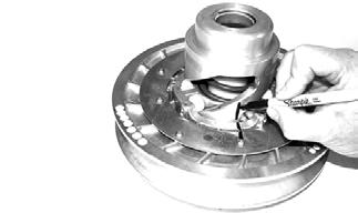
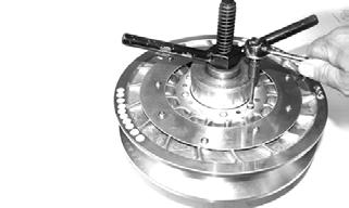
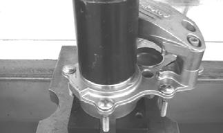
DISASSEMBLING 1.Prior to disassembling, mark the driven clutch sheaves and torque bracket.
CM060
2. Place the driven clutch on the Driven Clutch Compressor Tool; then install the compressor flange spacer and wing nut and compress the driven clutch spring. 3. Remove the torx-head cap screws securing the movable sheave to the torque bracket.
CM061
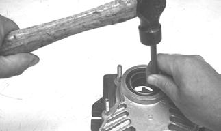
NOTE: To loosen the torx-head cap screws, it may
be necessary to insert a torx-bit and strike each screw with a hammer.
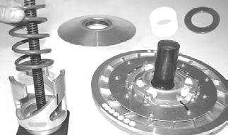
4.Release the compression of the spring by removing the wing nut; then remove the movable sheave.
Account for the torque bracket retainer. 5.Remove the stationary sheave; then remove the plastic washer (spring seat) and the spacer.
CM062
6.Remove the spring and remaining spring seats.
CM063
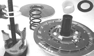
CM064
CLEANING AND INSPECTING 1.Using parts-cleaning solvent, wash grease, drive belt dust, and foreign matter off all components.
2.Inspect the rollers for damage, cracks, or wear. 3.Inspect the sheaves for any gouges, cracks, or other damage. Also, inspect threaded areas of sheaves for damaged or stripped threads. 4.Inspect the torque bracket for cracks or damage. The ramp portions of the bracket must be free of gouges and damage. Minor scratches may be repaired using #320 grit wet-or-dry sandpaper. 5.Inspect spring for distortion, crystallization, or breaks.
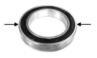
6.Inspect the rollers, pins, and spring mounting holes for cracks, damage, or wear. 7.Inspect the cover and movable sheave bearings for wear. For each respective bearing, measure the outside diameter of the shaft and the inside diameter of the bearing. Compare the readings. Clearance between the shaft and the respective bearing must not exceed 0.020in. If the clearance exceeds the specification, the driven clutch must be replaced.
CAUTION
Do not use steel wool or a wire brush to clean driven clutch components. A wire brush or steel wool will cause the sheaves to be gouged (thus, the drive belt may not slide properly between sheaves). Decreased performance and possible accelerated drive belt wear will result.
NOTE: The movable sheave bearing is a non-ser-
viceable component.


FS123
REPLACING TORQUE BRACKET BEARING/COVER BEARING 1.Remove the snap ring. 2.Using a suitable driving tool, drive the bearing out.
3.Install the new bearing; then secure with the snap ring. ! WARNING
Always wear safety glasses when using the bearing driver.
REPLACING ROLLERS 1.Drive the spring pins through the stationary sheave until the cam roller pin can be driven out.
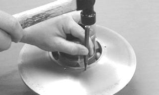
FS101
2.Using Roller Pin Remove Tool or a suitable substitute and a flat-blade screwdriver, press the roller pin out of the stationary sheave.
CM065
Care must be taken not to damage the driven clutch shaft.
NOTE: Once the roller pin is exposed, it may be
necessary to use a pair of vise-grips to remove the pin.
3.Place the new roller into position and tap the roller pin in far enough to install the spring pin.
CM067A
4.Tap the spring pin back into place.

CM068A
ASSEMBLING 1.Place the torque bracket onto the Driven Clutch
Compressor Tool; then install the spring seats onto the torque bracket and place the spring into position.
CM064 CM063
NOTE: Premature wear will result if the plastic
washer is not installed.
2.Noting the alignment marks made during disassembling and with the spring seat and spacer on the stationary sheave shaft, place the stationary sheave onto the torque bracket.
CM062
3.Place the spacer (retainer) into position on the stationary sheave with the holes properly aligned.

FS094
4.Noting the alignment marks made during disassembling, place the movable sheave onto the stationary sheave.
FS093
5.With the clutch in place on the compressor, install the compressor flange spacer and wing nut; then compress the driven clutch spring.

CM069
6.Install the torx-head cap screws securing the movable sheave. Tighten in a crisscross pattern to 72 in.-lb.
CM061
7.Remove the clutch from the compressor.
INSTALLING 1.Set the brake lever lock.
2.Install the alignment washers; then install the driven clutch onto the input shaft. Tighten to 32 ft-lb.
3.Check drive clutch/driven clutch alignment; then install the drive belt (see Drive Belt in this section).
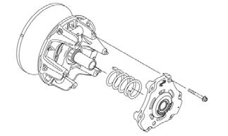
REMOVING (7000) 1.Remove the left-side access panel; then remove the cap screw and washer securing the stationary sheave to the driven shaft.
CAUTION
Do not allow the driven clutch to “float” on the input shaft. Damage to the driven clutch will occur.
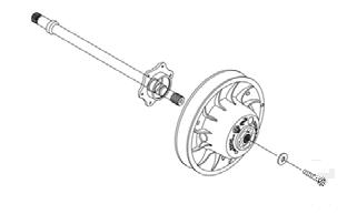
SNO-544
2.Slide the stationary sheave off the driven shaft and account for the drive belt and offset shims.

SNO-547
3.Slide the movable sheave off the driven shaft.
DISASSEMBLING 1. Place the movable sheave on the Driven Clutch
Compressor Tool with the torque bracket facing up; then install the compressor flange and handle against the torque bracket.
2. Apply heat to the screws securing the torque bracket to the movable sheave; then remove the screws.
CAUTION
Do not allow the compressor tool to touch either of the driven clutch bushings as it may cause damage.
3.Release the compression of the spring by removing the wing nut; then remove the torque bracket, spider assembly, and the driven clutch spring.


XM344
CLEANING AND INSPECTING 1.Using parts-cleaning solvent, wash grease, drive belt dust, and foreign matter off all components.
2.Inspect the rollers and spider for damage, cracks, or wear.
3.Inspect the sheaves for any gouges, cracks, or other damage. Also, inspect threaded areas of sheaves for damaged or stripped threads. 4.Inspect the torque bracket for cracks or damage. The ramp portions of the bracket must be free of gouges and damage. 5.Inspect spring for distortion, crystallization, or breaks.
6.Inspect the torque bracket and movable sheave bearings for wear. If wear is present, replace the bracket or sheave. CAUTION
Do not use steel wool or a wire brush to clean driven clutch components. A wire brush or steel wool will cause the sheaves to be gouged (thus, the drive belt may not slide properly between sheaves). Decreased performance and possible accelerated drive belt wear will result.

REPLACING ROLLERS 1.With the torque bracket removed from the movable sheave, remove the driven spider assembly from the torque bracket. 2.Remove the retaining rings and thrust washers securing the rollers on the spider.
SNO-583
3.Place a new roller into position and secure with the existing thrust washers and retaining rings making sure the rounded side of the bore is installed toward the inside or the retaining ring will not seat into the groove of the spider shaft.
ASSEMBLING 1.Place the movable sheave onto the Driven Clutch
Compressor Tool; then install the spring into the sheave making sure the tab is placed.
XM384
2.Install the spider assembly over the spring; then position the torque bracket over the spider and install the compressor flange spacer and wing nut; then compress the torque bracket until the mounting locations align.
XM344
3.Install new Screws securing the torque bracket.
Tighten in a crisscross pattern to 120 in.-lb.
XM347
5.Remove the clutch from the compressor.
INSTALLING (7000) 1.Set the brake lever lock.
2.Install the movable sheave onto the driven shaft until it is fully seated onto the splines of the shaft; then install the offset shims and the stationary sheave.
SNO-547
3.Secure the sheaves using the existing cap screw and washer making sure the washer is cupped toward the sheave. Tighten to 60 ft-lb; then install the drive belt.

SNO-544
4.Check drive clutch/driven clutch alignment.
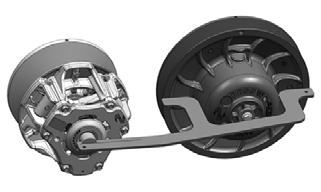
Drive Clutch/Driven Clutch
If premature drive belt wear is experienced or if drive belt turns over, check parallelism/offset. Also, parallelism/offset must be checked whenever either drive clutch or driven clutch is serviced. To check offset, use appropriate Clutch Alignment Bar. To check parallelism, use Parallelism Bar.
CHECKING OFFSET (2000) 1.With the engine off, open the left-side access panel; then remove the drive belt.
2.Install appropriate Clutch Alignment Bar between the drive clutch sheaves.
3.Allow the bar to rest on the drive clutch shaft and against the outside edge of the driven clutch stationary sheave. NOTE: The alignment bar must extend beyond the
front edge of the drive clutch.
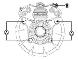
4.With the bar against the outside edge of the driven clutch stationary sheave at points A and B, the bar should just clear the inside edge of the stationary sheave of the drive clutch and rest on the stationary shaft at point C. If the bar either will not clear the inside edge or is more than the specified amount, the offset must be corrected.
0747-959
CORRECTING OFFSET (2000) 1.To correct offset, the driven clutch must be moved laterally on the input shaft. Remove the cap screw and washers securing the driven clutch. NOTE: If the driven clutch is tight on the shaft, pull
the driven clutch off using the Driven Clutch Puller.
2.To move the driven clutch inward on the shaft, remove alignment washers located on driven shaft from the chain case of the clutch.
3.To move the driven clutch outward on the shaft, add alignment washers to the driven shaft on the chain case of the clutch.
4.Arrange washers to obtain correct offset; then install driven clutch, cap screw, and washers. 5.Install the drive belt.
CHECKING OFFSET (7000) NOTE: The drive belt does not need to be removed
to check offset.
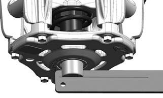
1.Set the brake lever lock; then remove the left-side access panel. 2.Place Alignment Plug into the bore of the drive clutch; then place Alignment Bar onto the stationary sheave of the driven clutch and into the groove of the alignment plug.
SNO-578
NOTE: Make sure the alignment bar is positioned
over the driven clutch cap screw.
3.If the offset is correct, the line on the alignment bar will be aligned with the outside of the alignment plug. If not, proceed to Adjusting Offset.
SNO-579
NOTE: To achieve proper offset, the driven clutch
cap screw and washer must to be installed and tightened to 60 ft-lb.
CORRECTING OFFSET (7000) 1.Thread Belt Removal/Installation Tool clockwise into the driven clutch until the movable sheave opens far enough to remove the drive belt. Remove the belt and the tool.
0749-025
2.Remove the cap screw and washer securing the driven clutch to the driven shaft; then remove the stationary sheave from the shaft. 3.To move the stationary sheave inward on the shaft, remove alignment washers located on driven shaft. 4.To move the stationary sheave outward on the shaft, add alignment washers to the driven shaft. NOTE: Available shim washers from Arctic Cat are
p/n 0648-850 (0.090 in.) and (p/n 0648-849 (0.030 in.). When adding or removing washers, the thickest washer in the stack needs to be the most inward on the shaft.
5.Arrange washers to obtain the correct offset; then install stationary sheave and secure using the cap screw and washer. Tighten to 60 ft-lb. 6.Install the drive belt.
DRIVE BELT DEFLECTION (2000) Drive belt length, condition, and deflection are all important for peak performance. To check and adjust drive belt deflection, use the following procedure. NOTE: Make sure the drive belt is sitting at the top
of the driven clutch sheaves.
1.Place a straightedge on top of the drive belt. The straightedge should reach from the drive clutch to the top of the driven clutch. 2.Using a stiff ruler centered between the drive clutch and driven clutch, push down on the drive belt just enough to remove all slack. Note the amount of deflection on the ruler at the bottom of the straightedge. The deflection should be approximately28.5-31.8 mm (1 1/8-1 1/4 in.).

0743-319
NOTE: Push down on the belt with the ruler only
until the bottom of the belt flexes upward; then read the amount of deflection.
3.To correct drive belt deflection, remove the sheave adjuster from the clutch, remove or add shim washers to the adjuster, and install the adjuster. NOTE: After any adjustment have been made,
make sure the drive belt is sitting at the top of the driven sheaves. Support the rear suspension up in the air; then run the sled for a few seconds and let the track slow down to a stop. Turn the engine off and check deflection again. Adjust as necessary.
NOTE: Adding shim washers will decrease belt
deflection; removing shim washers will increase belt deflection.
CHECKING/ADJUSTING DEFLECTION (7000) Drive belt length, condition, and deflection are all important for peak performance. To check and adjust drive belt deflection, use the following procedure. 1.With the engine off; remove the hood and left-side access panel. 2.Make sure the drive belt is sitting at the top of the driven clutch sheaves.
3.Place a straightedge on the top of the drive belt. The straightedge should reach from the drive clutch to the top of the driven clutch. 4.Using a stiff ruler centered between the drive clutch and driven clutch, push down on the drive belt just enough to remove all slack and note the amount of deflection. The deflection should be approximately 28.5-31.8 mm (1 1/8-1 1/4 in.).

0748-987
NOTE: The amount of deflection should be experi-
mented with or tested to obtain best start-line performance.
NOTE: Push down on the belt with the ruler only
until the bottom of the belt flexes upward; then read the amount of deflection.
5.To correct drive belt deflection, loosen the jam nut on the belt width adjuster on the stationary sheave. NOTE: Make sure the jam nut and set screw is
located on the opposite side from the drive clutch when checking or adjusting the deflection.
SNO-597A
6.Using an Allen wrench, adjust the set screw as needed.
NOTE: Turning the set screw clockwise increases
distance between the sheaves (increases belt deflection measurement); turning the set screw counterclockwise decreases distance between the sheaves (decreases belt deflection measurement).
Removing Gear Case/Track Driveshaft........................130 Installing Track Drive shaft/Gear Case........................131 Disassembling Gear Case.............................................133 Cleaning and Inspecting Gear Case.............................135 Assembling Gear Case..................................................135 Flushing Gear Case.......................................................137
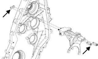
2000 REMOVING GEAR CASE/TRACK DRIVESHAFT NOTE: The gear case drive fluid does not have to be
drained for this procedure.
1.Remove the access panels from both sides of the snowmobile.
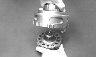
2.Engage the brake lever lock; then remove the cap screw securing the driven clutch to the input shaft.
Remove the clutch from the shaft.
NOTE: After removing the driven clutch, account
for any alignment washers (if applicable). These washers must be used during installing.
3.On the Lynx models, remove the torx-head cap screws securing the toe shield and hook bracket to the chassis and remove the shield and bracket.
0742-089
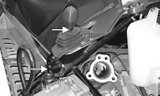
4.Loosen the cap screw (from the brake disc side of the inner drive shaft) securing the drive shaft to the gear case. NOTE: If the gear case is being removed, do not
remove the 5/8-in. cap screw. If only the track drive shaft is being removed, remove the cap screw and proceed to step 10.
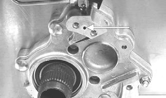
5.Remove the lock nuts securing the gear case to the chassis; then remove the remaining lock nut (A) from the torx-head cap screw.


742-195E
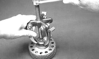
6.Place the snowmobile in the upright position; then using a 5/8-in. socket, long extension, and a hammer, tap against the drive shaft cap screw until the gear case is free from the studs of the mounting plate. 7.Remove the cap screw from the inner drive shaft (from step 4); then remove the gear case. NOTE: If the gear case is difficult to remove, it may
be necessary to loosen the track tension.
NOTE: Account for the torque bumper. 8.Remove the hairpin clip and springs securing the resonator; then remove the resonator from the engine compartment. NOTE: Remove the negative cable from the battery;
then remove the positive cable. Remove the hardware securing the battery to the tray; then remove the battery.
9.Remove the two cap screws securing the speedometer sensor bracket. Account for two spacers.

ZJ210A
10.Lock the brake lever; then using Brake Disc Socket
Wrench, remove the retaining nut from the drive shaft.
12.On the Lynx models, remove the rear cap screws securing the skid frame to the tunnel; then slide the skid frame rearward far enough to drop the front arm out of the slider axle and remove the skid frame.
Account for lock washers and flat washers.
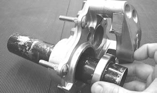
13.On the Bearcat, remove all four cap screws and lock nuts (if applicable); then remove the skid frame. 14.With the gear case and skid frame removed, pull the drive shaft toward the gear case side of the tunnel until it clears the brake caliper housing; then remove the drive shaft. Account for the rubber seal.
! WARNING
Care must be taken when removing the spring or damage or injury could result.

ZJ212
NOTE: The brake disc can remain locked in the
brake caliper unless being serviced.
NOTE: At this point if necessary, remove the track.
INSTALLING TRACK DRIVESHAFT/GEAR CASE NOTE: At this point if the track was removed,
install the track.
NOTE: Steps 1-8 are for installing the track drive-
shaft. If only installing the gear case, proceed to step 9.
NOTE: Prior to installing the driveshaft, apply a
coat of Anti-Seize Thread Compound to the internal splines of the driveshaft.
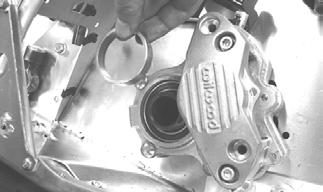
1.If the brake disc was removed, place the track/driveshaft assembly into the bearing of the brake housing just far enough to allow the brake disc to be installed in the brake housing assembly.
ZJ214A
NOTE: Prior to installing the driveshaft, ensure the
driveshaft sleeves are centered to the inner bore of the brake caliper housing.
ZJ307A
2.With the brake lever lock engaged and the brake disc correctly positioned in the brake housing assembly, properly align the splines of the driveshaft with the brake disc; then push the driveshaft the rest of the way into the brake housing until properly seated.

ZJ215A
3.Apply Anti-Seize Thread Compound to the threads of the brake disc retaining nut; then install the nut. 4.With the brake lever in the locked position, use
Brake Disc Socket Wrench to tighten the brake disc retaining nut to 120 ft-lb.

ZJ237
NOTE: After the retaining nut is tightened to specifi-
cations, peen the nut at the flat spot of the driveshaft.
5.Install the speedometer sensor mounting bracket (with two spacers); then secure with the two cap screws. Tighten to 17 ft-lb. NOTE: At this point, install and secure the battery;
then connect the battery cables (positive cable first).
6.If the gear case is installed, secure the driveshaft to the output shaft with the cap screw (coated with blue
Loctite #243) and washer. Tighten to 70 ft-lb.
742-020A

NOTE: If the gear case is not installed, do not secure
the driveshaft to the output shaft at this time. Proceed to step 7.
7.Place the resonator into position and secure with the springs and hairpin clip. 8.Install the skid frame.
NOTE: At this point if the gear case is installed, pro-
ceed to step 22 to finish installing the track drive shaft.
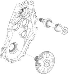
9.Place the gear case onto the drive shaft; then press the gear case toward the sprocket until it properly seats into place on the chassis. It may be necessary to rotate the drive shaft slightly for proper seating. NOTE: Prior to placing the gear case onto the drive
shaft, apply a light coat of Anti-Seize Thread Compound to the splines of the drive shaft.
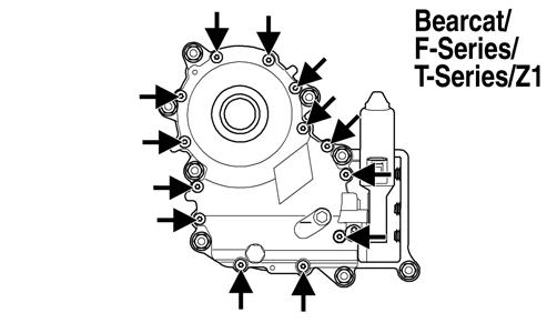
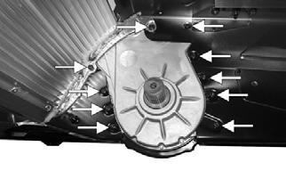
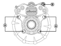
10.Secure the gear case by installing the lock nuts; then using the pattern shown, evenly tighten all the nuts to 20 ft-lb.
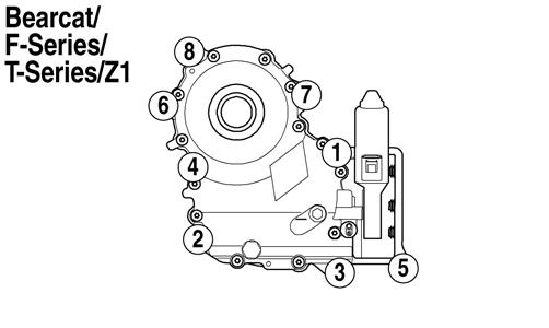
742-195B
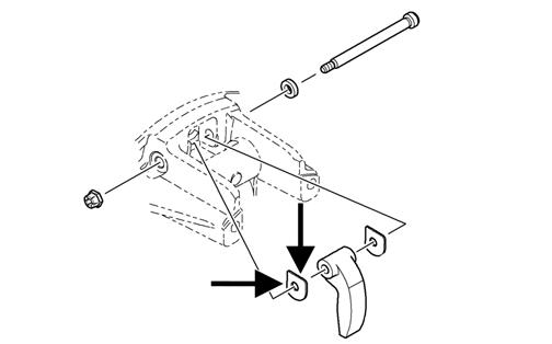
11.Install the torque bumper behind the engine mounting bracket; then carefully work it into place with the aid of a flat-blade screwdriver.
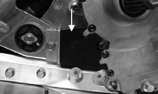
ZJ309B
NOTE: Use of a quality silicone spray will aid in
installing the torque bumper.
12.Install the toe shield and toe hook bracket; then install the torx-head cap screws. Tighten securely.
0742-089
13.Install the cap screw (coated with blue Loctite #243) securing the drive shaft to the gear case; then tighten to 70 ft-lb.
0742-020
14.Slide the driven clutch onto the input shaft making sure alignment washers are in place (if applicable). 15.Secure the driven clutch with components and hardware as noted in removing. Tighten to 32 ft-lb.
16.Install the drive belt.
17. Check the track for alignment and recommended tension; then tighten the cap screws securely. 18.Install and secure the access side panels.
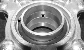
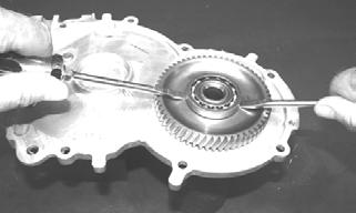
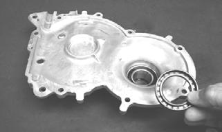
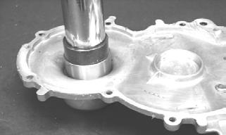
DISASSEMBLING GEAR CASE 1.Remove the torx-head cap screws securing the gear case cover to the gear case assembly; then insert two flat-blade screwdrivers into the slots on the gear case. Working back and forth, pry the cover up and off the gear case. Discard the gasket.

742-195C
2.Drain the gear case fluid into a suitable container.

3.Secure the gear case cover in a suitable clamping device; then using two flat-blade screwdrivers from opposite sides of the cover bearing, evenly pry the input shaft bearing up and off the shaft.
CAUTION
If the input shaft bearing is removed, always replace it with a new one or severe component damage may occur.
ZJ189
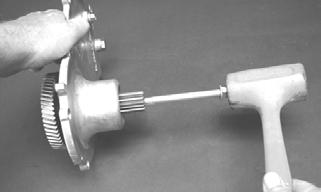
4.With a cap screw threaded into the input shaft and using a soft hammer, drive the input shaft out of the gear case cover.
ZJ190
5.Using a suitable bearing press and fixture, press the input shaft bearing out of the gear case cover.
Account for a bearing and a seal.
ZJ191
MS331
6.Secure the gear case in a suitable clamping device; then using the procedure from step 5, remove the outer bearing from the transfer gear.

ZJ192
CAUTION
If any transfer gear bearings are removed, always replace them with new ones or severe component damage may occur.
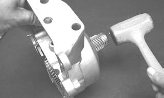
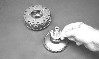
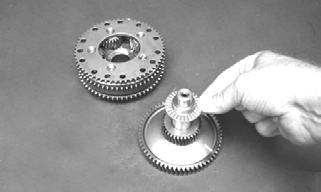
7.Place the gear case on its side; then using a soft hammer, tap the output shaft until the slider and output gear assembly come free of the gear case.
ZJ193
8.Remove the output gear assembly from the slider housing.
ZJ194
9.Using a suitable bearing puller, remove the inner bearing from the transfer gear assembly. Account for a spacer washer.
ZJ195
10.Remove the transfer gear from the planetary gear assembly and account for the thrust washer and thrust bearing.
ZJ196
NOTE: For assembling purposes, note that the
thrust bearing is positioned between the thrust washer and the gear assembly.
ZJ197
11.Remove the retaining ring and thrust washer securing the slider housing assembly to the output shaft assembly.
ZJ200
12.Using a suitable puller, remove the bearing from the output shaft. 13.Using a suitable seal removing tool, remove the output/input shaft seals from the gear case.

ZJ204
CLEANING AND INSPECTING GEAR CASE NOTE: The planetary gear assembly is a non-ser-
viceable component. If any damage or wear is detected, it must be replaced.
1.Wash the gear case halves and unsealed bearing in parts-cleaning solvent. 2.Inspect the gear case halves for trueness, scoring, pitting, scuffing, or any imperfections in the casting. 3.Inspect all threaded areas for damaged or stripped threads.
4.Inspect the bearing areas for cracks or excessive bearing movement. If evidence of excessive bearing movement is noted, replace the component. 5.Inspect the gears for wear, cracks, or chipped teeth. 6.Inspect the input shaft/transfer gear bearings for wear, scoring, scuffing, damage, or discoloration.
Rotate the bearings. Bearings must rotate freely and must not bind or feel rough. If any abnormal condition is noted, replace the bearing. NOTE: The output shaft bearing is a non-service-
able component. If any damage or binding is noted, the output shaft assembly must be replaced.
7.Apply a light film of Arctic Cat Synthetic ACT
Drive Fluid to the unsealed bearings prior to assembling.
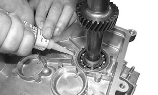
ASSEMBLING GEAR CASE 1.With the narrow, raised edges of the seal (A) facing outward and using an appropriate seal installation tool, install the oil seal into the output shaft opening of the gear case. NOTE: Grease must be applied to the seal prior to
installing.
ZJ303A

ZJ304
NOTE: Always install the seal with the wide, raised
edge of the seal facing against the seal surface of the gear case.

ZJ305A
2.Place the output shaft assembly into position in the slider housing; then secure the assembly to the housing with the thrust washer and retaining ring.

ZJ200
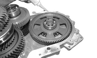
3.Using a suitable bearing press, install the bearing onto the ring gear.
ZJ199
4.In order, install the thrust washer and then the thrust bearing onto the transfer gear shaft.
ZJ208
6.Install the output gear assembly into the slider assembly until the inner bearing is properly seated.
ZJ194
7.With the alignment notches of the slider and gear case properly positioned, install the slider/output gear assembly into the gear case.

ZJ196
ZJ197
5.Position the planetary gear assembly onto the transfer gear shaft; then install the spacer washer. Using a suitable press, install the inner bearing onto the transfer gear shaft.
ZJ201
8.Using a suitable bearing press, install the outer bearing onto the transfer gear shaft.
ZJ199
9.Using a suitable bearing press and fixture, install the input shaft bearing to the gear case; then install the oil seal.
NOTE: A light coat of grease must be applied to the
seal prior to installing.
ZJ202
ZJ204
10.Using a suitable press, install the input shaft to the gear case cover.
MS349
11.With the dowel pins and new gasket in place, install the cover to the gear case and secure with the torx-head cap screws; then in a crisscross pattern, tighten to 100 in.-lb.
742-195D
12.Pour 12 fl oz of Arctic Cat Synthetic ACT Drive
Fluid into the drain/fill hole; then install the plug.
Tighten to 12 ft-lb.
CAUTION
Do not add more or less than the recommended amount of drive fluid to the gear case or damage to the gear case will occur.
FLUSHING GEAR CASE 1.Remove the access panels; then remove the belt guard. 2.Remove the drive belt (see Drive Belt in this section); then remove the driven clutch. 3.Tip the snowmobile onto its right side and use a suitable support to protect the snowmobile from the floor.
4.Remove the drain plug from the gear case; then install a drain adapter fitting with hose into the drain plug hole.

741-636A
NOTE: To aid in draining the lubricant, it is advis-
able to fashion a drain adapter by using the Gear Case Drain Fitting and a length of 3/8-in. hose.
5.Tip the snowmobile back to the upright position; then place a drain pan on the floor next to the drain hose and tip the snowmobile toward its left side far enough to allow the lubricant to drain from the gear case into the drain pan. NOTE: It is critical that the snowmobile is on a level
surface to ensure the lubricant drains properly and completely.
7.When the lubricant has completely drained from the gear case, tip the snowmobile back to the upright position, remove the drain adapter, and install and securely tighten the drain plug; then remove the check/fill plug. 8.Pour the recommended amount of Arctic Cat ACT
Drive Flush Fluid into the check/fill hole; then install the plug. Tighten securely.
9.Install the driven clutch and tighten to 32 ft-lb; then install the drive belt (see Drive Belt sub-section) and the belt guard. 10.Install the access panels. 11.Using a shielded safety stand, raise the rear of the snowmobile off the floor making sure the track is free to rotate.
12.Start the engine and accelerate slightly. Use only enough throttle to turn the track several revolutions.
SHUT ENGINE OFF.
13.Remove the access panels; then remove the belt guard. 14.Remove the drive belt (see Drive Belt sub-section); then remove the driven clutch.
15.With the stand in place, tip the snowmobile onto its right side. 16.Remove the drain plug from the gear case; then install the drain adapter fitting with hose into the drain plug hole. 17.Tip the snowmobile back to the upright position; then place a drain pan on the floor next to the drain hose and with the stand in place, tip the snowmobile toward its left side far enough to allow the flush fluid to drain from the gear case into the drain pan. 18.Secure the snowmobile in this position until the flush fluid is completely drained. 19.When the fluid has completely drained from the gear case, tip the snowmobile back to the upright position, remove the drain adapter, and install and tighten the drain plug to 12 ft-lb; then remove the check/fill plug.
20.Pour the exact amount (see appropriate specification sheet) of Arctic Cat Synthetic ACT Gear Case Fluid into the check/fill hole; then install the plug. Tighten to 12 ft-lb.
21.Install the driven clutch and tighten to 32 ft-lb; then install the drive belt (see Drive Belt sub-section) and the belt guard. 22.Install and close the access panels.
CAUTION
All old lubricant must be drained from the gear case prior to flushing the gear case.
CAUTION
Do not add more or less than the recommended amount of flush fluid to the gear case.
! WARNING
DO NOT stand behind the snowmobile or near the rotating track. NEVER run the track at high speed when the track is suspended.
CAUTION
All flush fluid must be drained from the gear case prior to filling with new lubricant.
CAUTION
The correct lubricant to use in the gear case is Arctic Cat Synthetic ACT Gear Case Fluid. Any substitute may cause serious damage to the drive system.
CAUTION
Do not add more or less than the recommended amount of lubricant to the gear case or damage to the gear case will occur. Oil level should be at the Oil Fill Level on the gear case cover.
7000 REMOVING TRANSMISSION 1.Open the hood and remove both access panels. 2.Remove the cap screws, washers, and nut securing the upper exhaust manifold heat shield.
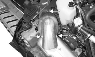
BC246A
3.Remove the cap screws and nuts securing the resonator to the exhaust manifold. Discard the gasket.
Remove the resonator.

4.Remove the two nuts and one cap screw securing the resonator mounting bracket to the transmission and the chassis. Remove the bracket.

BC314
5.Remove the retaining pin securing the shift knob to the shift lever. Remove the knob.
6.Remove the two screws securing the shift lever to the shift lever assembly. Remove the lever.
BC315A
7.Remove the screws securing the right- and left-side footrest to the chassis; then remove the self-tapping screws securing the upper rear portions of the skid plates to the footrest support. 8.Using a long extension and a 13 mm socket, remove the cap screw securing the driveshaft to the transmission.
0749-696
9.Remove the retaining pins securing the brake pads.
Remove both pads; then remove the three cap screws securing the brake caliper to the tunnel.

BC304
10.Remove the retaining ring securing the brake disc; then remove the cap screws securing the skid frame.
Remove the skid frame.
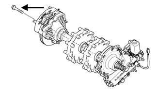
11.Remove the driveshaft assembly; then remove and discard both clamps securing the transmission input shaft into the driven shaft.

BC303A
12.Remove the screws securing the transmission to the chassis noting the two upper shorter screws. Carefully remove the transmission.
BC302A
DISASSEMBLING TRANSMISSION NOTE: Do not disassemble any of the gear assem-
blies or the shift rod assembly. They are non-serviceable components and are only sold as assemblies.
NOTE: Make sure the transmission is shifted into
neutral before disassembling.
1.Remove the four screws securing the shift lever assembly to the transmission cover; then remove the lever assembly.
SNO-635
2.With the transmission supported on blocks so the input and output shafts are not touching the bench, remove the cap screws securing the transmission cover. Remove the cover and account for two dowel pins.

SNO-633
3.Remove both magnets from the end of the shift rod assembly; then remove the two nuts securing the shift rod assembly to the inside case assembly.
SNO-634
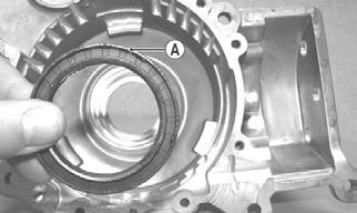
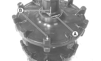
4.Remove the super low/reverse transfer gear (A), high/low transfer gear (B), and the shift rod (D) as an assembly from the inside case.

SNO-632A
5.Remove the transfer idler gear (C), input shaft (E), and the output shaft (F) from the inside case. 6.Inspect the input and output seals and replace as necessary. 7.Inspect and clean all components. Replace as necessary. 8.Clean all sealing surfaces free of any sealant.
ASSEMBLING TRANSMISSION NOTE: All sealing surfaces should be clean and dry. NOTE: Make sure the transmission is shifted into
neutral before assembling.
1.Grease the lips of the input and output seals; then install the input and output shafts into the case making sure they are fully seated.
SNO-636
2.Apply an even, continuous 1/8-in. bead of silicone to the surface around the two mounting holes for the shift rod.
BC308
3.Install the transfer idler gear into the case making sure it is fully seated; then with the shift rod assembly positioned in the super low/reverse transfer gear and the high/low transfer gear, install the assembly into the case making sure the splines on the gears align with the transfer idler gear splines.

BC309
6.Remove the three screws securing the gear position sensor to the transmission cover. Account for a rubber O-ring.
SNO-637
7.With both dowel pins installed into the transmission case half, position the transmission cover onto the case half making sure the dowel pins align along with the two shafts from the shift rod.
8.Secure the cover to the case half using the existing cap screws. Tighten to 20 ft-lb using a criss-cross pattern.
SNO-631
4.Secure the shift rod assembly to the inner case using the existing nuts. Tighten to 72 in.-lb. 5.Apply an even, continuous 1/8-in. bead of silicone to the sealing surface of the transmission case half.
SNO-633
9.Install the magnets onto the two shafts of the shift rod assembly making sure the flat sides of the magnets match the flat side of the shafts. Install the gear position sensor (with a greased O-ring) over the magnets and secure using the existing screws (threads coated with blue Loctite #243). Tighten to 24 in.-lb.
SNO-637
10.Apply an even, continuous 1/8-in. bead of silicone to the sealing surface of the shift lever assembly; then install the shift lever assembly making sure the groove in the lever is installed forward. Secure using the existing screws (threads coated with blue Loctite #243). Tighten to 96 in.-lb.
SNO-635
11.Once the sealant is dry, add Synthetic ACT Gearcase
Fluid (27.1 oz.) in through the fill hole.
INSTALLING TRANSMISSION 1.Loosely install new clamps onto the driven shaft boot; then install the boot over the driven shaft.
2.Position the transmission assembly into the chassis aligning it with the mounting locations and the drive shaft; then secure the transmission to the tunnel using the existing machine screws (threads coated with blue Loctite #243). The two short screws thread into the two upper mounting locations. Tighten to 10 ft-lb. CAUTION
Apply ample grease into the driven shaft boot to avoid premature wear to the splines onto the input shaft.
BC302A
3.Secure the driven shaft boot using the new clamps.
BC303A
4.With the seal installed onto the drive shaft, install the drive shaft over the output shaft on the transmission; then secure the brake caliper and brake disc over the shaft and secure using the existing three cap screws (threads coated with blue Loctite #243). Tighten to 25 ft-lb.
5.Secure the brake disc using the existing retaining ring; then install and secure the brake pads using the existing retaining pin.
CAUTION
Be sure to lightly grease the seal that is installed against the transmission. Failure to grease the lip of the seal will cause wear to the transmission case.
BC304
6.Secure the driveshaft to the output shaft on the transmission using the existing cap screw (threads coated with blue Loctite #243). Tighten to 50 ft-lb.
NOTE: A 13 mm socket and a long extension will be
required for installing the cap screw through the center of the drive shaft.
0749-696
7.Install the skid frame assembly using the existing cap screws (threads coated with blue Loctite #243).
Tighten to 45 ft-lb. 8.Install the suspension springs onto the coupling blocks.
9.Install the brake disc shield using the existing screws. Tighten the two cap screws securing the shield to the caliper to 8 ft-lb. 10.Install the right- and left-side footrest to the chassis using the existing screws. Do not over-tighten. 11.Position the right- and left-side skid plates into the tunnel riser and secure using the existing self-tapping screws. Do not over-tighten.
12.Install the two push pins from the harness into the right-side skid plate. Cable tie as necessary.
BC313
13.Position the resonator mounting bracket to the transmission and the chassis and secure using the existing two nuts and one cap screw. Tighten securely.
BC314
14.Position the shift lever up through the shift boot and align with the groove in the shift lever assembly.
Secure using the existing machine screws. Tighten securely. Install the shift knob and secure using the push pin.
BC315A
15.Install the resonator and secure to the exhaust manifold using a new exhaust gasket, existing cap screws, and existing nuts. Tighten to 12 ft-lb.
BC247A
16.Secure the upper exhaust manifold heat shield using the existing cap screws, washers, and nut. Tighten to 8 ft-lb.
BC246A
17.Install both access panels and secure using the pins.
Close and latch the hood.
Drive Sprockets
REMOVING NOTE: The drive sprockets must be removed from
the gear case end of the driveshaft.

ZJ216A
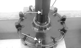
1.For installing purposes, scribe a line on the driveshaft (A) next to the drive sprocket for proper alignment; then scribe a line on the driveshaft directly in line with the timing arrows (B) on the drive sprockets for proper sprocket timing.

ZJ217
CAUTION
Always press against the tension-collar of the drive sprockets or damage to the components will occur.
ZJ218A
CLEANING AND INSPECTING 1.Thoroughly wash all metallic components in parts-cleaning solvent. Dry using compressed air. 2.Wash all non-metallic components with soap and water.
3.Inspect the driveshaft for damaged splines or stripped threads. 4.Inspect the seals for any breaks or damage. 5.Inspect the track for cuts, gouges, or wear. 6.Inspect the brake disc for wear or cracks. 7.Inspect the track drive sprockets for wear or damage.
INSTALLING NOTE: The drive sprockets must be installed on the
gear case end of the driveshaft.
MS357A
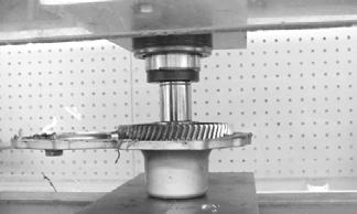
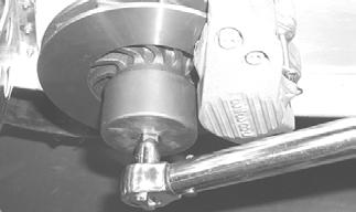
2.Using a suitable press positioned against the tension-collar of the drive sprocket (located on the gear case) and of the driveshaft, press the drive sprockets off the driveshaft.
ZJ216A
NOTE: Prior to installing the sprockets onto the
driveshaft, lightly chamfer the inside edge of the sprocket to avoid binding.

MS362
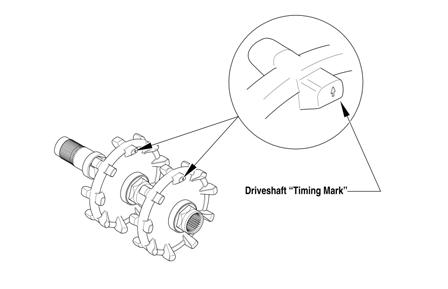
1.Properly align the scribed line on the driveshaft (from removing) with the timing arrow on the drive sprocket; then slide the sprocket onto the driveshaft as far as it will go.

MS360A
2.Using a suitable press and fixture, press the driveshaft into the sprocket until it aligns with the line scribed in removing.

MS361A
3.Slide the remaining sprocket onto the driveshaft making sure the timing arrow/lines (from removing) are aligned; then using the press/fixture, press the sprocket to the remaining alignment line.
CAUTION
Always press against the tension-collar of the drive sprockets or damage to the components will occur.

MS359A
NOTE: The drive sprockets must be installed on the
brake disc end of the driveshaft.
MS313C
NOTE: When pressing new sprockets on the drive-
shaft, align the sprocket alignment marks or the sprockets won’t be timed correctly.
740-043A
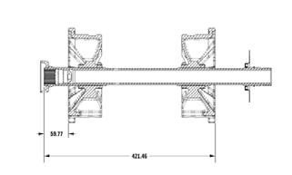
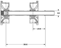
4.Using a calipers, measure distances between the sprockets and from the sprockets to each end of the driveshaft for proper location (see appropriate illustration).
MS364

Bearcat 7000/Pantera 7000 XT LTD
0749-899
Lynx/Lynx LT/Bearcat 2000 LT

0744-060 ONS-051
Track Tension
CHECKING
! WARNING
DO NOT attempt to check or adjust track tension with engine running. Turn ignition key to the OFF position. Personal injury could result from contact with a rotating track.
1.Remove excess ice and snow buildup from the track, track drive sprockets, and the inside of the skid frame.
2.Elevate the rear of the snowmobile on a shielded safety stand high enough to use a spring scale. 3.At mid-point of the track (on the bottom side), hook a spring scale around a track clip; then pull down on the scale to the recommended pressure. Measure the deflection (distance) between the bottom of the wear strip and the running surface of the track clip.
Model Pressure Setup Tension
Lynx 2000/Lynx 2000 LT/ Bearcat 2000 LT
20 lb 44-51 mm (1.75-2-in.) Bearcat 2000 XT 10 lb 44-51 mm (1.75-2-in.)
Bearcat 7000 XT/GS/ Pantera 7000 XT LTD 20 lb 44-51 mm (1.75-2-in.)
After Break-In Tension
51-57 mm (2-2.25 in.) 51-57 mm (2-2.25 in.) 51-57 mm (2-2.25 in.)
NOTE: Measurement is from the bottom of the
wear strip at the point of the shock pad on the slide rail.
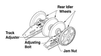
ADJUSTING 1.If the measurement is not as specified, loosen the jam nuts of the adjusting bolts.

739-636B
NOTE: On articulating rear skid frame models, the
rear axle cap screws must also be loosened.
743-323A
2.If the measurement is more than specified, tighten the adjusting bolts. If the measurement obtained is less than specified, loosen the adjusting bolts. When the measurement is within specification range, lock the adjustment by bottoming the jam nuts against the axle housings. NOTE: Vigorously push the underside of the track
up and down. Track must not hit the top of the tunnel or slap the skid frame.
3.After correct track tension is obtained, check track alignment (see Track Alignment in this section). NOTE: Track tension and track alignment are
interrelated; always check both even if only one adjustment seems necessary. Always establish correct track tension before checking and/or adjusting alignment.
CAUTION
After proper track tension has been attained, make certain that the rear axle cap screws are tightened to specifications or component damage will occur.
Track Alignment
NOTE: Proper track alignment is when the rear
idler wheels are equidistant from the inner drive lugs on the inside surface of the track.
Make sure the ignition key is in the OFF position and the track is not rotating before checking or adjusting track alignment. Personal injury could result if contact is made with a rotating track.
1.Remove excess ice and snow buildup from the track, track drive sprockets, and the inside of the skid frame.
2.Position the tips of the skis against a wall; then using a shielded safety stand, raise the rear of the snowmobile off the floor making sure the track is free to rotate.
3.Start the engine and accelerate slightly. Use only enough throttle to turn the track several revolutions.
SHUT ENGINE OFF.
! WARNING
The tips of the skis must be positioned against a wall or similar object for safety. Keep hands, feet, and clothing away from moving components.
! WARNING
DO NOT stand behind the snowmobile or near the rotating track. NEVER run the track at high speed when the track is suspended.
NOTE: Allow the track to coast to a stop. DO NOT
apply the brake because it could produce an inaccurate alignment condition.
4.When the track stops rotating, check the relationship of the rear idler wheels and the inner track drive lugs.
If the rear idler wheels are centered between the inner track drive lugs, no adjustment is necessary. If not, proceed to step 5. 5.On the side of the track which has the inner track drive lugs closer to the rear idler wheel, loosen the adjusting bolt jam nut; then rotate the adjusting bolt clockwise 1-1/2 turns.
739-636B
NOTE: On articulating rear skid frame models, the
rear axle cap screws must also be loosened.
743-323A
6.Check the track alignment and make the necessary adjustments until proper alignment is obtained. NOTE: Make sure correct track tension is main-
tained after adjusting track alignment (see Track Tension sub-section in this section).
7.After proper track tension and alignment are obtained, lock the jam nut against the axle housing. NOTE: Field test the track under actual conditions
and after the field test, check track alignment and track tension; adjust as necessary.
! WARNING
If jam nuts are not locked, the adjusting bolts could loosen causing the track to ratchet, derail, or lock.
Brake System (2000)
CHECKING BRAKE LEVER TRAVEL 1.Compress the brake lever fully. NOTE: Do not pump the brake lever as it will pro-
duce an inaccurate reading.
2.Measure the distance between the brake lever and the handlebar. The distance must be greater than 1in. 3.If the distance is less than specified, check the brake fluid level (see CHECKING AND ADDING
BRAKE FLUID in this sub-section), inspect for leakage, and check the brake pads (see CHECKING
AND REPLACING BRAKE PADS in this sub-section).
! WARNING
Do not operate the snowmobile if the distance between the compressed brake lever and handlebar is less than 1 in. Brake loss may occur. Brake loss can result in severe personal injury.
CHECKING AND ADDING BRAKE FLUID 1.On 2000 models, with brake fluid reservoir in a level position, check the fluid level. The brake fluid level must be visible in the sight glass.
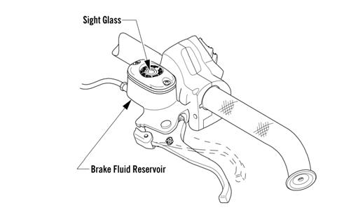
741-328D
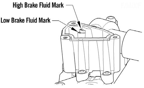
2.On 7000 models, with the brake fluid reservoir in a level position and the cover removed, check the fluid level. The brake fluid level must be at the high brake fluid mark in the reservoir.
745-817A
3.If the brake fluid level is low, add Arctic Cat approved brake fluid until the fluid is at the recommended level. Install and secure the reservoir cover.
DO NOT allow moisture to contaminate the brake system.
CAUTION
Brake fluid is highly corrosive. Do not spill brake fluid on any surface of the snowmobile.
! WARNING
Do not overfill the brake fluid reservoir. Overfilling the reservoir may cause the brake system to hydraulically lock. Use only approved brake fluid. Never substitute or mix different types or grades of brake fluid. Brake loss may occur. Brake loss can result in severe injury or even death.
CHANGING BRAKE FLUID The brake fluid must be changed on a regular basis and/or whenever the brake fluid has been overheated or contaminated. The brake fluid should be changed every 1000 miles or at the end of the snowmobiling season, whichever occurs first.
Arctic Cat recommends the removal and disassembly of the brake caliper assembly when changing the brake fluid (see BRAKE CALIPER/BRAKE DISC/DRIVESHAFT BEARING in this sub-section).
CAUTION
Use only Arctic Cat approved brake fluid. Any substitute may result in a loss of brakes.
! WARNING
Do not use brake fluid from a container opened for a long period of time. Unsealed brake fluid containers will absorb moisture and can contaminate the fluid inside.
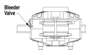
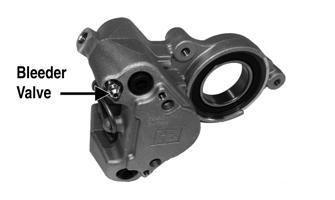
1.Slide a piece of flexible tubing over the ball of the bleeder valve and direct the other end into a container.
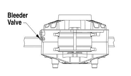
739-269B
2.Slowly compress the brake lever and hold. Open the bleeder valve to release the fluid; then compress the brake lever repeatedly until all brake fluid is expelled. Close the bleeder valve. 3.Add new approved brake fluid to the reservoir; then compress the brake lever and hold. Open the bleeder valve. Repeat the compression until brake fluid flows free of air bubbles and appears clean. NOTE: It may be necessary to refill the reservoir a
number of times to eliminate all air bubbles in the system.
4.When the brake fluid is free of all air and the brake lever feels firm when compressed, fill the reservoir; then install and secure the cover. Remove the tube from the bleeder valve.
5.Bleed the brake system (see BLEEDING BRAKE
SYSTEM in this sub-section).
BLEEDING BRAKE SYSTEM If the brake lever feels spongy when applied, the brake system may need to be bled. 1.With the handlebar in the highest position, remove the reservoir cover and fill the reservoir with approved brake fluid. 2.Slide a piece of flexible tubing over the ball of the bleeder valve and direct the other end into a container.
CAUTION
Brake fluid is highly corrosive. Do not spill brake fluid on any surface of the snowmobile.
! WARNING
Use only approved brake fluid. Any substitute may result in a loss of brakes.
! WARNING
Do not use brake fluid from a container opened for a long period of time. Unsealed brake fluid containers will absorb moisture and can contaminate the fluid inside.

739-269B
3.Slowly compress the brake lever and hold. Open the bleeder valve to release the fluid and air. When the fluid stops flowing, close the bleeder valve; then release the brake lever.
4.Repeat step 3 until the brake fluid flows free of air bubbles.
NOTE: It may be necessary to refill the reservoir
during the bleeding process.
5.When the brake fluid is free of all air and the brake lever feels firm when compressed, fill the reservoir; then install and secure the cover. Remove the tube from the bleeder valve.
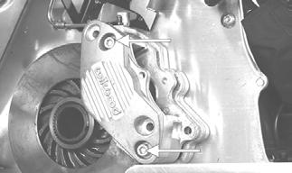
CHECKING AND REPLACING BRAKE PADS 1.Open the right-side access panel and remove the springs and hairpin clip securing the resonator; then remove it from the engine compartment. 2.Disconnect the speed sensor (A); then remove both allen-head screws (B) securing the speed sensor bracket.
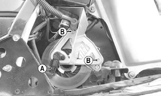
XM105A
3.Remove the hairpin clip from the brake pad retaining pin; then remove the pin. Using a pair of pliers, pull one brake pad out of the caliper assembly.
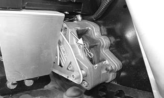
XM106A
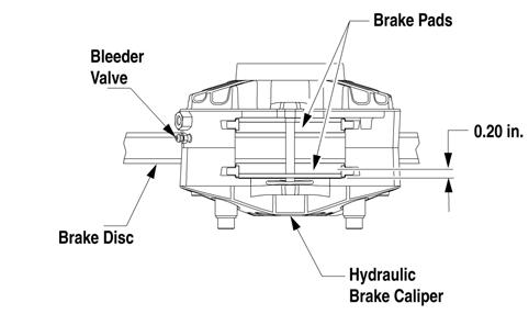
NOTE: Measure the thickness of both brake pads.
The brake pad thickness must be greater than 0.20 in. If the brake pad thickness is less than specified, replacement of both pads is necessary.

0739-269
NOTE: When installing new brake pads, always
install them as a set. Never install just one pad or use brake pads used in another snowmobile.
NOTE: Changing one pad at a time will prevent one
piston from pushing out the other piston from the caliper.
4.Using a flat-blade tool, slowly and carefully push the piston into the caliper. 5.Position the new brake pads into the caliper. 6.Repeat steps 3-5 for the other pad; then secure the pads with the pin and hairpin clip. NOTE: When new brake pads are installed, a “bur-
nishing” process is required. Drive the snowmobile slowly and compress the brake lever several times until the pads just start to warm up; then allow them to cool down. This procedure stabilizes the pad material and extends the life of the pads.
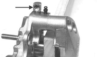
BRAKE CALIPER/BRAKE DISC/DRIVESHAFT BEARING Removing/Disassembling 1.Open the right-side access panel; then remove the springs and hairpin clip securing the resonator to the exhaust pipe and chassis. Remove the resonator. 2.Remove the torx-head cap screws securing the toe shield and hook bracket to the chassis; then remove the shield and bracket. 3.Remove the two allen-head cap screws (B) securing the speedometer sensor mounting bracket to the caliper assembly; then disconnect the speed sensor (A).
Remove the sensor and bracket assembly.
XM105A
4.Engage the brake lever lock; then using Brake Disc
Socket Wrench, remove the retaining nut from the driveshaft.
5.Slide a piece of flexible tubing over the ball of the bleeder valve and direct the other end into a container.
739-269B
CAUTION
Brake fluid is highly corrosive. Do not spill brake fluid on any surface of the snowmobile.
6.Open the bleeder valve and compress the brake lever several times to drain the reservoir of fluid.
7.Remove the brake hose from the caliper. Use an absorbent towel to collect any remaining brake fluid. 8.Disengage the brake lever lock and remove the hairpin clip and pin securing the brake pads; then remove both pads. NOTE: If servicing the brake disc only, remove the
two remaining torx-head cap screws securing the caliper housings together; then remove the outside housing. Account for the O-ring.
ZJ219A
CAUTION
If the caliper housings are to be separated at this time, take care not to allow any contaminants into the fluid passages of the calipers.
NOTE: To aid in removing the inner caliper hous-
ing, completely loosen track tension.
9.Remove the four lock nuts (A) and the Phillips-head cap screw with lock nut (B) securing the caliper housing assembly to the chassis; then remove the inside caliper housing along with the brake disc from the driveshaft. Account for the caliper spacer and the disc spacer.
740-188A
10.If the bearings are to be replaced with the caliper housing secured in a suitable vise, drive the outer bearing out of the housing by using a hammer and sharp flat punch. Tap evenly in a crisscross pattern on the inner race of the bearing until the bearing is out of the housing. Account for the spacer. NOTE: Never reuse bearings that have been
removed. Always use new bearings.
Use care not to bind the bearing in the caliper housing when removing or damage to the housing may occur.
11.Remove the retaining ring securing the inner bearing in the caliper housing.

ZJ245
12.If bearings are to be replaced, place the caliper housing in a suitable clamping device; then using a press, remove the inner bearing from the housing.

ZJ240
NOTE: Never reuse bearings that have been
removed. Always use new bearings.
NOTE: If the caliper housings were separated for
disassembling purposes, they must be secured together with the small O-ring installed between the inner and outer housings.
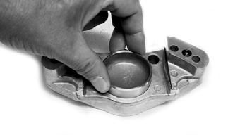
13.Position a piece of wood between the pistons. Using low-pressure compressed air, blow into the caliper brake hose fitting to remove the brake pistons. ! WARNING
Always wear safety glasses when using compressed air.
ZJ228A
NOTE: Remove the two remaining torx-head cap
screws securing the caliper halves. Discard the small O-ring.

MS320A
14.Remove the pistons and O-rings; then discard the
O-rings.

ZJ229
ZJ230 ZJ251A
Cleaning and Inspecting 1.Inspect the brake pistons for gouges, cracks, pitting, scuffing, or corrosion. If any of these conditions exist, replace the piston. NOTE: The inner and outer caliper housings are
not serviceable components. If either or both are defective or damaged, the complete caliper assembly must be replaced.
2.Clean the piston outer surface by using a soft
Scotch-Brite pad and clean brake fluid as a cleaner.
CAUTION
Do not use any sharp cleaning tool on the piston surface or in the O-ring groove as it may cause damage. Parts-cleaning solvent must not be used as it can damage the piston O-ring.
AF230
3.Inspect the piston bore of the inner and outer brake calipers for gouges, cracks, pitting, scuffing, or corrosion. If any of these conditions exist, replace the caliper. 4.Clean the caliper inner wall surface using a soft lint-free cloth and clean brake fluid.
CAUTION
Care must be taken not to allow any contaminants into the fluid passages of the calipers or brake system malfunction may occur.
ZJ225A
MS320A
5.Inspect the condition of the brake pads. Replace if damaged or worn. The brake pad thickness must be greater than 0.20 in. If the brake pad thickness is less than specified, replacement of both pads is necessary.
0739-269
6.Inspect the brake hose for cracks and deterioration and check the condition of the threaded connectors.
Assembling/Installing 1.Apply approved brake fluid to the new O-ring; then install the O-ring into the groove of each caliper half.

ZJ231
CAUTION
Never reuse piston O-rings. Always install new O-rings when installing pistons in the brake caliper.
2.In each caliper half, apply approved brake fluid to the brake piston; then while twisting, install the piston with the dished side facing out.
ZJ229
ZJ230
NOTE: To aid in installing the piston, make sure the
piston O-ring is properly seated in the groove of the caliper housing.
3.Place the small O-ring into position; then assemble the two caliper halves. Secure with the two torx-head cap screws. Tighten only until snug.

ZJ231A
NOTE: Always use a new O-ring and make sure the O-ring is properly seated in the outer brake housing.
MS320A
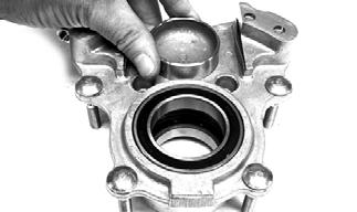
4.Using a suitable press, install a new inner bearing into the caliper housing until it is properly seated.
ZJ241
CAUTION
When installing a bearing, always press on the outer race of the bearing.
ZJ239A
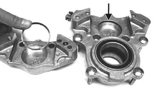
5.Install the snap ring securing the inner bearing in the caliper housing.
ZJ245
6.Install the bearing spacer; then press a new outer bearing into the caliper housing until properly seated.
ZJ244
CAUTION
When installing a bearing, always press on the outer race of the bearing.
NOTE: For aid in installing the outer bearing,
insert a length of shaft (the same diameter as the bearing inner bore) through the inner bearing, driveshaft sleeves, and outer bearing to maintain proper alignment of the driveshaft sleeves for driveshaft installation.

ZJ242
ZJ243
7.Apply Anti-Seize Thread Compound to the splines of the brake disc; then with the brake caliper spacer properly installed, slide the caliper onto the driveshaft far enough to install the spacer and brake disc.

ZJ232
ZJ233
8.With the brake disc splines and driveshaft splines aligned, use a soft hammer and tap the caliper from side to side until the caliper is properly seated to the tunnel.
740-188A
10.Apply Anti-Seize Thread Compound to the threads of the brake disc retaining nut; then install the nut.
Tighten only until snug. NOTE: If the outer caliper housing was removed
during disassembling, install a new O-ring and place the housing into position; then secure with the two Allen-head cap screws. Tighten to 17 ft-lb.
MS320A
ZJ219A
11.Install the brake pads; then secure the brake pads with the retaining pin and hairpin clip. 12.Bleed the brake system (see BLEEDING BRAKE
SYSTEM in this sub-section). 13.Engage the brake lever lock; then using Brake Disc
Socket Wrench, tighten the brake disc retaining nut (from step 10) to 120 ft-lb. NOTE: The brake lever lock must be engaged for
this procedure.

MS323
NOTE: After the retaining nut is tightened to speci-
fications, peen the nut at the flat spot of the driveshaft.
14.Install the speedometer sensor mounting bracket to the caliper housing with the two remaining allen-head cap screws (B); then tighten all four to 17 ft-lb.
739-269B
2.Remove the two screws securing the reservoir cover and remove the reservoir cover; then open the bleeder valve. Allow the brake fluid to drain completely. 3.Place an absorbent towel around the connection to absorb brake fluid. Remove the banjo-fitting bolt (A) securing the brake fluid hose (B) to the master cylinder. Discard the two crush washers.
CAUTION
Brake fluid is highly corrosive. Do not spill brake fluid on any surface of the snowmobile.

XM105A
15.Connect the harness connector (A) to the speedometer sensor plug-in. 16.Install the toe shield and toe hook bracket; then install the torx-head cap screws. Tighten securely. 17.Place the expansion chamber and resonator into position and secure with the springs and the hairpin clip. 18.Adjust track alignment and tension (see Track Tension/Track Alignment in this section).
Brake Lever/Master Cylinder Assembly (2000)
REMOVING 1.Slide a piece of flexible tubing over the ball of the bleeder valve and direct the other end into a container.
742-152A
4.Remove the snap ring (C) and pin (D) securing the brake lever to the master cylinder. 5.Using a small screwdriver, compress the tabs of the brake light switch (E) to release it from the master cylinder. 6.Remove the two torx-head screws (F) and clamp securing the brake reservoir to the handlebar; then place a towel over the reservoir and remove the assembly from the handlebar.
INSPECTING 1.Inspect the snap ring and pin securing the brake lever for wear or damage; then inspect the brake lever for cracks or damage. 2.Inspect the master cylinder reservoir and cover for cracks and leakage. NOTE: The master cylinder is a non-serviceable
component. If any wear or damage is detected, the master cylinder must be replaced.
3.Inspect the brake fluid hose for cracks, deterioration, and the condition of the fittings (threaded and compression).
INSTALLING 1.Position the brake assembly on the handlebar. Secure with two torx-head screws (F) and clamp; tighten securely. 2.Install the brake fluid hose (B) to the master cylinder with the banjo-fitting bolt (A) and two new crush washers. Tighten securely.
3.Install the brake light switch (E) to the master cylinder.
4.Install the brake lever; then secure with pin (D) and snap ring (C). 5.Place the reservoir cover onto the reservoir; then secure with the two screws.
6.Bleed the brake system (see BLEEDING BRAKE
SYSTEM in this sub-section).
CAUTION
Always use new crush washers when installing the brake fluid hose.
Brake System (7000)
CHECKING BRAKE LEVER TRAVEL 1.Compress the brake lever fully. NOTE: Do not pump the brake lever as it will pro-
duce an inaccurate reading.
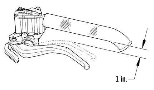
2.Measure the distance between the brake lever and the handlebar. The distance must be greater than 1in.
0745-816
3.If the distance is less than specified, check the brake fluid level (see CHECKING AND ADDING
BRAKE FLUID in this sub-section), inspect for leakage, and check the brake pads (see CHECKING
AND REPLACING BRAKE PADS in this sub-section).
! WARNING
Do not operate the snowmobile if the distance between the compressed brake lever and handlebar is less than 1 in. Brake loss may occur. Brake loss can result in severe personal injury.
CHECKING AND ADDING BRAKE FLUID 1.With brake fluid reservoir in a level position and the cover removed, check the fluid level. The brake fluid level must be at the high mark in the reservoir.

0745-817
2.If the brake fluid level is low, add Arctic Cat approved brake fluid until the fluid is at the recommended level. Install and secure the reservoir cover.
DO NOT allow moisture to contaminate the brake system.
CAUTION
Brake fluid is highly corrosive. Do not spill brake fluid on any surface of the snowmobile.
! WARNING
Do not overfill the brake fluid reservoir. Overfilling the reservoir may cause the brake system to hydraulically lock. Use only approved brake fluid. Never substitute or mix different types or grades of brake fluid. Brake loss may occur. Brake loss can result in severe injury or even death.
CHANGING BRAKE FLUID The brake fluid must be changed on a regular basis and/or whenever the brake fluid has been overheated or contaminated. The brake fluid should be changed every 1000 miles or at the end of the snowmobiling season, whichever occurs first.
Arctic Cat recommends the removal and disassembly of the brake caliper assembly when changing the brake fluid (see BRAKE CALIPER/BRAKE DISC/DRIVESHAFT BEARING in this sub-section).
1.Slide a piece of flexible tubing over the ball of the bleeder valve and direct the other end into a container. CAUTION
Brake fluid is highly corrosive. Do not spill brake fluid on any surface of the snowmobile.
! WARNING
Use only Arctic Cat approved brake fluid. Any substitute may result in a loss of brakes.
PC223A
2.Slowly compress the brake lever and hold. Open the bleeder valve to release the fluid; then compress the brake lever repeatedly until all brake fluid is expelled. Close the bleeder valve. 3.Add new approved brake fluid to the reservoir; then compress the brake lever and hold. Open the bleeder valve. Repeat the compression until brake fluid flows free of air bubbles and appears clean. NOTE: It may be necessary to refill the reservoir a
number of times to eliminate all air bubbles in the system.
4.When the brake fluid is free of all air and the brake lever feels firm when compressed, fill the reservoir; then install and secure the cover. Remove the tube from the bleeder valve.
5.Bleed the brake system (see BLEEDING BRAKE
SYSTEM in this sub-section).
BLEEDING BRAKE SYSTEM If the brake lever feels spongy when applied, the brake system may need to be bled. 1.With the handlebar in the highest position, remove the reservoir cover and fill the reservoir with approved brake fluid.
2.Slide a piece of flexible tubing over the ball of the bleeder valve and direct the other end into a container. CAUTION
Brake fluid is highly corrosive. Do not spill brake fluid on any surface of the snowmobile.
! WARNING
Use only approved brake fluid. Any substitute may result in a loss of brakes.
! WARNING
Do not use brake fluid from a container opened for a long period of time. Unsealed brake fluid containers will absorb moisture and can contaminate the fluid inside.
PC223A
3.Slowly compress the brake lever and hold. Open the bleeder valve to release the fluid and air. When the fluid stops flowing, close the bleeder valve; then release the brake lever.
4.Repeat step 3 until the brake fluid flows free of air bubbles.
NOTE: It may be necessary to refill the reservoir
during the bleeding process.
5.When the brake fluid is free of all air and the brake lever feels firm when compressed, fill the reservoir; then install and secure the cover. Remove the tube from the bleeder valve.
CHECKING AND REPLACING BRAKE PADS 1.Remove the brake shield; then remove the retaining pin securing the brake pads.
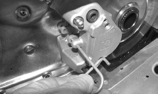
PC195
2.Remove one brake pad and measure the thickness.
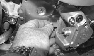
PC196
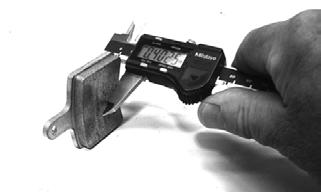
PC199
NOTE: Brake pad thickness must be greater than
0.20 in. If brake pad thickness is less than specified, replacement of both pads is necessary. Always replace with new pads and always replace as a set.
3.Position the new brake pad into the caliper. 4.Repeat for the other pad; then secure the pads with the retaining pin.

PC194
NOTE: When new brake pads are installed, a “bur-
nishing” process is required. Drive the snowmobile slowly and compress the brake lever several times until the pads just start to warm up; then allow them to cool down. This procedure stabilizes the pad material and extends the life of the pads.
BRAKE CALIPER/BRAKE DISC/DRIVESHAFT BEARING Removing/Disassembling 1.Remove both access panels; then remove the drive belt (see Drive Belt in this section) and driven clutch. 2.Remove the screws securing the brake shield and footrest to the chassis; then remove the shield and rest.
3.Slide a piece of flexible tubing over the ball of the bleeder valve and direct the other end into a container.
PC223A
CAUTION
Brake fluid is highly corrosive. Do not spill brake fluid on any surface of the snowmobile.
4.Open the bleeder valve and compress the brake lever several times to drain the reservoir of fluid.
5.Remove the brake hose from the caliper. Use an absorbent towel to collect any remaining brake fluid. 6.Remove the retaining pin securing the brake pads; then remove both pads.
PC195
NOTE: If servicing the brake disc only, remove the cap screws securing the caliper housings together; then remove the outside housing. Account for the seal.
NOTE: To aid in removing the inner caliper hous-
ing, completely loosen track tension.
CAUTION
If the caliper housings are to be separated, take care not to allow any contaminants into the fluid passages of the calipers.
7.Remove the snap ring from the drive shaft and remove the brake disc; then remove the cap screws securing the inner caliper/drive shaft bearing housing to the chassis.
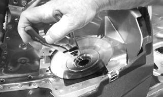
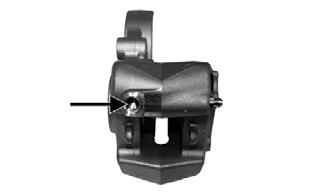
PC174

PC148A
8.If the bearing will be replaced, remove the snap ring; then using a suitable press, remove the bearing from the housing.
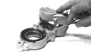
PC200
NOTE: Never reuse bearings that have been
removed. Always use new bearings.
NOTE: If the caliper housings were separated, they
must be secured together with the seal installed between the inner and outer housings.
9.Position a piece of wood between the pistons. Using low-pressure compressed air, blow into the caliper brake hose fitting to loosen the brake pistons. ! WARNING

Always wear safety glasses when using compressed air.
PC221A
10.Remove the two screws securing the caliper halves.
Discard the seal.
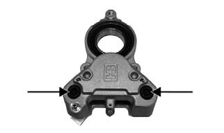
PC219A
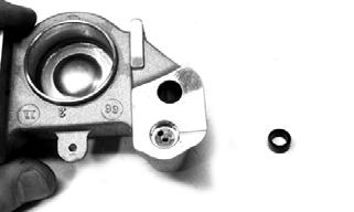
PC173
11.Remove the pistons (A) and O-rings (B); then discard the O-rings.
PC220A
Cleaning and Inspecting 1.Inspect the brake pistons for gouges, cracks, pitting, scuffing, or corrosion. If any of these conditions exist, replace the piston. NOTE: The inner and outer caliper housings are
not serviceable components. If either or both are defective or damaged, the complete caliper assembly must be replaced.
2.Clean the piston outer surface by using a soft
Scotch-Brite pad and clean brake fluid as a cleaner.
3.Inspect the piston bore of the inner and outer brake calipers for gouges, cracks, pitting, scuffing, or corrosion. If any of these conditions exist, replace the caliper. 4.Clean the caliper inner wall surface using a soft lint-free cloth and clean brake fluid.
5.Inspect the condition of the brake pads. Replace if damaged or worn. The brake pad thickness must be greater than 0.20 in. If the brake pad thickness is less than specified, replacement of both pads is necessary. 6.Inspect the brake hose for cracks and deterioration and check the condition of the threaded connectors.
Assembling/Installing 1.Apply approved brake fluid to new O-rings; then install the O-rings into the groove of each caliper half.
2.In each caliper half, apply approved brake fluid to the brake piston; then while twisting, install the piston with the dished side facing out.
CAUTION
Do not use any sharp cleaning tool on the piston surface or in the O-ring groove as it may cause damage.
CAUTION
Care must be taken not to allow any contaminants into the fluid passages of the calipers or brake system malfunction may occur.
CAUTION
Never reuse piston O-rings. Always install new O-rings when installing pistons in the brake caliper.
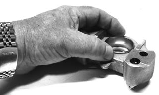
PC201
NOTE: To aid in installing the piston, make sure the
piston O-ring is properly seated in the groove of the caliper housing.
3.Using a suitable press, install a new inner bearing into the caliper housing until it is properly seated.
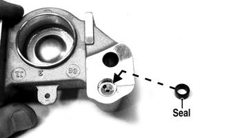
CAUTION
When installing a bearing, always press on the outer race of the bearing.
ZJ239A
4.Install the snap ring securing the bearing in the caliper housing.

PC204
5.Place the inner caliper housing/drive shaft bearing housing onto the drive shaft and secure with the cap screws coated with blue Loctite #243. Tighten to 25 ft-lb. 6.Apply Anti-Seize Thread Compound to the splines of the brake disc; then install on the drive shaft and secure with the snap ring. 7.Install a new seal in the outer caliper fluid passage; them install the outer caliper and secure with the cap screws. Tighten to 25 ft-lb.
PC195
9.Bleed the brake system. 10.Install the brake shield and footrest; then install the drive belt and driven clutch. Tighten the driven clutch cap screw to 20 ft-lb. 11.Adjust the track tension and track alignment. 12.Close and secure both side panels.
Brake Lever/Master Cylinder Assembly (7000)
REMOVING 1.Slide a piece of flexible tubing over the ball of the bleeder valve and direct the other end into a container.
PC223A
2.Remove the two screws securing the reservoir cover and remove the reservoir cover; then open the bleeder valve. Allow the brake fluid to drain completely. 3.Place an absorbent towel around the connection to absorb brake fluid. Remove the banjo-fitting bolt (A) securing the brake fluid hose (B) to the master cylinder. Discard the two crush washers.
CAUTION
Brake fluid is highly corrosive. Do not spill brake fluid on any surface of the snowmobile.
745-759A
4.Remove the pin (D) securing the brake lever to the master cylinder. 5.Using a small screwdriver, compress the tabs of the brake light switch (E) to release it from the master cylinder. 6.Remove the two torx-head screws (F) and clamp securing the brake reservoir to the handlebar; then place a towel over the reservoir and remove the assembly from the handlebar.
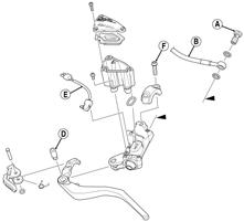
INSPECTING 1.Inspect the snap ring and pin securing the brake lever for wear or damage; then inspect the brake lever for cracks or damage. 2.Inspect the master cylinder reservoir and cover for cracks and leakage. NOTE: The master cylinder is a non-serviceable
component. If any wear or damage is detected, the master cylinder must be replaced.
3.Inspect the brake fluid hose for cracks, deterioration, and the condition of the fittings (threaded and compression).
INSTALLING 1.Position the brake assembly on the handlebar. Secure with two torx-head screws (F) and clamp; tighten securely. 2.Install the brake fluid hose (B) to the master cylinder with the banjo-fitting bolt (A) and two new crush washers. Tighten securely.
3.Install the brake light switch (E) to the master cylinder.
4.Install the brake lever; then secure with pin (D). 5.Place the reservoir cover onto the reservoir; then secure with the two screws.
6.Bleed the brake system.
CAUTION
Always use new crush washers when installing the brake fluid hose.
Troubleshooting Track
Troubleshooting Hydraulic Brake System
Problem: Track Edge Frayed — Drive Lugs Worn Condition Remedy
1. Track alignment adjusted incorrectly 1.Align — replace track
Problem: Track Worn Adjacent to Outer Drive Lugs Condition Remedy
1. Track tension adjusted incorrectly 1.Adjust track tension 2. Rear idler wheels dirty — damaged 2.Clean — replace idler wheels
Problem: Track Ratchets — Slaps Tunnel Condition Remedy
1. Track tension adjusted incorrectly (too loose) 1.Adjust track tension (tighten) 2. Drive sprockets misaligned — damaged 2.Align — replace sprockets
Problem: Wear-Strip Wear Excessive Condition Remedy
1. Slide rail bent — broken — damaged 1.Repair — replace slide rail 2. Track alignment adjusted incorrectly 2.Adjust track alignment
Problem: Caliper Leaks Condition Remedy
1. Caliper O-ring deteriorated — severed 1.Replace O-ring 2. Piston — O-ring damaged 2.Repair piston — replace piston — O-ring
Problem: Lever Spongy — Bottoms Out Condition Remedy
1. Brake system air bubbles present 1.Bleed brake system 2. Master cylinder damaged — faulty 2.Replace master cylinder
Problem: Oscillation Feedback in Lever Condition Remedy
1. Brake pad residue present on brake disc 1.Replace pads — clean disc 2. Caliper loose 2.Tighten mounting bolts
Problem: Loss of Brake Condition Remedy
1. Brake fluid overheated — contaminated 1.Replace fluid 2. Master cylinder damaged — faulty 2.Replace master cylinder 3. Caliper — brake hose leaking 3.Replace caliper O-ring — repair piston —replace piston — O-ring — brake hose 4. Brake lever linkage damaged 4.Repair — replace lever — mounting bolt
Problem: Brakes Drag Condition Remedy
1. Master cylinder damaged — faulty 1.Replace master cylinder 2. Brake pads worn — tapered 2.Replace pads
Problem: Snowmobile Won’t Stop — Have to Pull Too Hard on Lever Condition Remedy
1. Pads/brake disc glazed 1.Replace pads — clean disc 2. Brake lever binding 2.Loosen pivot bolt — replace master cylinder 3. Caliper pistons binding 3.Service caliper assembly
Troubleshooting Drive Clutch/Driven Clutch
Problem: Midrange Shift-Up (Too Quickly - Lowers RPM) Condition Remedy
1. Drive clutch spring weak 1.Replace drive clutch spring 2. Driven clutch spring weak 2.Replace driven clutch spring 3. Driven clutch spring preload tension inadequate 3.Replace driven clutch spring 4. Center-to-center distance too close 4.Adjust center-to-center distance 5. Driven clutch bearing worn — damaged 5.Replace bearing — movable sheave
Problem: Midrange Shift-Up (Too Slowly - Raises RPM) Condition Remedy
1. Drive clutch components dirty 1.Clean drive clutch components 2. Driven clutch components dirty 2.Clean driven clutch components 3. Driven clutch spring preload tension excessive 3.Replace driven clutch spring 4. Driven clutch bearing worn — dirty 4.Clean — replace bearing — movable sheave
Problem: Excessive Belt Deposits Condition Remedy
1. Offset/parallelism incorrect 1.Adjust offset/parallelism 2. Drive clutch/driven clutch sheaves rough — damaged — 2.Repair — replace — clean drive clutch/driven clutch dirty 3. Driven clutch movable sheave travel impaired 3.Service driven clutch 4. Driven clutch bearing worn — dirty 4.Clean — replace bearing — movable sheave
Problem: Excessive Belt Drag—Impaired Drive Clutch Disengagement Condition Remedy
1. Drive clutch components dirty — damaged 1.Clean — replace drive clutch components 2. Drive belt does not meet measurement specifications 2.Replace drive belt
Problem: Engine RPM Suddenly Increases—Drive Clutch Vibrates Condition Remedy
1. Cam arm pin bent — damaged 1.Replace pin 2. Cam arm damaged — broken 2.Replace cam arm 3. Drive clutch out of balance 3.Align — replace components — drive clutch — drive belt
Problem: Driven Clutch Vibrates Condition Remedy
1. Driven clutch out of balance 1.Service — replace driven clutch
Problem: Drive Clutch Engagement (Before Specified RPM) Condition Remedy
1. Drive clutch spring weak — bent 1.Replace spring 2. Cam arms incorrect — worn 2.Replace cam arms
Problem: Drive Clutch Engagement (After Specified RPM) Condition Remedy
1. Drive clutch spring incorrect 1.Replace spring 2. Spider buttons worn 2.Replace clutch
Problem: Drive Clutch Sticks Condition Remedy
1. Drive clutch components dirty 1.Clean drive clutch components 2. Movable sheave bent — binding 2.Clean — replace movable sheave 3. Spider buttons worn 3.Replace clutch
Problem: Drive Clutch Jerks—Shifts Erratically Condition Remedy
1. Drive clutch dirty 1.Clean — drive clutch components 2. Rollers worn 2.Replace clutch 3. Cam arms rough 3.Polish — replace cam arms 4. Spider buttons worn 4.Replace clutch 5. Sheaves dirty 5.Clean sheaves