25 minute read
Steering/Body/Controls

The following steering components should be inspected periodically to ensure safe and proper operation:
A.Handlebar grips not worn, broken, or loose.
B.Handlebar not bent, cracked, and has equal and complete full-left and full-right turning capability.
C.Steering post bearing assembly/bearing housing not broken, worn, or binding.
D.Ball joints not worn, cracked, or damaged.
E.Tie rods not bent or cracked.
F.Knuckles not worn, cracked, or damaged.
G.Cotter pins not damaged or missing. The frame, welds, and racks should be checked periodically for damage, bends, cracks, deterioration, broken components, and missing components.
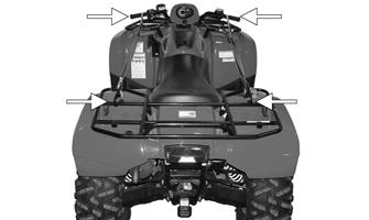
Front Body Panel/Side Panels
REMOVING 1.Remove the reinstallable rivets securing the radiator access cover and remove the cover; then remove four reinstallable rivets securing the steering post cover and remove the cover.
FI465A
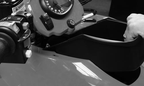
2.Unlock the storage compartment lid; then slide the storage compartment cover assembly forward and lift off the storage compartment.
FI467
3.Remove the storage compartment box; then remove the seat.
FI468
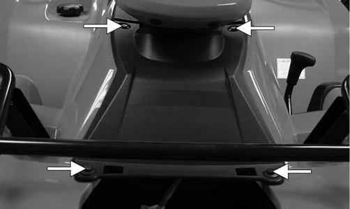
4.Remove the ignition switch retaining ring and two reinstallable rivets securing the instrument pod. Disconnect the harness from the instrument pod and accessory plug; then remove the instrument pod.

CF724A

FI464A
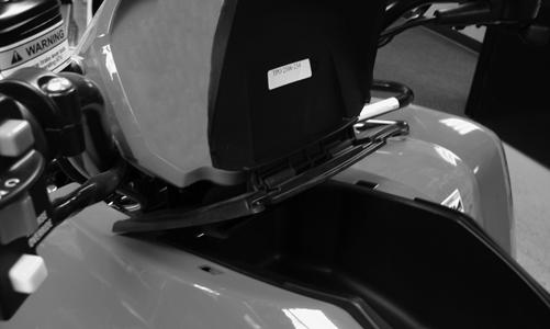
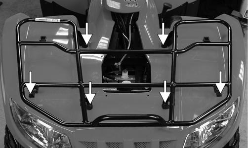
5.Remove the cap screws and lock nuts securing the front rack to the frame; then remove the front rack.
Account for the grommets and bushings.
FI469A
6.Remove the side panels by pulling on them to release the tabs from the body; then remove the screws securing the rear of the front panel to the frame.

CF237A

FI470A
7.Remove the left and right footwells; then remove the shift knob. Remove the shift lever pivot axle nut and remove the axle and shift lever. Account for a spring and two O-rings.
CD779

CD780A
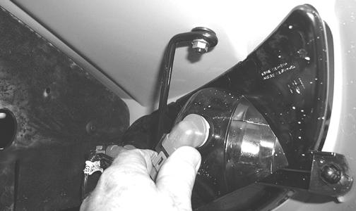
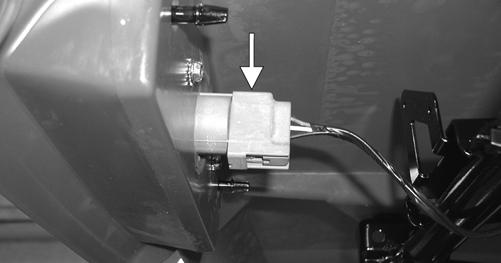
8.Disconnect four headlight connectors and secure the wires out of the way; then disconnect the wires to the front accessory plug.
CD681
9.Rotate the handlebar to the full-left position; then lift and slide the panel to the rear and lift the rear up to clear the handlebar.
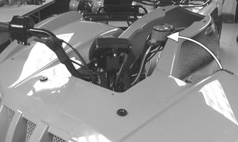
CD765A
NOTE: It may be necessary to rotate the body panel to the right to align the opening with the handlebar.
CLEANING AND INSPECTING 1.Clean all fender components with warm soap and water.
2.Inspect fenders for cracks. 3.Inspect for any missing decals.
INSTALLING 1.Rotate the handlebar to the full-left position; then place the front body panel over the handlebar and rotate and lower into position.

CD765
2.Connect the headlight connectors to the appropriate headlights and the front accessory plug wires to the accessory plug.
CD681
3.Make sure the rubber grommets and bushings are in place; then place the front rack into position and secure with the cap screws and lock nuts. Tighten securely. 4.Install the footwells and footrests. Tighten securely. 5.Install the cap screws securing the front body panel to the frame and rear panel.
FI470A
6.Install the shift lever spring, shift lever, and pivot axle; then tighten the axle nut securely.
CD779
7.Connect the wire harness to the indicator display and accessory outlet. Install the instrument pod and ignition switch; then secure with two reinstallable rivets and the ignition switch retaining ring. 8.Set the storage compartment box into position; then install the storage compartment cover making sure the mounting tabs engage the slots. Slide rearward to secure and lock by engaging the lid lock.
FI468

FI467
9.Install the steering post cover and secure with the reinstallable rivets; then install and secure the radiator access panel.
FI466A
FI465A
10.Install the side panels.
Rear Body Panel/Rack
REMOVING 1.Remove the cap screws and lock nuts securing the rear rack; then remove the rear rack. Account for the bushings. Note the gas tank ventilation bracket installed location.
CF668A
2.Remove the cap screws and lock nuts securing the rear body panel to each footwell.

CF669
3.Remove two machine screws securing the battery cover and remove the cover.

CD687A
4.Disconnect the battery (negative cable first); then remove the battery. 5.Disconnect the taillight/brake light; then remove the gas tank cap and lift off the rear body panel. Install the gas tank cap. NOTE: If the front body panel has not been
removed, the left-side and right-side panels and the two machine screws must be removed (see Front Body Panel/Side Panels in this section).
CLEANING AND INSPECTING 1.Clean all rear body panel components with warm soap and water. 2.Inspect side panels and rear body panel for cracks.
3.Inspect threaded areas of all mounting bosses for stripping. 4.Inspect for missing decals.
INSTALLING 1.Remove the gas tank cap and set the rear body panel in position; then install the cap and connect the taillight/brake light connector. 2.Place the rear rack in position with the bushings and secure with the cap screws and lock nuts. Tighten securely. Secure the gas tank ventilation bracket to the frame using the rear rack cap screw and lock nut. 3.Secure the cap screws and lock nuts securing the rear body panel to each foot well.
CF669
4.Place the battery into the battery box; then connect the battery (positive cable first) and secure with the battery cover.
CD687A
5.Secure the front and rear panels with two machine screws; then install the left and right side panels. NOTE: If the front body panel has not been
installed, see Front Body Panel/Side Panels in this section.
6.Place the seat into position making sure it locks securely.
LCD Gauge
NOTE: Certain models are equipped with an LCD
gauge.
REPLACING 1.Remove the two reinstallable rivets securing the instrument pod; then remove the ignition switch retaining ring. Disconnect the harness from the accessory outlet. 2.Remove the two nuts securing the mounting studs; then remove the gauge and disconnect the multi-pin connector.
3.Mount the gauge and secure with the two nuts; then connect the multi-pin connector and accessory outlet. 4.Install the instrument pod and secure with the reinstallable rivets.
5.Secure the ignition switch with the retaining ring.
Indicator Display
REPLACING 1.Remove the two reinstallable rivets securing the indicator display; then remove the ignition switch retaining ring. Disconnect the harness from the accessory outlet. 2.Remove the two nuts securing the mounting studs; then remove the indicator and disconnect the multi-pin connector. 3.Mount the indicator and secure with the two nuts; then connect the multi-pin connector and accessory outlet.
4.Install the indicator display and secure with the reinstallable rivets.
5.Secure the ignition switch with the retaining ring.
Steering Post/Tie Rods
REMOVING 1.Remove the ignition switch retaining ring; then remove the reinstallable rivets securing the instrument pod to the mounting bracket and remove the pod and indicator display.
CF724A
FI464A
2.Remove the reinstallable rivets securing the radiator access cover and remove the cover.
FI465A
3.Remove four reinstallable rivets securing the steering post cover and remove the cover.
FI466A
4.Unlatch the storage compartment lid; then slide the storage compartment cover assembly forward and lift off.


FI468A
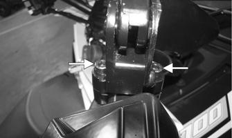
6.Remove the four cap screws securing the handlebar caps and indicator display/gauge bracket to the steering post; then move the handlebar and gauge out of the way. Account for four handlebar caps.

CF659
7.Remove two cap screws securing the upper steering post bearing to the frame. Account for two steering post mounting blocks and steering post mounting bracket.
CF660
8.Using a suitable lift stand, raise the ATV enough to remove the front wheels.
NOTE: For models not equipped with electronic
power steering, proceed to step 13.
9.Remove the left front shock absorber; then remove the cap screws and nuts from the steering post to the
EPS couplers.
EPS005A
10.Pull upward on the handlebar to disengage the upper coupler from the EPS assembly. 11.Disconnect the 2-pin and 8-pin connectors from the top of the EPS housing.

EPS007A
12.Remove four cap screws securing the EPS housing to the frame; then lift the assembly upward sufficiently to disengage the lower coupler and remove from the left side.
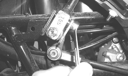
13.Remove the cotter pins and slotted nuts from the inner and outer tie rod ends; then remove the tie rods from the steering post arm and the left-side and right-side steering knuckles.
CAUTION
Do not attempt to disassemble the EPS assembly as there are no serviceable components within the assembly and damage will occur voiding the EPS warranty.
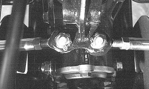
AF778D KX039
14.Remove two cap screws securing the lower steering post bearing flange to the frame; then remove the steering post.

AL600D
CLEANING AND INSPECTING 1.Clean and inspect the pivot area for wear. Apply a low-temperature grease to the ends.
2.Inspect the tie rods for damaged threads or wear. 3.Inspect the tie rods for cracks or unusual bends. 4.Inspect all welded areas for cracks or deterioration. 5.Inspect the steering post and steering-post brackets for cracks, bends, or wear. 6.Inspect the bearing halves, bearing caps, and bearing housings for cracks or wear. 7.Inspect the handlebar tube for cracks, wear, or unusual bends.
8.Inspect the handlebar grips for damage or wear.
INSTALLING (models without EPS) 1.Place the steering post into position; then secure the lower bearing flange to the frame with two cap screws. Tighten to 20 ft-lb.
! WARNING
Always wear safety glasses when using compressed air.
AL600D
2.Place the upper steering post mounting blocks into position; then insert the two shoulder screws through the frame and thread them into the steering post mounting bracket. Tighten to 20 ft-lb.

CF671
3.Install the tie rods and secure with the slotted nuts.
Tighten to 30 ft-lb; then install new cotter pins. NOTE: If the slots do not align with the holes in the
tie rod ends, tighten the nuts just enough to allow installation of the cotter pins.

AF778D
4.Install the front wheels using a crisscross pattern, tighten the wheel nuts in 20 ft-lb increments to a final torque of 40 ft-lb (steel wheel), 60 ft-lb (aluminum wheel w/black nuts), or 80 ft-lb (aluminum wheel w/chrome nuts). 5.Lower the ATV and place the handlebar and caps into position on the steering post; then position the bracket on top of the caps and secure with the four cap screws. Tighten securely. 6.Install the storage compartment box; then attach the storage compartment cover assembly by engaging the tabs into the slots and sliding rearward. Lock the storage compartment lid to hold the assembly in place. 7.Place the instrument pod into position; then secure with two reinstallable rivets and the ignition switch retaining ring.
FI464A
CF724A
8.Install the steering post access cover and secure with four reinstallable rivets; then install and secure the radiator access cover.
FI466A
FI465A
INSTALLING (Electronic Power Steering models) 1.Place the lower steering post into position; then secure the lower bearing flange to the frame with two cap screws. Tighten to 20 ft-lb.
AL600D
2.Making sure the double spline is aligned to the slot in the lower coupler, install the EPS output shaft into the lower coupler; then install the four caps screws securing the EPS housing to the frame. Tighten to 35 ft-lb.
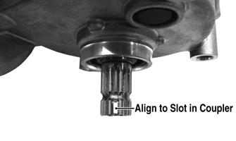
EPS008A EPS007
3.Install the tie rods and secure with the slotted nuts.
Tighten to 30 ft-lb; then install new cotter pins. NOTE: If the slots do not align with the holes in the
tie rod ends, tighten the nuts just enough to allow installation of the cotter pins.

AF778D
EPS005A
4.Connect the 2-pin and 8-pin connectors to the EPS assembly. 5.Install the upper steering post support to the frame and secure with two cap screws. Tighten to 20 ft-lb.

CF671
6.Install the storage compartment, steering post and radiator access panels, and storage compartment cover; then install the shock absorber and tighten to 50 ft-lb.
7.Install the front wheels using a crisscross pattern, tighten the wheel nuts in 20 ft-lb increments to a final torque of 40 ft-lb (steel wheel), 60 ft-lb (aluminum wheel w/black nuts), or 80 ft-lb (aluminum wheel w/chrome nuts).
Handlebar Grip
INSPECTING/REMOVAL 1.Inspect the grip for wear, cuts, or cracks. 2.Inspect the grip for deterioration.
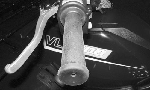
CF747
3.If a grip is damaged, cut the grip lengthwise using a sharp knife or box cutter; then peel off the grip.
INSTALLING NOTE: Before installing a grip, use contact removal
spray or alcohol to clean the handlebar of glue residue, oil, or any other contaminant.
1.Apply a liberal amount of Handlebar Grip Adhesive to the inside of a new grip. 2.Slide the grip onto the handlebar until it is fully seated with the smooth part of the grip facing up. 3.Wipe off any excess glue.
REMOVING 1.Remove the two machine screws securing the throttle control to the handlebar.

CF725A
2.Slide the grommet out of the lower half of the throttle control; then remove the cable from the actuator arm.

AF676D
3.Remove the cap screw, lock washer, and washer securing the actuator arm to the throttle control lever.

AF677D
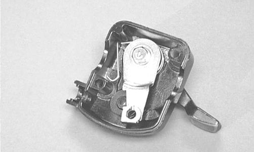
4.Remove the actuator arm and account for a bushing.
Note the position of the return spring for installing purposes.

AF678D
INSTALLING 1.Place the return spring into the throttle control; then place the bushing and actuator arm into position.
Secure with the cap screw, lock washer, and washer.
AF679D
2.Using a pair of needle-nose pliers, place the spring into position on the actuator arm.
AF680D
3.Place the two halves of the throttle control onto the handlebar and secure with the two machine screws.
CF725A
ADJUSTING To adjust throttle cable free-play, see Fuel/Lubrication/ Cooling.
Steering Knuckles
REMOVING AND DISASSEMBLING 1.Secure the ATV on a support stand to elevate the wheel; then remove the wheel.
2.Remove the wheel cap from the hub; then remove the cotter pin from the nut. 3.Remove the nut securing the hub. 4.Remove the brake caliper.
! WARNING
Make sure the ATV is solidly supported on the support stand to avoid injury.
NOTE: Do not allow the brake caliper to hang from
the cable/hose.
5.Remove the hub assembly. 6.Remove the cotter pin from the tie rod end and remove the tie rod end from the knuckle.
7.Remove the two cap screws securing the ball joints in the knuckle.
8.Tap the ball joint end out of the knuckle; then remove the knuckle.
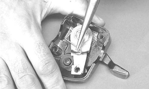
9.Remove the snap ring from the knuckle; then remove the bearing.

PR288
CAUTION
Use extreme care when removing the bearing. If the bearing is allowed to fall, it will be damaged and will have to be replaced.
CLEANING AND INSPECTING 1.Clean all knuckle components. 2.Inspect the bearing for pits, gouges, rusting, or premature wear.
3.Inspect the knuckle for cracks, breaks, or porosity. 4.Inspect threads for stripping or damage.
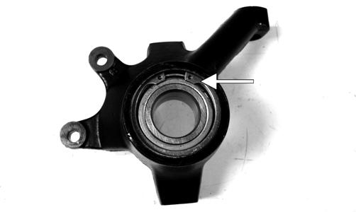
ASSEMBLING AND INSTALLING 1.Install the bearing; then install the snap ring making sure it seats into the knuckle.
PR287A
2.Install the knuckle to the upper and lower ball joints and secure with the two cap screws. Tighten to 35 ft-lb. 3.Install the tie rod end and secure with the nut.
Tighten to 30 ft-lb; then install a new cotter pin and spread the pin. NOTE: During assembling, new cotter pins should
be installed.


XR338
4.Apply a small amount of grease to the hub splines.
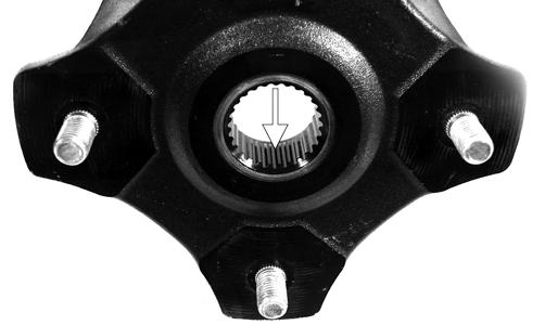
PR290A
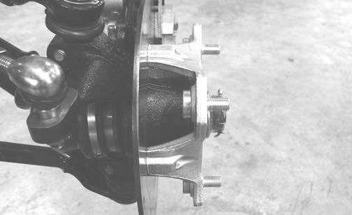
5.Install the hub assembly onto the splines of the shaft. 6.Secure the hub assembly with the nut. Tighten only until snug.
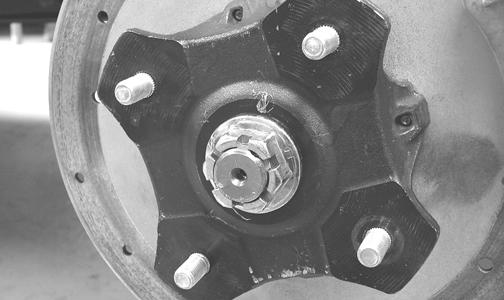
PR257
7.Secure the brake caliper to the knuckle with new
“patch-lock” cap screws. Tighten to 20 ft-lb.

PR264A
8.Pump the hand brake lever; then engage the brake lever lock.
9.Using an appropriate hub retaining wrench, secure the hub nut (from step 6) to the shaft. Tighten to 200 ft-lb.
10.Install a new cotter pin and spread the pin to secure the nut.
11. Install the wheel; then using a crisscross pattern, tighten the wheel nuts in 20 ft-lb increments to a final torque of 40 ft-lb (steel wheel), 60 ft-lb (aluminum wheel w/black nuts), or 80 ft-lb (aluminum wheel w/chrome nuts). 12.Remove the ATV from the support stand.
Front Wheel Alignment
1.Thoroughly wash the ATV to remove excess weight (mud, etc.); then ensure the tires are properly inflated to the recommended pressure. 2.Place the unloaded ATV in a level position taking care not to push down or lift up on the front end; then turn the handlebar to the straight ahead position. 3.Measure the distance from the outside edge of each handlebar grip to equal reference points on each side. 4.Adjust the handlebar direction until the two measurements are equal; then secure the handlebar to the rear rack using tie-down straps. NOTE: Care must be taken not to allow the handle-
bar to turn while securing it.
5.Mark the center line of the front tires at the front and the rear of the tire; then using a tape measure, measure and record the distance between the marks at the front and rear. The front measurement should be 3-6 mm (1/8-1/4 in.) greater than the rear measurement (toe-out).

WT292A
6.Using an open-ended wrench to hold the tie rod (A), loosen the right and left jam nuts (B).

CF344A
CAUTION
Always use a wrench to hold the tie rod in place when loosening either of the jam nuts or damage to the boots could occur.
7.Turn the left- and right-side tie rods in equal increments to achieve proper toe out; then place a drop of red Loctite #271 on the threads and while holding the tie rod, tighten each jam nut to 35 ft-lb.
Shift Lever
REMOVING 1.Remove the E-clip securing the shift rod to the shift lever.
2.Remove two cap screws, two self-tapping screws, and three nylon ties securing the left-side splash panel and remove the panel. 3.Remove the axle and nut securing the shift lever to the upper shift arm; then remove the shift lever.
Account for a spring and two O-rings.
INSTALLING 1.Place the spring into position between the upper shift arm and shift lever; then making sure the O-rings are in place on the axle, secure the shift lever to the arm with the existing axle and nut. 2.Place the shift rod into position on the shift lever and secure with the existing E-clip. 3.Check shift lever adjustment (see Periodic Maintenance/Tune-Up); then tighten jam nut(s) securely. 4.Install the left-side splash panel.
2WD/4WD Shift Lever
REMOVING NOTE: Prior to loosening the jam nut (A), measure
the set length of the adjuster (B).
1.Loosen the jam nut (A); then align the slots in the adjuster (B), jam nut, and shift lever mount (C).
Remove the cable from the shift lever.
CF741A
2.Remove the two cap screws securing the shift lever assembly to the handlebar.

CF742A
INSTALLING 1.Place the lower clamp under the handlebar; then secure the main assembly on top with the two cap screws. Tighten securely. 2.Place the cable end into the lever. With the slots from the jam nut and adjuster aligned, lower the cable in place. Place the end of the cable housing into the adjuster and tighten the jam nut. Adjust the set length at the lever assembly. 3.Adjust the cable. The main cable adjuster is located within the front left wheel well. Pull the rubber cover (A) away, loosen the jam nut (B), and turn the adjuster (C).

CF743A
Front Rack
REMOVING 1.Remove the cap screws and lock nuts securing the rack to the frame and front fender panel. 2.Remove the front rack from the ATV.
CLEANING AND INSPECTING 1.Clean all rack components using a pressure washer. 2.Inspect all welds for cracking or bending. 3.Inspect threaded areas of all mounting bosses for stripping. 4.Inspect for missing decals and/or reflectors.
INSTALLING 1.Place the rack into position on the frame and front fender panel. Install the cap screws and lock nuts and finger-tighten only. 2.Install the two cap screws and lock nuts securing the rack to the fenders. Tighten all hardware securely.
Front Bumper Assembly
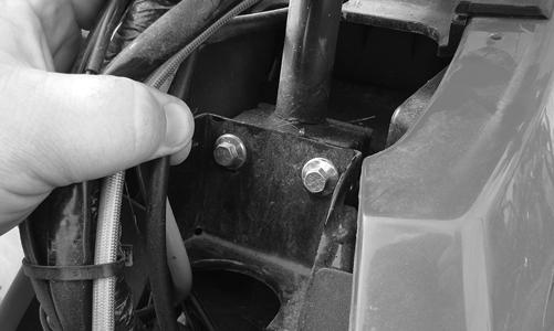
REMOVING 1.Remove the two flange bolts securing the upper bumper supports to the frame bracket. 2.Remove the two lower cap screws securing the bumper to the frame; then remove the bumper.
CLEANING AND INSPECTING 1.Clean all bumper components with parts-cleaning solvent.
2.Inspect all welds for cracking or bending.
INSTALLING 1.Place the front bumper assembly into position and install the lower cap screws. Finger-tighten only.
Footrests
REMOVING 1.Remove the machine screws and flange nuts securing the front and rear fenders to the footwells.
CF669
2.Remove the screws and flange nuts securing the foot pegs to the footrests; then remove the foot pegs and footwells.
3.Remove the cap screws and flange nuts securing the footrests to the frame; then remove the footrests.
CLEANING AND INSPECTING 1.Clean the footrest in parts-cleaning solvent. 2.Inspect the footrest weldments for cracks or unusual bends.
3.Inspect all tubing for cracks or unusual bends.
INSTALLING 1.Secure the footrests to the frame with four cap screws and two flange nuts; then tighten the 8 mm hardware to 20 ft-lb and the 10 mm hardware to 40 ft-lb.
2.Place the footwells onto the footrests; then put the foot pegs in position and secure with two cap screws. 3.Install the machine screws and flange nuts securing the front and rear fenders to the footwells.
Belly Panel
REMOVING/INSTALLING 1.Remove the machine screws and shoulder washers securing the belly panel to the underside of the frame; then remove the belly panel. 2.Place the belly panel into position on the underside of the frame; then install the machine screws and shoulder washers. Tighten securely.
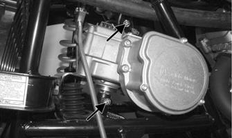
REMOVING 1.Remove the two exhaust springs at the muffler/exhaust pipe juncture.
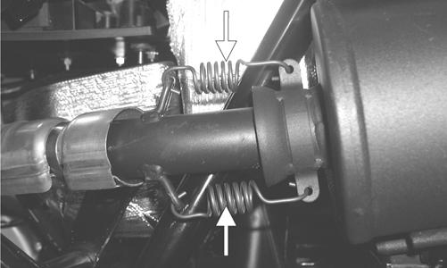
CF138A
2.Slide the muffler rearward to clear the mounting lugs and remove the muffler.
INSPECTING 1.Inspect muffler externally for cracks, holes, and dents.
2.Inspect the muffler internally by shaking the muffler back and forth and listening for rattles or loose debris inside the muffler.
NOTE: For additional details on cleaning the muf-
fler/spark arrester, see Periodic Maintenance/Tune-Up.
INSTALLING 1.Place the muffler into position engaging the mounting lugs into the grommets; then slide the muffler forward.
2.Install the two exhaust springs.
Taillight Assembly
REMOVING 1.Unplug the three-prong connector and free the taillight wiring harness from the frame. 2.Remove the Torx-head cap screws securing the taillight assembly to the body. Account for any washers. 3.Remove the taillight assembly.
INSPECTING 1.Inspect wiring harness, three-prong connector, lens, base, cap screws, and socket for damage. 2.Inspect all wires for corroding, pinching, and cracking. 3.Inspect the bulb for wattage, voltage, and proper operation.
INSTALLING 1.Place the assembly into position on the body and secure with Torx-head cap screws and any washers. 2.Tighten the cap screws securely. 3.Route the wiring harness over the rear frame; then connect the three-prong connector.
Seat
REMOVING/INSTALLING
1.To remove the seat, lift up on the latch release (located at the rear of the seat). Raise the rear of the seat and slide it rearward. 2.To lock the seat into position, slide the front of the seat into the seat retainers and push down firmly on the rear of seat. The seat should automatically lock into position.
Headlights — Taillight/ Brake Light
NOTE: The bulb portion of a headlight is fragile. HANDLE
WITH CARE. When replacing a headlight bulb, do not touch the glass portion of the bulb. If the glass is touched, it must be cleaned with a dry cloth before installing. Skin oil residue on the bulb will shorten the life of the bulb.
! WARNING
Do not attempt to remove a bulb when it is hot. Severe burns may result.
To replace a headlight bulb, use the following procedure: 1.Rotate the bulb assembly counterclockwise and remove from the headlight housing; then disconnect from the wiring harness. 2.Connect the new bulb assembly to the wiring harness connector; then insert into the headlight housing and rotate fully clockwise. To replace the taillight-brake light bulb, use the following procedure: 1.Turn the bulb socket assembly counterclockwise and remove from the housing.
CF132A
3.Insert the bulb socket assembly into the housing and turn it clockwise to secure. CHECKING/ADJUSTING HEADLIGHT AIM
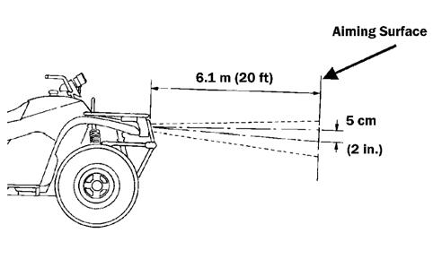
The headlights can be adjusted vertically and horizontally. The geometric center of the HIGH beam light zone is to be used for vertical and horizontal aiming. 1.Position the ATV on a level floor so the headlights are approximately 6.1 m (20 ft) from an aiming surface (wall or similar aiming surface).
ATV-0070C
NOTE: There should be an average operating load on the
ATV when adjusting the headlight aim.
2.Measure the distance from the floor to the mid-point of each headlight. 3.Using the measurements obtained in step 2, make horizontal marks on the aiming surface. 4.Make vertical marks which intersect the horizontal marks on the aiming surface directly in front of the headlights. 5.Switch on the lights. Make sure the HIGH beam is on. DO
NOT USE LOW BEAM. 6.Observe each headlight beam aim. Proper aim is when the most intense beam is centered on the vertical mark 5 cm (2 in.) below the horizontal mark on the aiming surface. 7.Adjust each headlight by turning the adjuster knob clockwise to raise the beam or counterclockwise to lower the beam.
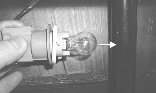
CF135A
2.Pull the bulb straight out of the socket; then insert a new bulb.

Troubleshooting
Problem: Handling too heavy or stiff Condition Remedy
1. Front wheel alignment incorrect 1.Adjust alignment 2. Lubrication inadequate 2.Lubricate appropriate components 3. Tire inflation pressure low 3.Adjust pressure 4. Tie rod ends seizing 4.Replace tie rod ends 5. Linkage connections seizing 5.Repair — replace connections
Problem: Steering oscillation Condition Remedy
1. Tires inflated unequally 1.Adjust pressure 2. Wheel(s) wobbly 2.Replace wheel(s) 3. Wheel hub cap screw(s) loose — missing 3.Tighten — replace cap screws 4. Wheel hub bearing worn — damaged 4.Replace bearing 5. Tie rod ends worn — loose 5.Replace — tighten tie rod ends 6. Tires defective — incorrect 6.Replace tires 7. A-arm bushings damaged 7.Replace bushings 8. Bolts — nuts (frame) loose 8.Tighten bolts — nuts
Problem: Steering pulling to one side Condition Remedy
1. Tires inflated unequally 1.Adjust pressure 2. Front wheel alignment incorrect 2.Adjust alignment 3. Wheel hub bearings worn — broken 3.Replace bearings 4. Frame distorted 4.Repair — replace frame 5. Shock absorber defective 5.Replace shock absorber
Problem: Tire wear rapid or uneven Condition Remedy
1. Wheel hub bearings worn — loose 1.Replace bearings 2. Front wheel alignment incorrect 2.Adjust alignment 3. Tire inflation pressure incorrect 3.Adjust pressure
Problem: Steering noise Condition Remedy
1. Cap screws — nuts loose 1.Tighten cap screws — nuts 2. Wheel hub bearings broken — damaged 2.Replace bearings 3. Lubrication inadequate 3.Lubricate appropriate components