28 minute read
Steering/Body/Controls

The following steering components should be inspected periodically to ensure safe and proper operation. A.Steering wheel secure. B.Steering has equal and complete full-left and fullright turning capability. C.Steering sector mounting bolts tight. D.Ball joints not worn, cracked, or damaged. E.Tie rods not bent or cracked.
F.Knuckles not worn, cracked, or damaged. G.Cotter pins not damaged or missing. H.Steering wheel tilt locks securely. The frame and welds should be checked periodically for damage, bends, cracks, deterioration, broken components, and missing components.
Steering Wheel
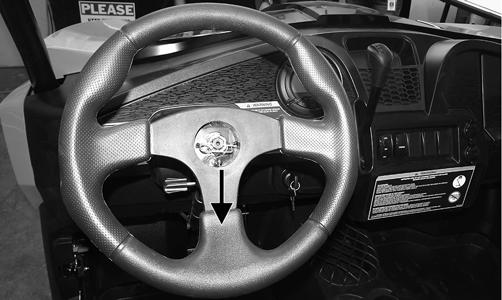
REMOVING 1.Remove the steering wheel cover; then match mark the steering shaft and steering wheel. NOTE: Any time steering components are disassem-
bled, all connecting components should be marked for proper alignment during assembling.
2.Remove the lock clip from the steering shaft; then remove the nut securing the steering wheel and remove the steering wheel. INSPECTING 1.Inspect the steering wheel for cracks, missing padding, or broken spokes. 2.Inspect the splines for wear. 3.Check that the steering wheel is not bent. INSTALLING 1.Install the steering wheel aligning the two match marks; then apply a drop of red Loctite #271 to the threads of the nut and secure the steering wheel.
Tighten to 25 ft-lb. NOTE: If a new steering wheel is being installed,
mark the wheel as close as possible to the old wheel mark; then check for proper positioning with the front wheels straight forward.
2.Install the lock clip on the steering shaft. NOTE: If the hole in the steering shaft does not
align with the slots in the castle nut, tighten the nut slightly until the next slot aligns with the hole.
PR899
Steering System
REMOVING STEERING SHAFT/EPS ASSEMBLY NOTE: Thoroughly troubleshoot the EPS system (if
equipped) prior to replacing the EPS assembly (see Electrical System - Electronic Power Steering (EPS)) as there are several possible external causes for system failure.
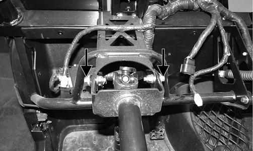
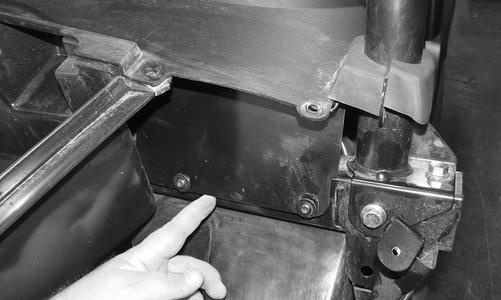
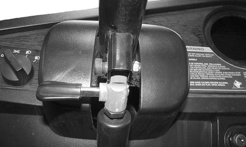
1.Remove the hood, front access panel, and front fenders; then disconnect the regulator/rectifier and remove the screws securing the coolant bottle to the front storage box. 2.Remove the front storage box; then remove the steering wheel. 3.Disconnect the tilt steering mechanism from the steering shaft; then remove the shift lever knob. 4.Disconnect the wiring harness connectors from the back of the dash; then remove the dash. 5.Remove the two cap screws securing the steering shaft housing to the frame.
PR897A
NOTE: Steps 6 and 7 are for non-EPS models. For
EPS models, complete steps 8-11.
6. Make matching alignment marks on the pinion shaft and steering shaft joint.
PR333A
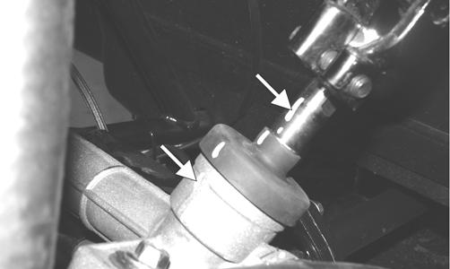
7.Remove the cap screw and lock nut securing the lower steering shaft joint to the pinion shaft; then slide the joint free of the pinion. Discard the lock nut.
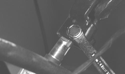
PR302
8.Make matching alignment marks; then disconnect the cap screw and lock nut securing the steering shaft to the EPS assembly. Discard the lock nut.
PR917
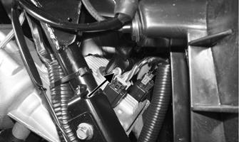
9.Disconnect the two EPS connectors. 10.Remove the cap screws securing the EPS assembly to the frame; then remove the cap screw securing the rack coupler to the EPS output shaft.
PR761A
NOTE: The EPS assembly is not a serviceable com-
ponent and must be replaced as a complete assembly.
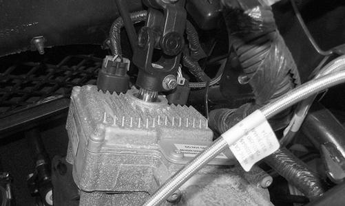
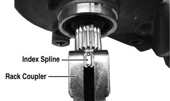
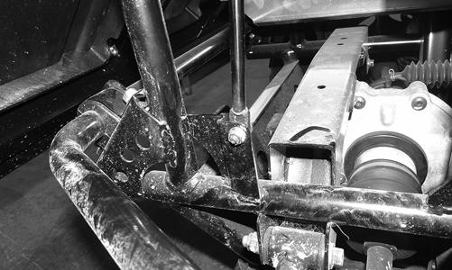
11.Remove the EPS from the top side. INSTALLING STEERING SHAFT/EPS ASSEMBLY 1.Install the EPS into position. 2.Align the slot in the rack coupler to the notch in the frame (front wheels centered).
PR766A
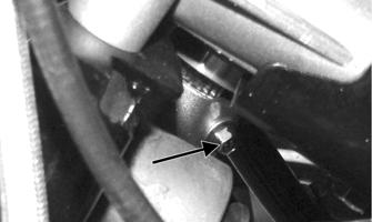
3.On the non-EPS models, insert the steering rack coupler into the pinion shaft using the matching alignment marks. Secure with the cap screw and a new lock nut. Tighten to 25 ft-lb. NOTE: Steps 4-6 are for the EPS models only. 4.Rotate the EPS shaft to align the index (flattened) spline with the slot in the rack coupler and install the
EPS assembly into the coupler; then seat the EPS firmly onto the frame.
PR776A
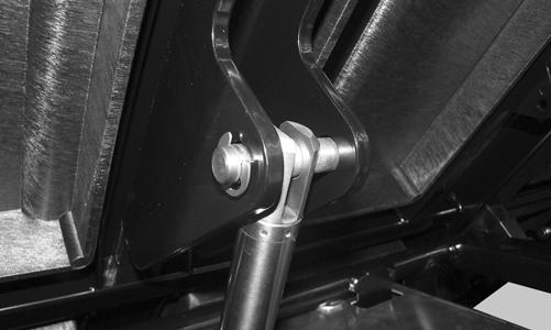
5.Install the cap screws securing the EPS assembly to the frame and tighten to 35 ft-lb. Install the cap screw and new lock nut in the EPS to rack coupler and tighten to 11 ft-lb. 6.Connect the two electrical connectors; then align the slot in the steering shaft coupler to the index (flattened) spline on the EPS input shaft and install.
Install but do not tighten the cap screw.
PR759B
7.Install the steering shaft housing. Secure to the frame with two cap screws and nuts. Tighten to 20 ft-lb.

PR897
8.Tighten the cap screw (from step 6) to 25 ft-lb. 9.Install the front storage box. 10.Connect the regulator/rectifier and install the coolant bottle to the front storage box. Tighten the regulator/ rectifier to 8 ft-lb and the coolant bottle to 48 in.-lb. 11.Install the dash and connect the electrical connectors.
Secure with screws and tighten securely. Do not over-tighten. 12.Connect the tilt steering mechanism and tighten securely. Install the shift knob. 13.Install the front access panel, front fenders, and hood. 14.Install the steering wheel (see Steering Wheel in this section). REMOVING RACK AND PINION NOTE: If equipped, the EPS assembly must be
removed prior to removing the steering assembly.
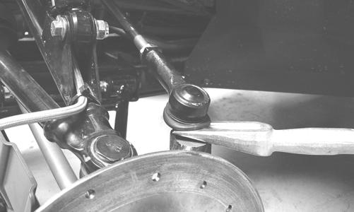
1.Remove the front wheels. 2.Remove the cotter pins and nuts securing the tie rod ends to the knuckles; then remove the tie rod ends from the knuckles.
PR301
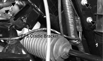
3.Remove the EPS cradle bracket; then remove the cap screws securing the steering rack assembly to the rack bracket and remove from the left side. INSPECTING RACK AND PINION 1.Inspect the tie rod ends for damaged threads, torn boots, or excessive wear. 2.Inspect the tie rods for bends or deformation. 3.Inspect the rack and pinion-to-tie rod boots for tears or deterioration.
PR785
4.Check boot clamps for security. 5.Check that the steering assembly operates smoothly with no binding from full-left to full-right position. 6.Inspect for grease seepage from the steering assembly. NOTE: The steering assembly (rack and pinion) is
not repairable and must be replaced as an assembly; however, the tie rods and boots are replaceable.
INSTALLING RACK AND PINION 1.From the left side, install the steering assembly (rack and pinion) to the frame assembly and secure with two cap screws. Tighten to 35 ft-lb. 2.Install the EPS cradle bracket and secure with four cap screws. Do not tighten the cap screws at this time.
PR773A
3.Place the tie rod ends into the knuckles and secure with the castle nuts (coated with red Loctite #271).
Tighten to 30 ft-lb; then install new cotter pins. NOTE: If the slots in the castle nut are not aligned
with the hole in the tie rod end, tighten until the cotter pin can be installed.
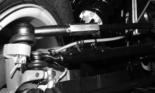
4.Install the EPS assembly; then tighten the cap screws (from step 2) to 20 ft-lb. 5. Install the wheels and using a crisscross pattern, tighten the wheel nuts in 20 ft-lb increments to a final torque of 40 ft-lb (steel wheel), 60 ft-lb (aluminum wheel w/black nuts), or 80 ft-lb (aluminum wheel w/ chrome nuts). REMOVING TIE RODS 1.Remove the steering rack assembly (see REMOV-
ING RACK AND PINION in this section). 2.Support the steering rack assembly in a suitable holding fixture or bench vise; then cut the securing band and slide the boot toward the outer tie rod end. 3.Using a punch or chisel, bend the lock washer away from the flats on the tie rod joint.
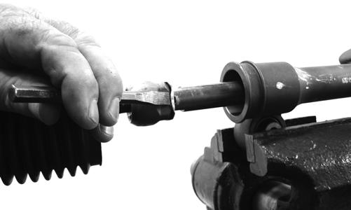
PR780
4.Using an appropriate crow-foot and backing wrench, remove the tie rod assembly. NOTE: Tie rods come as a complete assembly. No
further disassembly is required.
5.Remove and discard the lock washer. INSTALLING 1.Remove the tie rod end and lock nut from the tie rod; then install the tie rod boot onto the tie rod. 2.Install the tie rod lock nut and tie rod end. 3.Coat the tie rod joint threads with red Loctite #271; then with a new lock washer, thread the tie rod into the rack.
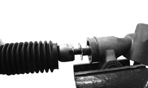
PR784
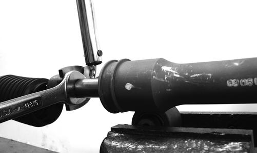
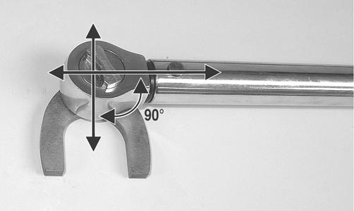
4.While holding the rack shaft with a wrench, tighten the tie rod joint to 37 ft-lb using an appropriate crowfoot.
PR781
NOTE: Always attach the crow-foot to the torque
wrench with the open end 90° to the torque wrench handle to ensure accurate torque application.
PR528A
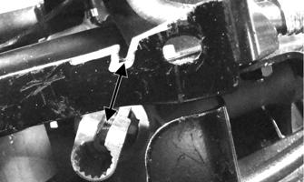
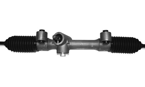
5.Install the boot onto the rack and secure with the nylon tie. 6.Center the rack in the steering rack assembly and align the white paint line on the pinion with the mark on the rack housing.
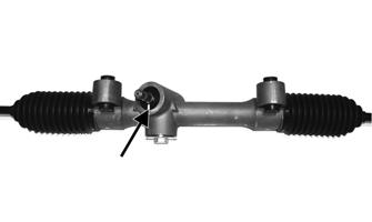
PR785A
Steering Knuckles
REMOVING AND DISASSEMBLING 1.Secure the vehicle on a support stand to elevate the wheel; then remove the wheel and retaining plate. ! WARNING
Make sure the vehicle is solidly supported on the support stand to avoid injury.
2.Remove the nut securing the hub. 3.Remove the brake caliper. 4.Remove the hub assembly. 5.Remove the cotter pin from the tie rod end and remove the tie rod end from the knuckle. 6.Remove the two cap screws securing the ball joints in the knuckle.
PR193
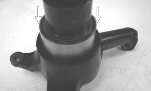
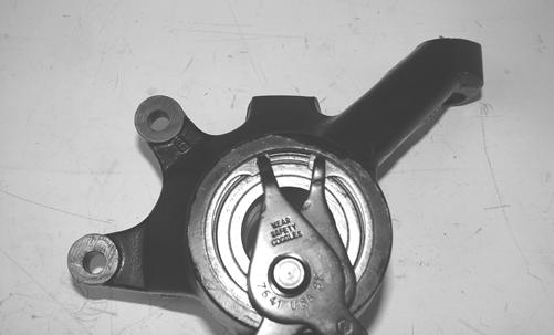
7.Tap the ball joint end out of the knuckle; then remove the knuckle. 8.Remove the snap ring securing the bearing in the knuckle; then press the bearing out of the knuckle.
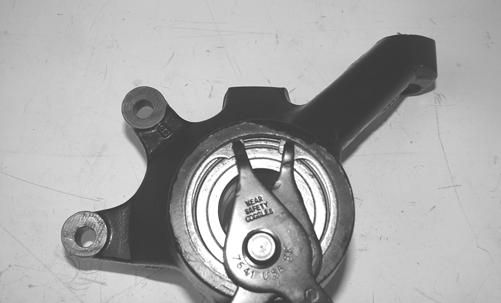
PR289
CLEANING AND INSPECTING 1.Clean all knuckle components. 2.Inspect the bearing for pits, scoring, rusting, or premature wear. 3.Inspect the knuckle for cracks, breaks, or galling of the bearing surface. ASSEMBLING AND INSTALLING 1.Using a suitable press and driver, press the bearing into the knuckle until firmly seated; then install the snap ring.
PR292A
PR289
2.Install the knuckle to the upper and lower ball joints and secure with the two cap screws. Tighten to 35 ftlb.
PR202
PR203
3.Install the tie rod end and secure with the nut (coated with red Loctite #271). Tighten to 30 ft-lb; then install a new cotter pin and spread the pin. NOTE: During assembling, new cotter pins should
be installed.
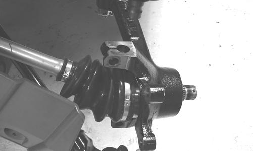
4.Apply a small amount of molybdenum grease to the hub splines.
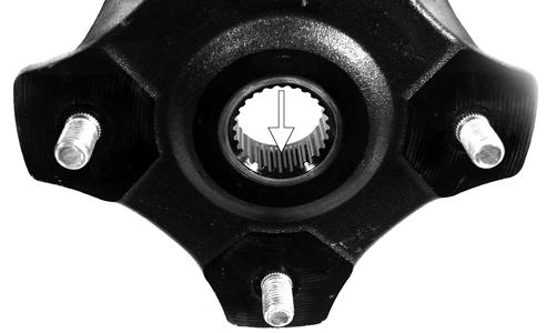
PR290A
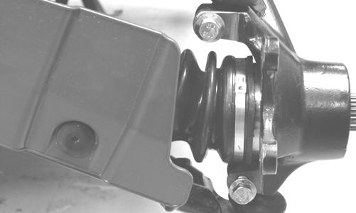
5.Install the hub assembly onto the splines of the shaft.
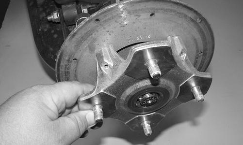
PR961
6.Using Hub Retaining Wrench, secure the hub assembly with the nut. Tighten to 200 ft-lb.
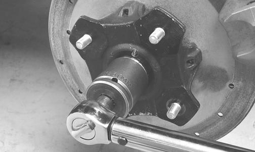
PR256
7.Install the retaining plate. NOTE: If necessary, tighten the hub nut clockwise
to allow the retaining plate to sit flush with the hub.
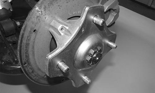
PR965
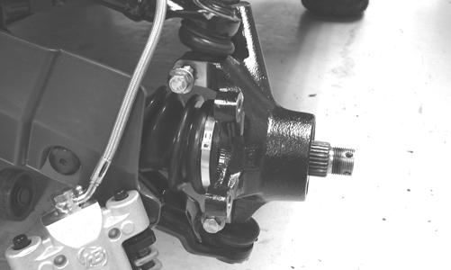
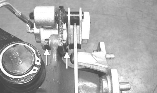
8.Secure the brake caliper to the knuckle with the two new “patch-lock” cap screws. Tighten to 20 ft-lb.
9. Install the wheels and using a crisscross pattern, tighten the wheel nuts in 20 ft-lb increments to a final torque of 40 ft-lb (steel wheel), 60 ft-lb (aluminum wheel w/black nuts), or 80 ft-lb (aluminum wheel w/ chrome nuts). 10.Remove the vehicle from the support stand.
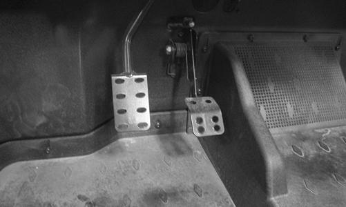
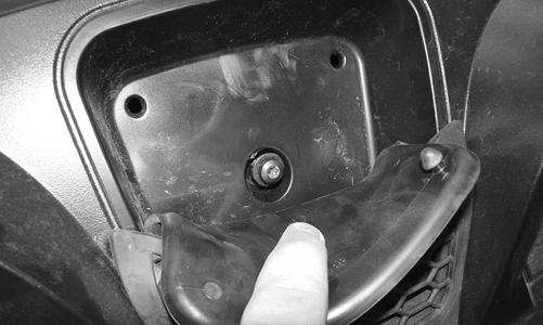
Accelerator Pedal
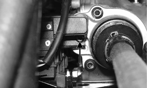
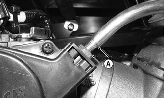
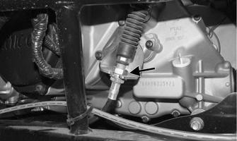
REMOVING Dislodge the throttle cable holding grommet from the actuator arm; then remove two torx-head screws and nuts securing the accelerator pedal assembly to the splash panel and remove the accelerator pedal. 3.Measure the threaded installed set length (A) of the throttle cable housing at the throttle body. This thread length will be used to reset the throttle cable free-play once the throttle cable has been re-routed.
HDX412A
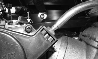
4.Remove the cap screw(s) securing the throttle body cover; then remove the cover.
PR709
HDX309
INSTALLING Align the mounting holes with the holes in the splash panel and secure with the two torx-head screws and nuts; then snap the throttle cable holding grommet into the actuator arm.
Throttle Cable
REMOVING 1.Disconnect the throttle cable from the accelerator pedal. 2.Lift up on the front of the seat to remove it; then remove the cap screws securing the seat back and seat base to access the throttle body. Remove the center and main floorboard panels.
HDX412B
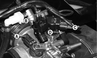
5.Loosen the throttle cable housing jam nut (A); then remove the cable from the throttle body.
HDX418A
6.Hold the end of the throttle cable housing; the throttle cable should move freely in and out of the housing.
NOTE: If the throttle cable does not move freely, the
throttle cable MUST be replaced.
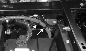
7.Mark all existing cable tie locations securing the throttle cable to the chassis; then remove and discard all cable ties securing the throttle cable to the chassis including one anchored cable tie located at the front of the vehicle below the master cylinder.
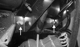
8.Pull the throttle cable all the way through to the front of the vehicle as re-routing of the throttle cable will begin from under the front of the hood. When routing the cable, ensure the cable is clear of any coolant lines, the driveshaft, and any pinch points. INSTALLING 1.Using the previously marked cable tie locations from step 7, use new cable ties to secure the main harness and brake line to the chassis.
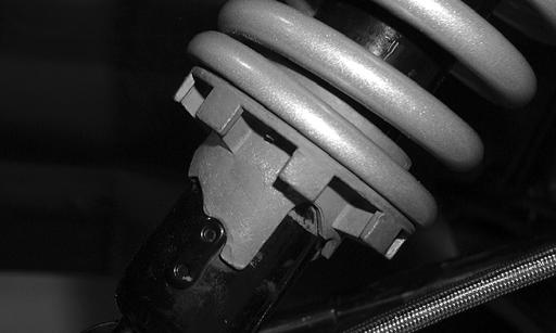
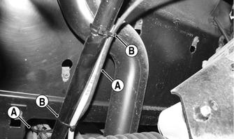
2.Starting on the front left side of the vehicle, route the throttle cable (A) up and over the frame tubing near the top shock mount toward the right side of the vehicle. Secure using a new cable tie (B) in the location shown.
NOTE: Be sure the first bend is up as shown to
help keep water out of the cable.
HDX413A
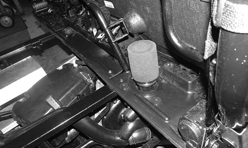
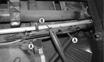
3.From within the front right fender well, secure the throttle cable (A) along the frame (behind the radiator) using new cable ties (B).
HDX414A
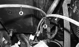
4.Route the throttle cable (A) down along the right side of the frame and through the front splash panel.
Secure using new cable ties as shown (B).
HDX415A
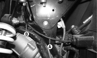
5.Route the throttle cable (A) toward the engine on the right side of the vehicle. Secure using a new cable tie (B) in the location shown.
HDX416A
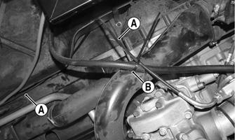
6.Bring the throttle cable (A) up and over the CVT duct and fuel line; then install a new cable tie (B) in the location shown.
HDX417A
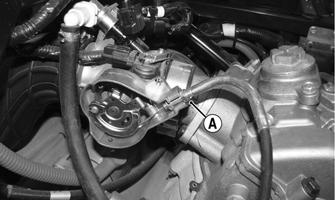
7.Hold the end of the throttle cable housing; the throttle cable should move freely in and out of the housing. 8.Place the end of the throttle cable into the throttle body lever. Secure the throttle cable housing to the throttle body using the jam nut (A). Ensure the threaded set length is adjusted correctly using the measurement from step 2.
HDX418A
9.Install the throttle cable onto the accelerator pedal. NOTE: If the throttle cable does not move freely,
the throttle cable MUST be replaced.
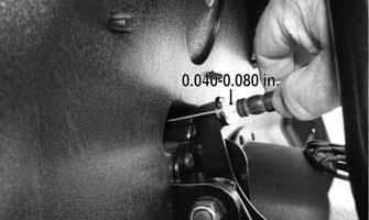
10.Check cable free-play by grasping the cable at the top of the accelerator pedal and lightly pulling rearward to remove slack. Free-play should be 0.0400.080 in. (1-2 mm).
PR708A
11.Depress the accelerator pedal completely and pull rearward on the cable end. There should not be any free-play and the tension sleeve should not be compressed.
HDX426
12.To adjust the throttle cable, remove the throttle body cover; then loosen the two jam nuts and adjust for proper free-play. 13.Tighten the jam nuts securely. Install the throttle body cover. Install the floorboard panels, seat base, seat back, and seat.
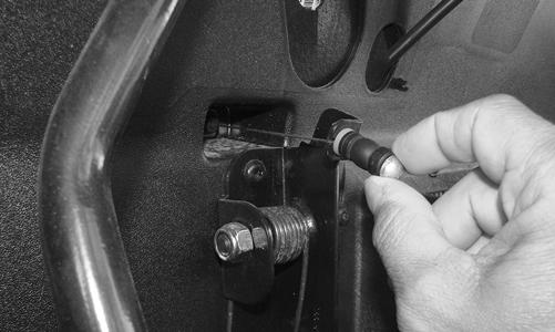
REMOVING 1.Remove the plastic push-pin from the shift lever knob; then remove the knob. 2.Remove the cap screw and lock nut securing the shift lever to the shift cable. Discard the lock nut. 3.Remove the cap screw and lock nut securing the shift lever to bottom pivot location (underneath the dashboard). Slide the shift lever down and out. Discard the lock nut.
PR924A
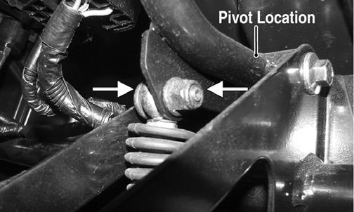
INSTALLING 1.Slide the shift lever up through the opening; then secure to the pivot using the existing cap screw and new lock nut. 2.Secure the shift lever to the shift cable using the existing cap screw and a new lock nut. 3.With the knob in position, install the plastic pushpin. 4.Check for proper shifter operation (see Periodic
Maintenance/Tune-Up - Shift Cable).
Shift Cable
REMOVING 1.Remove the seat, seat back, seat base, and center footrest. 2.Remove the cap screw and lock nut securing the shift cable to the shift lever.

PR924A
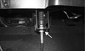
3.From under the dash, loosen the cable adjuster nut; then slide the cable forward out of the bracket.
HDX261A
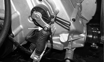
4.Remove the E-clip securing the cable end to the shift arm stud.
HDX251C
5.Loosen the adjuster nut; then remove the shift cable from the bracket. Remove any cable ties securing the shift cable to the chassis noting their location; then remove the shift cable.
HDX262A
NOTE: If the cable is being replaced, connect the
new cable to the end of the existing cable and pull the new cable into place.
INSTALLING 1.Route the cable into position making sure there are no kinks or sharp bends. 2.Guide the shift cable into the shift cable bracket.
Install the cable end to the shift arm stud and secure with a new E-clip. Secure the adjuster nut to the bracket.
HDX251C
3.From under the dash, guide the shift cable into the bracket and secure the cable end to the shift lever using a new locknut. Secure the adjuster nut to the bracket.
HDX261A
4.Fasten the shift cable to the chassis with the previously noted cable tie locations.
5.Shift the transmission through all positions making sure the each gear position illuminates the appropriate gears selected and that Park Indicator illuminates only when fully in Park. Adjust as necessary. 6.Install the center footrest, seat base, seat back, and seat.
LCD Gauge
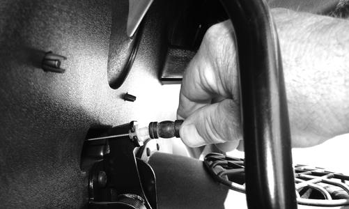
REMOVING/INSTALLING To remove the gauge, pull out on one side of it; then disconnect the multi-pin connector and remove the gauge.
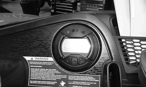
PR900
To install the gauge, connect the multi-pin connector and press the gauge into the dash. NOTE: Ensure the rubber mounting ring is ori-
ented correctly on the tab and seats fully through the dash.
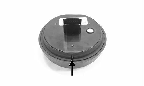
WT601A
Front Wheel Alignment
NOTE: All measurements and adjustments must be
made with the vehicle unloaded.
Mark the center-line of the front tires at the front and rear of the tire; then using a tape measure, measure and record the distance between the marks at the front and rear. The front measurement should be 0-6 mm (0-1/4 in.) greater than the rear measurement (toe-out).
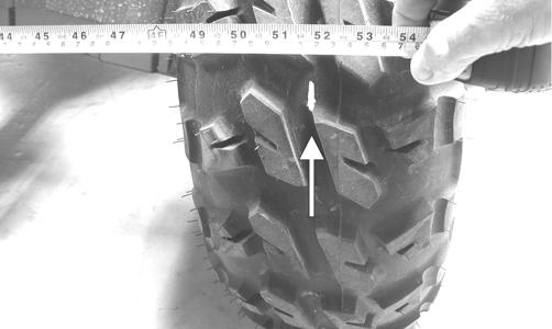
PR087A
1.Center the steering wheel; then using an open-end wrench to hold the tie rod ends, loosen the right-side and left-side jam nuts.
UTV-374B
PR792
CAUTION
Always use a wrench to hold the tie rod ends when loosening or tightening the jam nuts or damage to the boots could occur.
2.Turn the left-side and right-side tie rods in equal increments to achieve the proper toe-out; then tighten the jam nuts to 8 ft-lb.
Front Fascia/Front Bumper
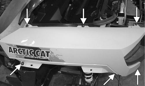
REMOVING 1.Lift the hood and remove the access cover seal; then remove the push pins securing the front access panel and remove the panel.
PR890A
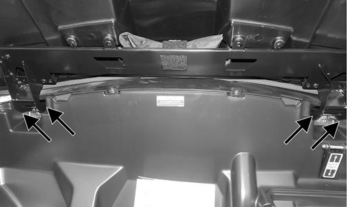
2.Remove the cap screws securing the outer fender; then remove the inner front fenders from both sides of the vehicle. 3.Remove the cap screws securing the upper front fascia; then remove the cap screws securing the lower front fascia.
HDX302A
HDX303A
4.Disconnect the both headlight assemblies; then remove both headlight retaining clips and headlight adjuster screw from each assembly. Reference mark then release the headlight harness anchors from the front bumper.
HDX304
HDX305A
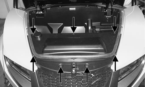
5.Remove the cap screws and nuts securing the top side of the radiator to the front bumper. Disconnect the radiator fan connector. Secure the radiator in place. 6.Reference mark then release any remaining harness anchors from the front bumper. From under the hood, remove the two cap screws securing the bottom of the front storage box to the front bumper.
HDX306A
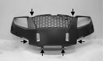
7.Remove the four cap screws and two lock nuts securing the front bumper to the frame; then lift the bumper up and over the radiator to remove. Discard the lock nuts.
HDX307A
HDX308
INSTALLING 1.Place the front bumper into position and secure with the four cap screws and new lock nuts. Tighten to 20 ft-lb.
HDX307A
HDX308
2.From under the hood, install the two cap screws securing the bottom of the front storage box to the front bumper. Using the previously marked harness anchor locations, install the anchors to the front bumper. 3.Secure the radiator to the front bumper and connect the radiator fan to the wiring harness. 4.Install both headlight assemblies onto the front bumper and secure with the retaining clips. Install the headlight adjuster screws.
HDX304
HDX305A
5.Secure the lower front fascia to the frame followed by the upper front fascia.
HDX303A
HDX302A
6.Install the inner then outer front fenders to the vehicle. Place the front access panel into position and secure with the plastic push pins. Install the access cover seal. 7.Check and adjust headlight aim (see Headlight - Taillight/ Brakelight section).
Hood
REMOVING 1.Open the hood; then remove the four cap screws securing the hood hinges to the frame.
PR902A
2.Remove the hood assembly. CLEANING AND INSPECTING 1.Clean all hood components with soap and water. 2.Inspect the hood for cracks and/or loose fasteners. 3.Inspect for any missing decals. INSTALLING Place the hood into position on the vehicle; then secure with the cap screws. Tighten securely.
Front Fenders
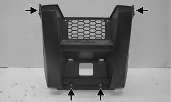
REMOVING 1.Remove the four cap screws securing each outer fender to the corresponding inner fender; then remove the fenders. 2.Remove the push pins securing the front access panel. Tilt the access panel back to access the inner fender fasteners.
PR890A
3.Remove the remaining cap screws securing the inner fender from the inside of the headlight assembly, storage tray, and frame.
PR944A
INSTALLING 1.Install the inner fenders and secure using the existing cap screws. 2.Install the access panel and secure with the push pins. 3.Secure the outer fenders to the vehicle using the existing cap screws.
Floor
REMOVING 1.Remove the seat, seat back, and seat base. 2.Remove the self-tapping screws securing both side panels to the frame. 3.Remove the center floorboard.
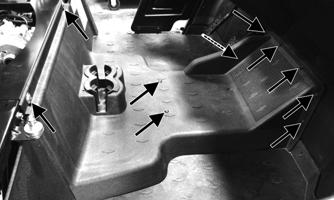
HDX132A
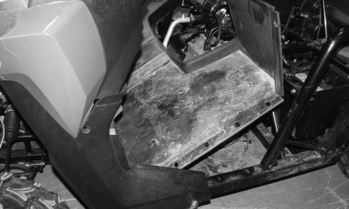
4.Remove the four cap screws securing the left side panel.
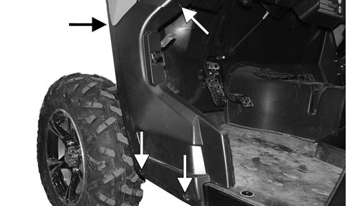
PR932A
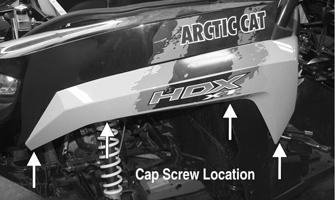
5.Remove the screws securing the side panel to the kick panel; then remove the cap screws securing the kick panel to the frame.
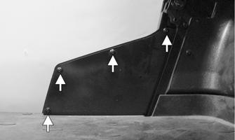
HDX265A
PR933
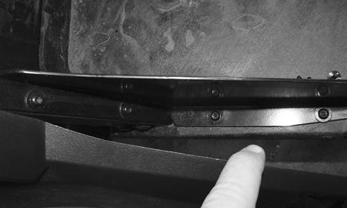
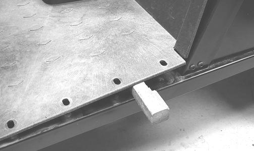
6.Repeat steps 4-5 for the right side. 7.Remove the remaining cap screws and self-tapping screws securing the floor board to the frame. 8.While pulling forward on the upper-rear of the floorboard, lift the rear part of the floor above the seat locating stud.
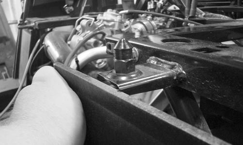
HDX310
NOTE: To aid in removing, insert a small wood
block to hold in position.
PR164
9.From the opposite side of the vehicle, repeat step 8; then lift the rear of the floor up and lift the floor out of the vehicle.
PR945
CLEANING AND INSPECTING 1.Clean the floor with soap and water. 2.Inspect the floor for cracks or holes. INSTALLING 1.Place the front of the floor into position in the vehicle first; then lower the rear and push past the seat locating studs.
2.Secure the floor with the cap screws and self-tappings screws. 3.Install the center floorboard. 4.Install the seat base, seat back, and seat.
Dashboard
REMOVING 1.Remove the steering wheel, shift lever knob, and front access panel.
PR890A
2.Remove the hood seal; then disassemble and remove all four front fenders (outer fenders first).
HDX267A
HDX268A
3.Remove the cap screws around the perimeter of the dashboard.
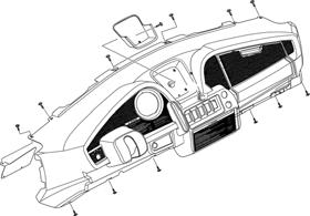
ROV-887
4.From under the dashboard, disconnect the accessory plugs, override switch, drive select switch, and ignition switch. Note the orientation of the connectors for installing purposes. 5.Remove the instrument gauge from the dashboard and disconnect it; then remove the cap screws securing the steel access plate on the driver’s side behind the dashboard. Disconnect the headlight switch connector.
HDX269
6.Remove the upper cap screw and lock nut from the tilt steering sub-assembly and support lift. Discard the locknut.
HDX270
7.Slowly pull away the top of the center dash pad and remove the final cap screw. Remove the dashboard.
HDX271
INSTALLING 1.Install the dashboard into position. Install but do not tighten the cap screw behind the center dash pad.
HDX271
2.Secure the tilt steering sub-assembly to the support lift with the cap screw and new lock nut. Connect the headlight switch connector; then install the steel access panel with two cap screws. 3.Install and connect the gauge to the dashboard. 4.From under the dash, connect the ignition switch, drive select switch, override switch, and accessory plugs. 5.Install and secure the remaining cap screws around the perimeter of the dashboard including the one behind the center dash pad. 6.Install both inner front fenders; then install the outer fenders.
HDX268A HDX267A
7.Install the front access panel, hood seal, and shift lever knob. 8.Align and install the steering wheel (see Steering
Wheel in this section).
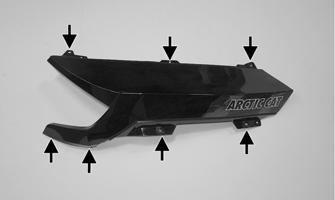
Belly Panel
REMOVING 1.Remove the body screws securing the belly panel to the underside of the frame. 2.Remove the belly panel. INSTALLING 1.Place the belly panel into position on the underside of the frame. 2.Install the body screws. Tighten securely.
Muffler
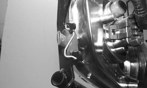
REMOVING 1.Remove the two exhaust springs at the muffler/ exhaust pipe juncture.
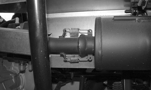
HDX286
2.Slide the muffler assembly clear of the holder pins. INSPECTING 1.Inspect muffler externally for cracks, holes, and dents.
2.Inspect the muffler internally by shaking the muffler back and forth and listening for rattles or loose debris inside the muffler.
NOTE: For additional details on cleaning the muffler/
spark arrester, see Periodic Maintenance/Tune-Up.
INSTALLING 1.Place the muffler onto the holder pins and slide into position. 2.Secure the muffler to the exhaust pipe with the two exhaust springs.
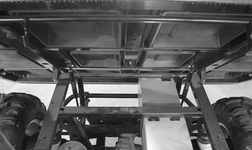
Cargo Box
REMOVING 1.Remove the muffler and heat shield.
HDX298
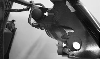
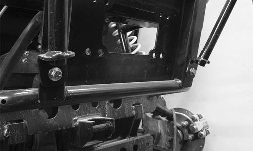
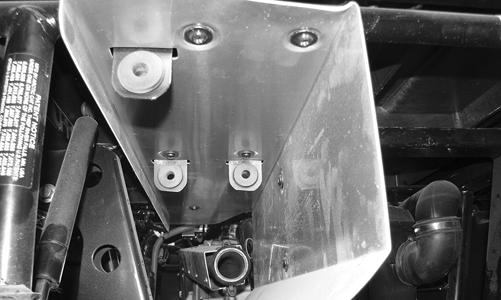
2.Raise the cargo box; then remove the cap screw and nut securing the lower lift support to the frame.
Account for the washer. The cargo box will tilt fully rearward.
HDX257
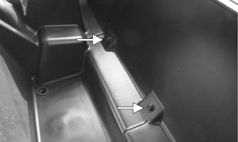
3.Loosen but do not remove the four shoulder cap screws securing the pivot housings to the cargo box.
HDX311
4.Lower the cargo box; then remove the four cap screws (from step 2). 5.With the help of an assistant or an adequate lift, remove the cargo box from the vehicle. Account for four pivot housings. 6.To remove the tilt box actuator (if equipped) from the cargo box, remove the remaining clip and clevis pin.
ROV578
CLEANING AND INSPECTING 1.Clean all cargo box components with soap and water. 2.Inspect the cargo box for cracks, tears, and loose hardware. 3.Inspect the welds of the cargo box frame for cracking or bending. 4.Inspect the cargo box gate latches for smooth operation. INSTALLING 1.With the help of an assistant or an adequate lift, set the cargo box into position on the frame; then position the two upper pivot housings between the cargo box and frame. Lightly grease the pivot housings. 2.Align the holes in the upper pivot housings with the holes in the cargo box; then install the lower pivot housings and secure with the four shoulder cap screws. Tighten to 20 ft-lb. 3.Raise the cargo box; then connect the lift support to the frame, install the cap screw and nut, and tighten the nut securely. 4.Lower the cargo box and lock into position. 5.Install the muffler and heat shield.
Taillight Assembly
REMOVING 1.Remove the cap screws and lock nuts securing the taillight assembly to the ROPS tube. 2.Disconnect the wire connector; then remove the socket assembly and remove the bulb. INSPECTING 1.Inspect wiring harness, three-prong connector, lens, base, cap screws, and socket for damage. 2.Inspect all wires for corroding, pinching, and cracking. 3.Inspect the bulb for wattage, voltage, and proper operation.
INSTALLING 1.Install the new bulb in the socket and place the socket assembly into the taillight housing. Twist clockwise to lock. 2.Connect the wire connector; then install on the
ROPS tube and secure with two cap screws and lock nuts. Tighten securely.
Seat
REMOVING/INSTALLING 1.To remove the seat, raise the front of the seat and slide it forward. 2.To install the seat, slide the rear of the seat into the seat retainers and push down firmly on the front of seat.
Troubleshooting
Problem: Handling too heavy or stiff Condition
Remedy
1. Front wheel alignment incorrect 2. Steering shaft binding 3. Tire inflation pressure incorrect 4. Tie rod ends seizing 5. U-joints seized
Problem: Steering oscillation Condition
1.Adjust alignment 2.Lubricate/replace steering shaft 3.Adjust pressure 4.Replace tie rod ends 5.Replace U-joints
Remedy
1. Tires inflated unequally 2. Wheel(s) bent 3. Wheel hub studs loose - missing 4. Wheel hub bearing worn - damaged 5. Tie rod ends worn - loose 6. Tires defective - incorrect 7. A-arm bushings damaged 8. Bolts - nuts (frame) loose 1.Adjust pressure 2.Replace wheel(s) 3.Tighten - replace wheel studs 4.Replace bearing 5.Replace - tighten tie rod ends 6.Replace tires 7.Replace bushings 8.Tighten bolts - nuts
Problem: Steering pulling to one side Condition Remedy
1. Tires inflated unequally 1.Adjust pressure 2. Front wheel alignment incorrect 2.Adjust alignment 3. Wheel hub bearings worn - broken 3.Replace bearings 4. Frame distorted 4.Repair - replace frame 5. Shock absorber defective 5.Replace shock absorber
Problem: Steering impaired Condition Remedy
1. Tire pressure too high 1.Adjust pressure 2. Steering linkage worn 2.Replace linkage 3. Cap screws (suspension system) loose 3.Tighten cap screws
Problem: Tire wear rapid or uneven Condition Remedy
1. Wheel hub bearings worn - loose 1.Replace bearings 2. Front wheel alignment incorrect 2.Adjust alignment
Problem: Steering noise Condition Remedy
1. Caps screws - nuts loose 1.Tighten cap screws - nuts 2. Wheel hub bearings broken - damaged 2.Replace bearings 3. Lubrication inadequate 3.Lubricate appropriate components
Problem: Rear wheel oscillation Condition Remedy
1. Rear wheel hub bearings worn - loose 1.Replace bearings 2. Tires defective - incorrect 2.Replace tires 3. Wheel rim distorted 3.Replace rim 4. Wheel hub cap screws loose 4.Tighten cap screws 5. Rear suspension arm-related bushing worn 5.Replace bushing 6. Rear shock absorber damaged 6.Replace shock absorber 7. Rear suspension arm nut loose 7.Tighten nut