12 minute read
AUXILIARY A/C BLOWER MOTOR ASSEMBLY PAGE

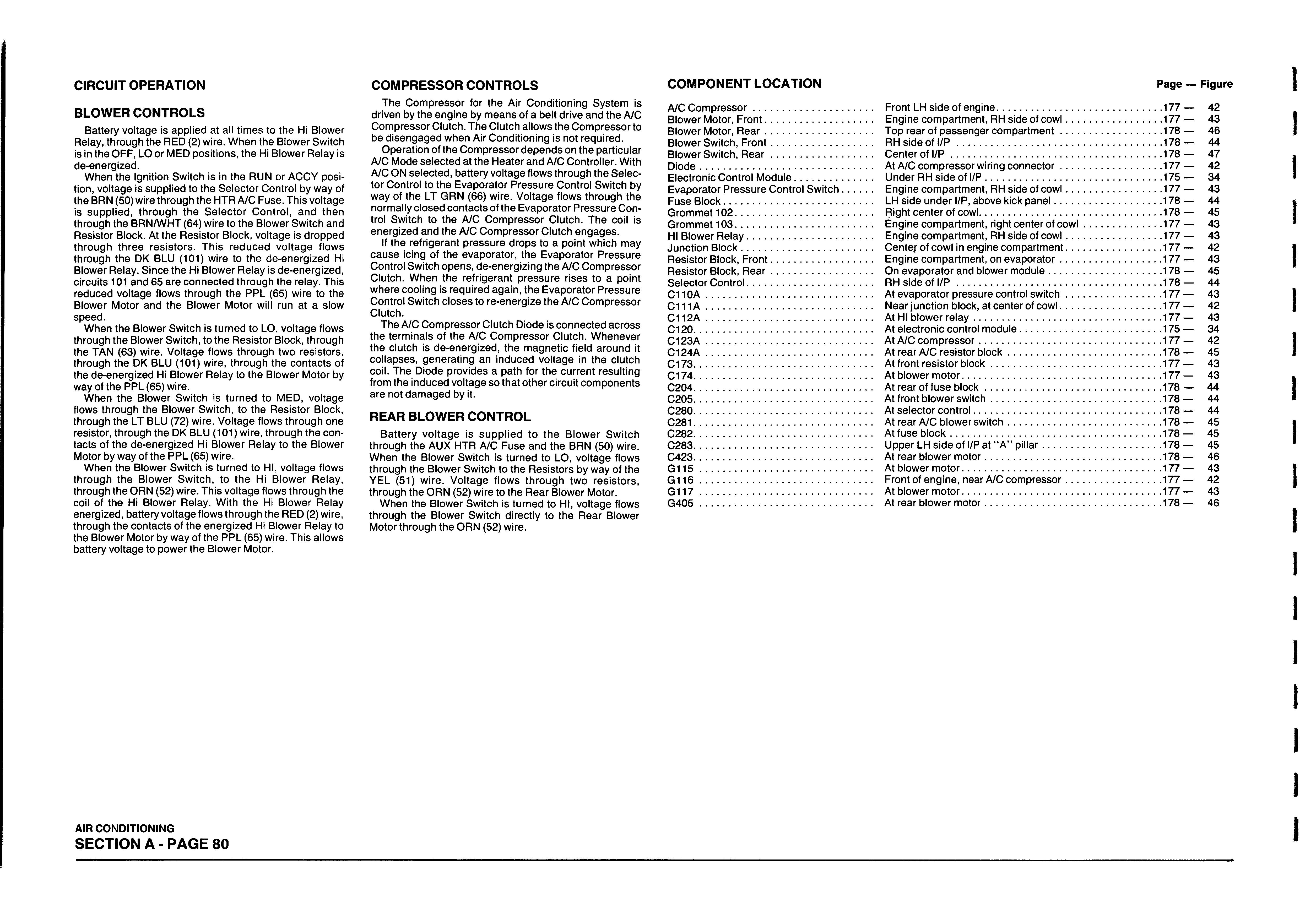
CIRCUIT OPERATION
BLOWER CONTROLS
Battery voltage is applied at all times to the Hi Blower Relay, through the RED (2) wire. When the Blower Switch is in the OFF, LO or MED positions, the Hi Blower Relay is de-energized.
When the Ignition Switch is in the RUN or ACCY position, voltage is supplied to the Selector Control by way of the BRN (50) wire through the HTR A/C Fuse. This voltage is supplied, through the Selector Control, and then through the BRN/WHT (64) wire to the Blower Switch and Resistor Block. At the Resistor Block, voltage is dropped through three resistors. This reduced voltage flows through the DK BLU (101) wire to the de-energized Hi Blower Relay. Since the Hi Blower Relay is de-energized, circuits 101 and 65 are connected through the relay. This reduced voltage flows through the PPL (65) wire to the Blower Motor and the Blower Motor will run at a slow speed.
When the Blower Switch is turned to LO, voltage flows through the Blower Switch, to the Resistor Block, through the TAN (63) wire. Voltage flows through two resistors, through the DK BLU (101) wire, through the contacts of the de-energized Hi Blower Relay to the Blower Motor by way of the PPL (65) wire.
When the Blower Switch is turned to MED, voltage flows through the Blower Switch, to the Resistor Block, through the LT BLU (72) wire. Voltage flows through one resistor, through the DK BLU (101) wire, through the contacts of the de-energized Hi Blower Relay to the Blower Motor by way of the PPL (65) wire.
When the Blower Switch is turned to HI, voltage flows through the Blower Switch, to the Hi Blower Relay, through the ORN (52) wire. This voltage flows through the coil of the Hi Blower Relay. With the Hi Blower Relay energized, battery voltage flows through the RED (2) wire, through the contacts of the energized Hi Blower Relay to the Blower Motor by way of the PPL (65) wire. This allows battery voltage to power the Blower Motor.
The Compressor for the Air Conditioning System is driven by the engine by means of a belt drive and the A/C Compressor Clutch. The Clutch allows the Compressor to be disengaged when Air Conditioning is not required.
Operation of the Compressor depends on the particular A/C Mode selected at the Heater and A/C Controller. With A/C ON selected, battery voltage flows through the Selector Control to the Evaporator Pressure Control Switch by way of the LT GRN (66) wire. Voltage flows through the normally closed contacts of the Evaporator Pressure Control Switch to the A/C Compressor Clutch. The coil is energized and the A/C Compressor Clutch engages.
If the refrigerant pressure drops to a point which may cause icing of the evaporator, the Evaporator Pressure Control Switch opens, de-energizing the A/C Compressor Clutch. When the refrigerant pressure rises to a point where cooling is required again, the Evaporator Pressure Control Switch closes to re-energize the A/C Compressor Clutch.
The A/C Compressor Clutch Diode is connected across the terminals of the A/C Compressor Clutch. Whenever the clutch is de-energized, the magnetic field around it collapses, generating an induced voltage in the clutch coil. The Diode provides a path for the current resulting from the induced voltage so that other circuit components are not damaged by it.
COMPRESSOR CONTROLS
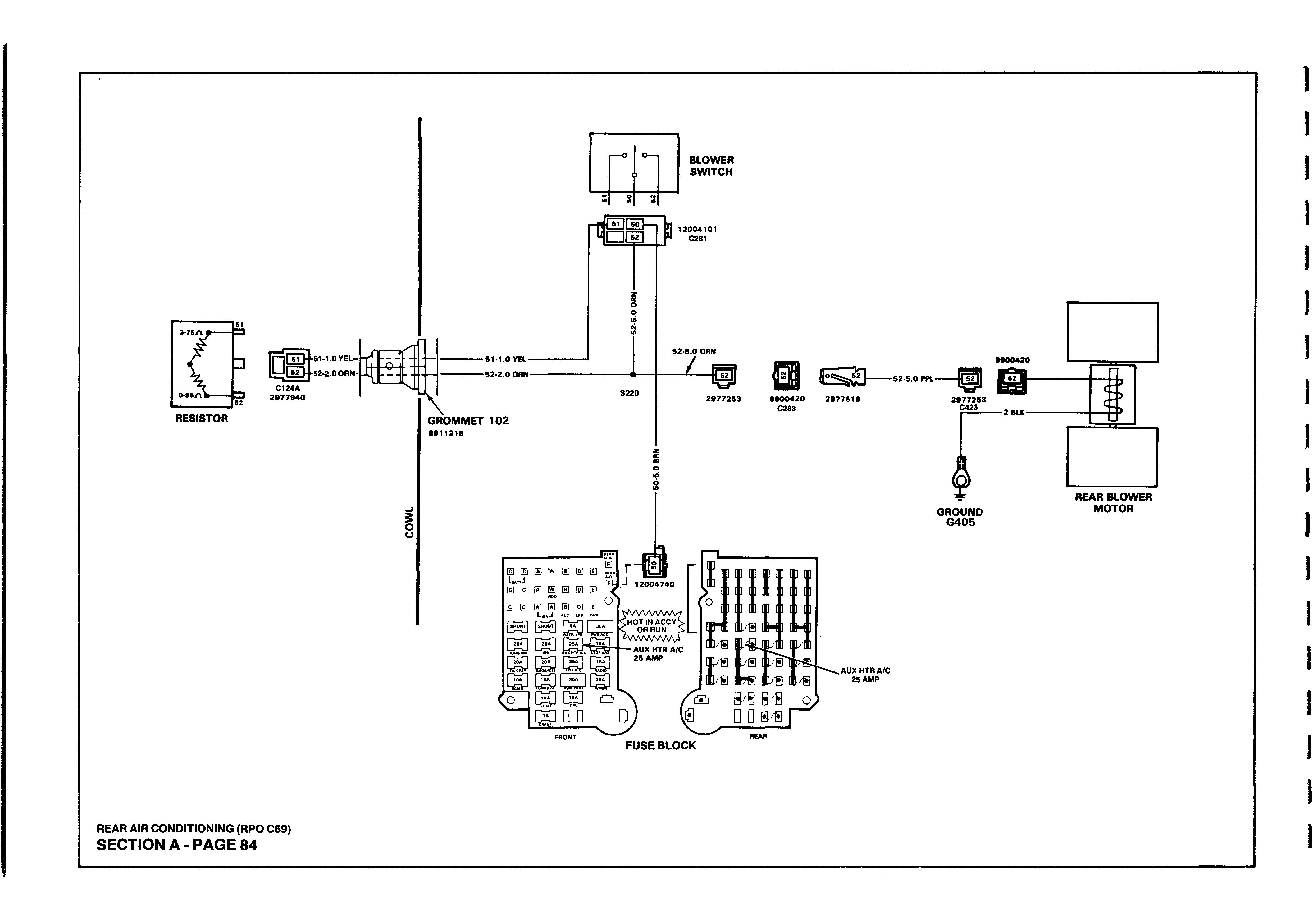
REAR BLOWER CONTROL
Battery voltage is supplied to the Blower Switch through the AUX HTR A/C Fuse and the BRN (50) wire. When the Blower Switch is turned to LO, voltage flows through the Blower Switch to the Resistors by way of the YEL (51) wire. Voltage flows through two resistors, through the ORN (52) wire to the Rear Blower Motor.
When the Blower Switch is turned to HI, voltage flows through the Blower Switch directly to the Rear Blower Motor through the ORN (52) wire.
COMPONENT LOCATION
Page — Figure
A/C C o m p re sso r....................................... .. Front LH side of engine........................................... ...............177 — 42 Blower Motor, F ro n t................................... . . Engine compartment, RH side of c o w l................. ...............177 — 43 Blower Motor, R e a r................................... .. Top rear of passenger com partm ent................... ...............178 — 46 Blower Switch, F ro n t................................ .. RH side of l / P ......................................................... ...............178 — 44 Blower Switch, R e a r ................................. .. Center of l / P ........................................................... ...............178 — 47 D io d e.......................................................... . . At A/C compressor wiring co n n e cto r................... ...............177 — 42 Electronic Control M odule........................ .. Under RH side of l/P ............................................... ...............175 — 34 Evaporator Pressure Control Switch . . Engine compartment, RH side of c o w l................. ...............177 — 43 Fuse B lo ck.................................................. LH side under l/P, above kick p a n e l..................... ...............178 — 44 Grommet 102.............................................. Right center of cowl................................................. ...............178 — 45 Grommet 103.............................................. Engine compartment, right center of c o w l........... ...............177 — 43 HI Blower R elay......................................... . . Engine compartment, RH side of c o w l................. ...............177 — 43 Junction B lo c k........................................... Center of cowl in engine compartment................. ...............177 — 42 Resistor Block, F ro n t................................. Engine compartment, on evaporator................... ...............177 — 43 Resistor Block, R e a r................................. On evaporator and blower m odule........................ ...............178 — 45 Selector C ontrol......................................... . . RH side of l / P ......................................................... ...............178 — 44 C110A ........................................................ At evaporator pressure control s w itc h................. ...............177 — 43 C111A ........................................................ Near junction block, at center of cow l................... ...............177 — 42 C112A ........................................................ At HI blower re la y ................................................... ...............177 — 43 C120............................................................. At electronic control m odule.................................. ...............175 — 34 C123A ........................................................ . . At A/C compressor ................................................. ...............177 — 42 C 1 2 4 A........................................................ . . At rear A/C resistor b lo c k ...................................... ...............178 — 45 C173............................................................. At front resistor b lo c k ............................................. ...............177 — 43 C174............................................................. . . At blower m otor....................................................... ...............177 — 43 C204............................................................. At rear of fuse b lo c k ............................................... ...............178 — 44 C205............................................................. At front blower s w itc h ............................................. ...............178 — 44 C280............................................................. At selector co n tro l................................................... ...............178 — 44 C281............................................................. At rear A/C blower s w itc h...................................... ...............178 — 45 C282............................................................. At fuse b lo c k........................................................... ...............178 — 45 C283............................................................. Upper LH side of l/P at “ A ” p illa r.......................... ...............178 — 45 C423............................................................. At rear blower m o to r............................................... ...............178 — 46 G 1 1 5.......................................................... At blower m otor....................................................... ...............177 — 43 G 1 1 6.......................................................... Front of engine, near A/C com pressor................. ...............177 — 42 G 1 1 7.......................................................... At blower m otor....................................................... ...............177 — 43 G405 .......................................................... At rear blower m o to r............................................... ...............178 — 46
AIR CONDITIONING SECTION A - PAGE 80
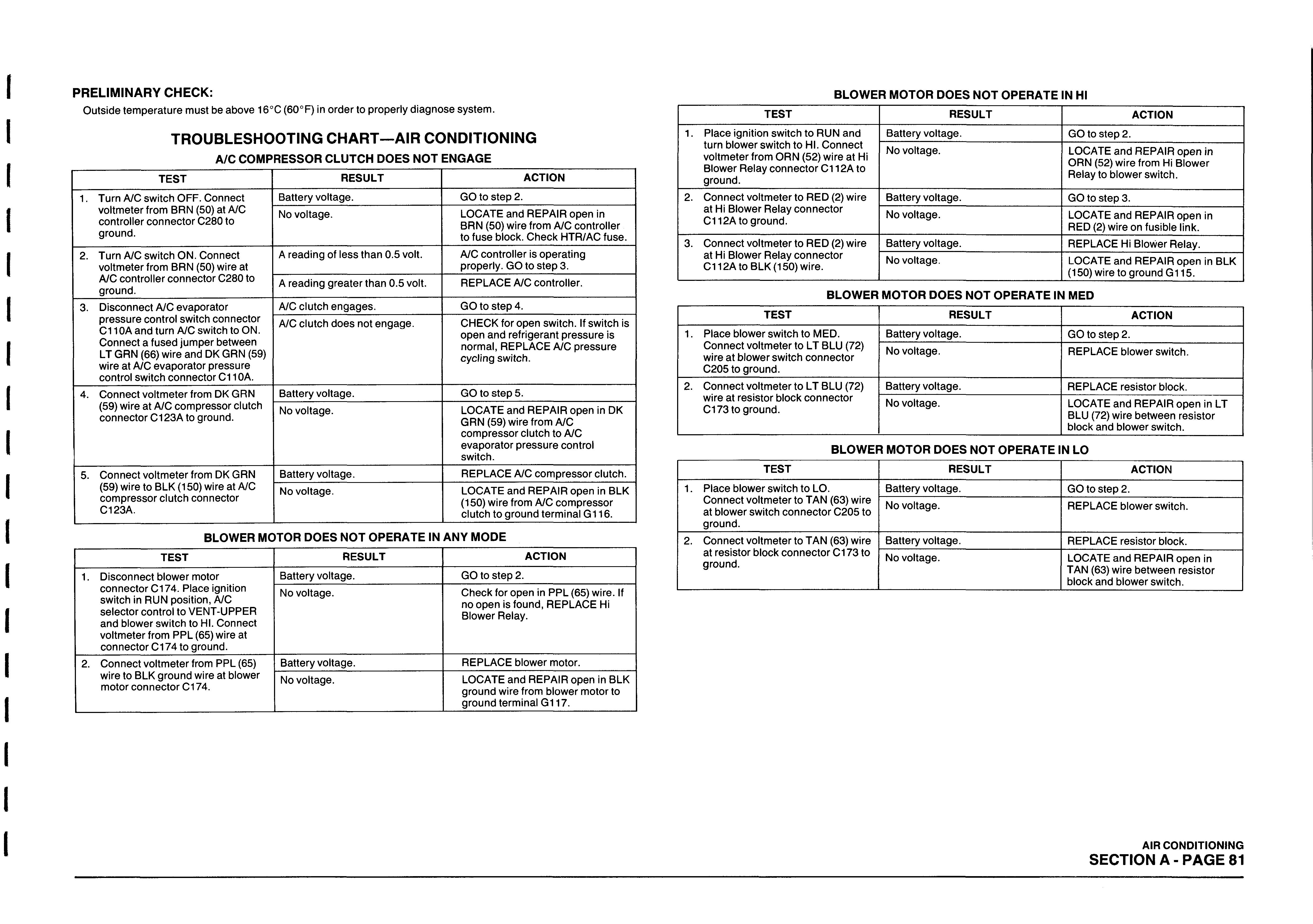
PRELIMINARY CHECK:
Outside temperature must be above 16°C (60°F) in order to properly diagnose system.
TROUBLESHOOTING CHART—AIR CONDITIONING
A/C COMPRESSOR CLUTCH DOES NOT ENGAGE
TEST
1. Turn A/C switch OFF. Connect voltmeter from BRN (50) at A/C controller connector C280 to ground.
2. Turn A/C switch ON. Connect voltmeter from BRN (50) wire at
A/C controller connector C280 to ground. 3. Disconnect A/C evaporator pressure control switch connector
C110A and turn A/C switch to ON.
Connect a fused jumper between
LT GRN (66) wire and DK GRN (59) wire at A/C evaporator pressure control switch connector C110A. 4. Connect voltmeter from DK GRN (59) wire at A/C compressor clutch connector C123A to ground.
5. Connect voltmeter from DK GRN (59) wire to BLK (150) wire at A/C compressor clutch connector
C123A.
RESULT ACTION
Battery voltage. No voltage.
GO to step 2. LOCATE and REPAIR open in BRN (50) wire from A/C controller to fuse block. Check HTR/AC fuse. A reading of less than 0.5 volt. A/C controller is operating properly. GO to step 3. A reading greater than 0.5 volt. REPLACE A/C controller.
A/C clutch engages. A/C clutch does not engage. GO to step 4. CHECK for open switch. If switch is open and refrigerant pressure is normal, REPLACE A/C pressure cycling switch.
Battery voltage. No voltage.
Battery voltage. No voltage. GO to step 5. LOCATE and REPAIR open in DK GRN (59) wire from A/C compressor clutch to A/C evaporator pressure control switch. REPLACE A/C compressor clutch. LOCATE and REPAIR open in BLK (150) wire from A/C compressor clutch to ground terminal G116.
BLOWER MOTOR DOES NOT OPERATE IN ANY MODE
TEST
1. Disconnect blower motor connector C174. Place ignition switch in RUN position, A/C selector control to VENT-UPPER and blower switch to HI. Connect voltmeter from PPL (65) wire at connector C174 to ground. 2. Connect voltmeter from PPL (65) wire to BLK ground wire at blower motor connector C174.
RESULT
Battery voltage. No voltage.
Battery voltage. No voltage.
ACTION
GO to step 2. Check for open in PPL (65) wire. If no open is found, REPLACE Hi Blower Relay.
REPLACE blower motor. LOCATE and REPAIR open in BLK ground wire from blower motor to ground terminal G117.
TEST
BLOWER MOTOR DOES NOT OPERATE IN HI
RESULT ACTION
1. Place ignition switch to RUN and turn blower switch to HI. Connect voltmeter from ORN (52) wire at Hi
Blower Relay connector C112A to ground. 2. Connect voltmeter to RED (2) wire at Hi Blower Relay connector
C112A to ground.
3. Connect voltmeter to RED (2) wire at Hi Blower Relay connector
C112A to BLK (150) wire. Battery voltage. No voltage.
Battery voltage. No voltage.
Battery voltage. No voltage. GO to step 2. LOCATE and REPAIR open in ORN (52) wire from Hi Blower Relay to blower switch.
GO to step 3. LOCATE and REPAIR open in RED (2) wire on fusible link. REPLACE Hi Blower Relay. LOCATE and REPAIR open in BLK (150) wire to ground G 115.
BLOWER MOTOR DOES NOT OPERATE IN MED
TEST
1. Place blower switch to MED.
Connect voltmeter to LT BLU (72) wire at blower switch connect or
C205 to ground. 2. Connect voltmeter to LT BLU (72) wire at resistor block connector
C173 to ground.
RESULT
Battery voltage. No voltage.
Battery voltage. No voltage.
ACTION
GO to step 2. REPLACE blower switch.
REPLACE resistor block. LOCATE and REPAIR open in LT BLU (72) wire between resistor block and blower switch.
TEST BLOWER MOTOR DOES NOT OPERATE IN LO
RESULT ACTION
1. Place blower switch to LO.
Connect voltmeter to TAN (63) wire at blower switch connector C205 to ground. 2. Connect voltmeter to TAN (63) wire at resistor block connector C173 to ground. Battery voltage. No voltage.
Battery voltage. No voltage. GO to step 2. REPLACE blower switch.
REPLACE resistor block. LOCATE and REPAIR open in TAN (63) wire between resistor block and blower switch.
AIR CONDITIONING SECTION A - PAGE 81
PRELIMINARY CHECKS:
CHECK condition of AUX HTR A/C fuse. If fuse is blown, LOCATE and REPAIR source of overload, then REPLACE fuse. If fuse is in good condition, use following diagnostic procedures.
BLOWER MOTOR DOES NOT OPERATE AT ALL
TEST
1. Disconnect blower motor connector C423. Place ignition switch in RUN position. Connect a test lamp from PPL (52) wire at blower motor connector C423 to ground. 2. Connect a test lamp from PPL (52) wire to BLK (2) wire at blower motor connector C134.
3. Connect a test lamp from BRN (50) wire at blower switch connector
C281 to ground.
4. Place blower switch in LO or HI.
Connect a test lamp from blower switch connector C281 at wire that applies to position of switch to ground. LO is YEL (51) wire and HI is ORN (52) wire.
RESULT ACTION
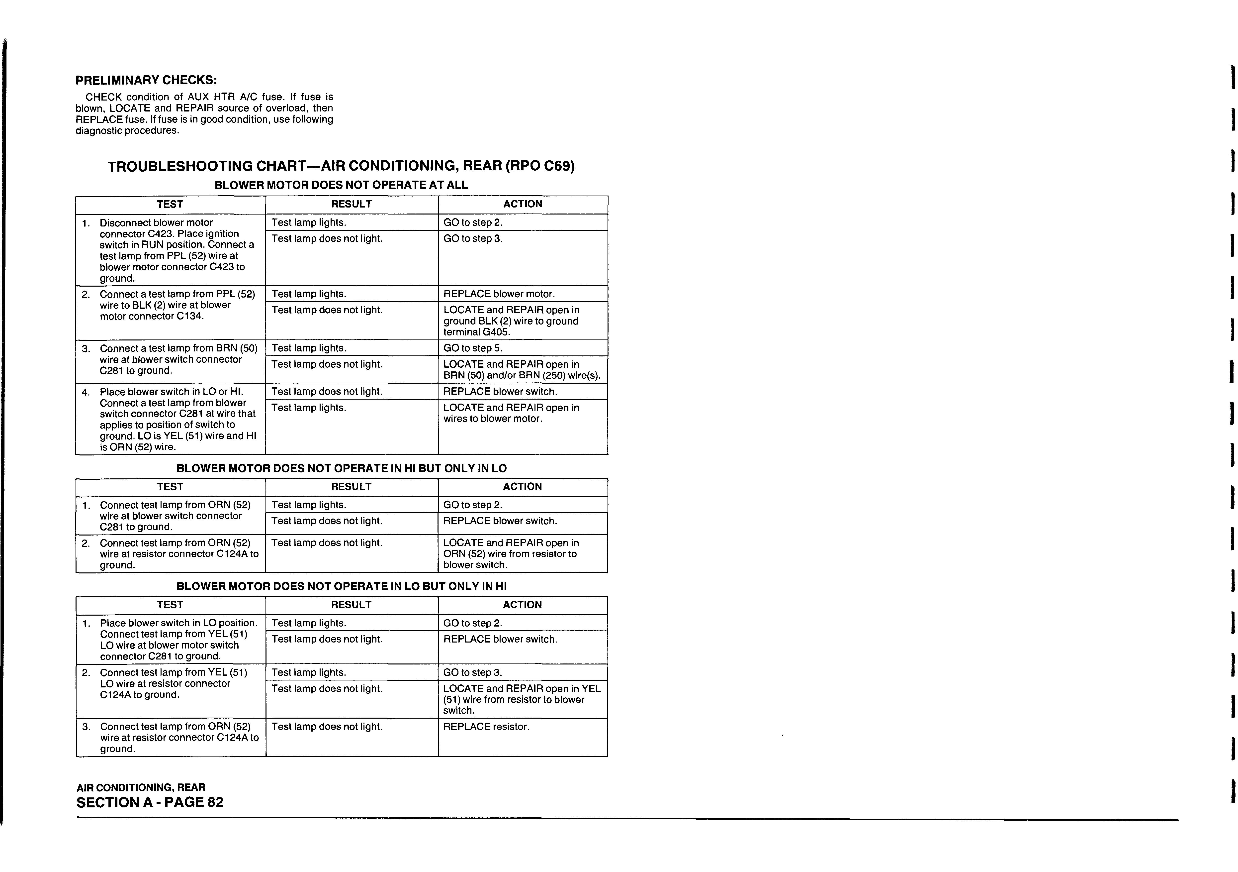
Test lamp lights.
GO to step 2. Test lamp does not light. GO to step 3.
Test lamp lights. REPLACE blower motor. Test lamp does not light. LOCATE and REPAIR open in ground BLK (2) wire to ground terminal G405.
Test lamp lights.
GO to step 5. Test lamp does not light. LOCATE and REPAIR open in BRN (50) and/or BRN (250) wire(s). Test lamp does not light. REPLACE blower switch. Test lamp lights. LOCATE and REPAIR open in wires to blower motor.
TEST RESULT ACTION
1. Connect test lamp from ORN (52) wire at blower switch connector
C281 to ground. 2. Connect test lamp from ORN (52) wire at resistor connector C124A to ground. Test lamp lights. GO to step 2. Test lamp does not light. REPLACE blower switch.
Test lamp does not light. LOCATE and REPAIR open in ORN (52) wire from resistor to blower switch.
TEST RESULT ACTION
1. Place blower switch in LO position.
Connect test lamp from YEL (51)
LO wire at blower motor switch connector C281 to ground. 2. Connect test lamp from YEL (51)
LO wire at resistor connector
C124A to ground.
3. Connect test lamp from ORN (52) wire at resistor connector C124A to ground. Test lamp lights. GO to step 2. Test lamp does not light. REPLACE blower switch.
Test lamp lights. GO to step 3. Test lamp does not light. LOCATE and REPAIR open in YEL (51) wire from resistor to blower switch. Test lamp does not light. REPLACE resistor.
AIR CONDITIONING, REAR SECTION A -PA G E 82
EVAPORATOR C 110A
PRESSURE CONTROL SWITCH
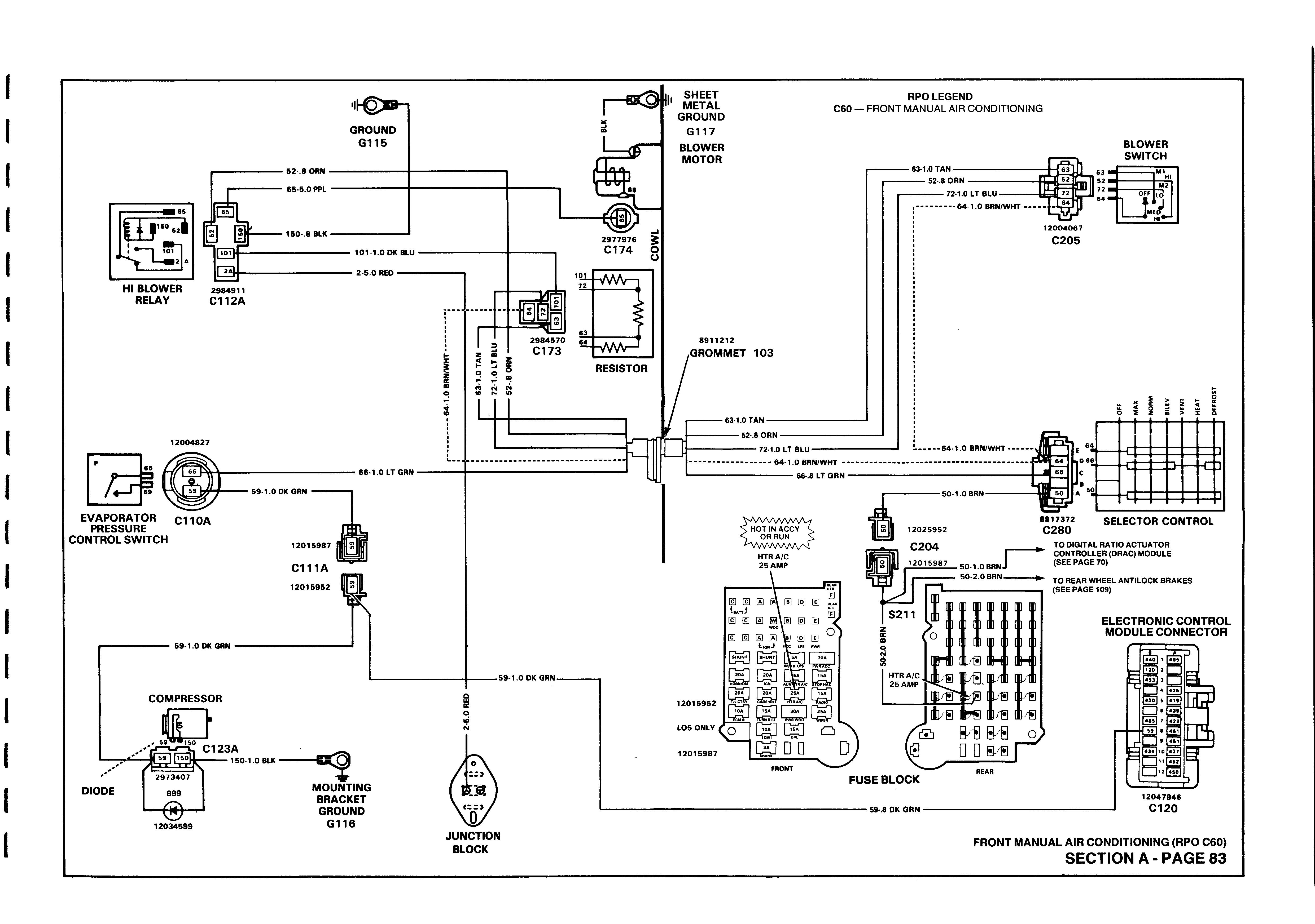
DIODE
12034599
JUNCTION BLOCK
RPO LEGEND C60 — FRONT MANUAL AIR CONDITIONING
BLOWER SWITCH
Ml
HI
OFF LO
‘ U -
M l*""1
r~ L . D
SELECTOR CONTROL
TO DIGITAL RATIO ACTUATOR CONTROLLER (DRAC) MODULE (SEE PAGE 70)
TO REAR WHEEL ANTILOCK BRAKES (SEE PAGE 109)
ELECTRONIC CONTROL MODULE CONNECTOR
12047946 C 120
FRONT MANUAL AIR CONDITIONING (RPO C60) SECTION A - PAGE 83
RESISTOR
51-1.0 YEL-
52-2.0 ORN-
m
■61-1.0 YEL-
-52-2.0 ORN-
GROMMET 102
8911215
§ O O
BLOWER SWITCH
r p Q Dh j C E H u i— IILJUlI
12004101 C281
N 10
S220 52-5.0 ORN
L
