46 minute read
Electrical System

NOTE: Certain components and sensors can be
checked by using the EFI diagnostic system and digital gauge (see EFI Diagnostic System in this section for more information).
TESTING ELECTRICAL COMPONENTS All electrical tests should be made using the CATT II or the Fluke Model 77 Multimeter. The CATT II can return data for certain components which are identified at the beginning of their respective sub-section. If any other type of meter is used, readings may vary due to internal circuitry. When troubleshooting a specific component, always verify first that the fuse(s) are good, that the LED(s) are good, that the connections are clean and tight, that the battery is fully charged, and that all appropriate switches are activated. NOTE: For test accuracy, all tests should be made
at room temperature approximately 68° F.
The electrical connections should be checked periodically for proper function. In case of an electrical failure, check fuses, connections (for tightness, corrosion, damage), and/or bulbs. SPECIAL TOOLS A number of special tools must be available to the technician when performing service procedures in this section. Refer to the current Special Tools Catalog for the appropriate tool description. NOTE: When indicated for use, each special tool
will be identified by its specific name, as shown in the chart below, and capitalized.
Description p/n
Fluke Model 77 Multimeter 0644-559 MaxiClips 0744-041 Timing Light 0644-296
NOTE: Special tools are available from the Arctic
Cat Service Department.
Battery
Component data can be retrieved using the CATT II. Utilize the Sensor Data screen.
NOTE: Preliminary checks may be performed on
this component using the diagnostic mode on the LCD gauge (see EFI Diagnostic System in this section)
After being in service, batteries require regular cleaning and recharging in order to deliver peak performance and maximum service life. The following procedure is recommended for cleaning and maintaining a sealed battery. Always read and follow instructions provided with battery chargers and battery products. NOTE: Refer to all warnings and cautions provided
with the battery or battery maintainer/charger.
Loss of battery charge may be caused by ambient temperature, ignition OFF current draw, corroded terminals, self discharge, frequent start/stops, and short engine run times. Frequent winch usage, snowplowing, extended low RPM operation, short trips, and high amperage accessory usage are also reasons for battery discharge. Maintenance Charging NOTE: Arctic Cat recommends the use of the
CTEK Multi US 800 or the CTEK Multi US 3300 for battery maintenance charging. Maintenance charging is required on all batteries not used for more than two weeks or as required by battery drain.
800E
1.When charging a battery in the vehicle, be sure the ignition switch is in the OFF position. 2.Clean the battery terminals with a solution of baking soda and water. NOTE: The sealing strip should NOT be removed
and NO fluid should be added.
3.Be sure the charger and battery are in a well-ventilated area. Be sure the charger is unplugged from the 110-volt electrical outlet. 4.Connect the red terminal lead from the charger to the positive terminal of the battery; then connect the black terminal lead of the charger to the negative terminal of the battery. NOTE: Optional battery charging adapters are
available from your authorized Arctic Cat dealer to connect directly to your vehicle from the recommended chargers to simplify the maintenance charging process. Check with your authorized Arctic Cat dealer for proper installation of these charging adapter connectors.
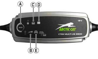
5.Plug the battery charger into a 110-volt electrical outlet. 6.If using the CTEK Multi US 800, there are no further buttons to push. If using the CTEK Multi US 3300, press the Mode button (A) at the left of the charger until the Maintenance Charge Icon (B) at the bottom illuminates. The Normal Charge Indicator (C) should illuminate on the upper portion of the battery charger.
NOTE: The maintainer/charger will charge the bat-
tery to 95% capacity at which time the Maintenance Charge Indicator (D) will illuminate and the maintainer/charger will change to pulse/float maintenance. If the battery falls below 12.9 DC volts, the charger will automatically start again at the first step of the charge sequence.
3300A
NOTE: Not using a battery charger with the proper
float maintenance will damage the battery if connected over extended periods.
Charging NOTE: Arctic Cat recommends the use of the
CTEK Multi US 800 or the CTEK Multi US 3300 for battery maintenance charging.
1.Be sure the battery and terminals have been cleaned with a baking soda and water solution. NOTE: The sealing strip should NOT be removed
and NO fluid should be added.
2.Be sure the charger and battery are in a well-ventilated area. Be sure the charger is unplugged from the 110-volt electrical outlet. 3.Connect the red terminal lead from the charger to the positive terminal of the battery; then connect the black terminal lead of the charger to the negative terminal of the battery. 4.Plug the charger into a 110-volt electrical outlet. 5.By pushing the Mode button (A) on the left side of the charger, select the Normal Charge Icon (E). The
Normal Charge Indicator (C) should illuminate on the upper left portion of the charger. 6.The battery will charge to 95% of its capacity at which time the Maintenance Charge Indicator (D) will illuminate. NOTE: For optimal charge and performance, leave
the charger connected to the battery for a minimum 1 hour after the Maintenance Charge Indicator (D) illuminates. If the battery becomes hot to the touch, stop charging. Resume after it has cooled.
7.Once the battery has reached full charge, unplug the charger from the 110-volt electrical outlet. NOTE: If, after charging, the battery does not perform
to operator expectations, bring the battery to an authorized Arctic Cat dealer for further troubleshooting.
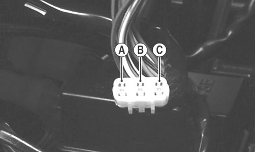
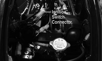
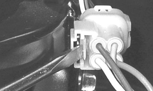
Ignition Switch
The ignition switch harness connects to the switch with a three-pin connector. To access the connector, remove the radiator/electrical access panel.
KC466C
VOLTAGE NOTE: Perform this test on the main harness con-
nector.
1.Set the meter selector to the DC Voltage position. 2.Connect the red meter lead to the red wire; then connect the black meter lead to ground. 3.Meter must show battery voltage. NOTE: If the meter shows no battery voltage, trou-
bleshoot the battery or the main wiring harness.
RESISTANCE NOTE: Perform this test on the switch harness
using the following procedure.
KC276A
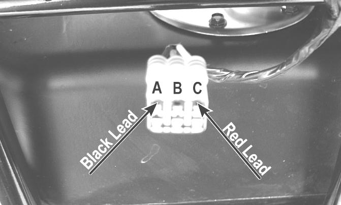
1.Turn the ignition switch to the ON position. 2.Set the meter selector to the OHMS position. 3.Connect either tester lead to pin B; then connect the other tester lead to pin A. 4.The meter must show less than 1 ohm. 5.Turn the ignition switch to the LIGHTS position.
The meter must show less than 1 ohm. 6.Leaving the tester lead on pin B, connect the other tester lead to pin C.
7.The meter must show less than 1 ohm. NOTE: If the meter shows more than 1 ohm of resis-
tance, replace the switch.
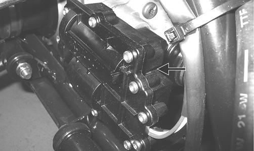
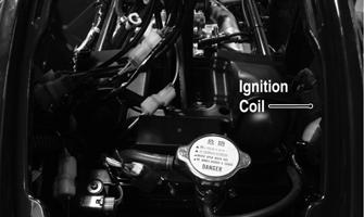
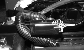
Ignition Coil
The ignition coil is on the frame above the radiator. To access the coil, the radiator/electrical access panel must be removed.
KC466B
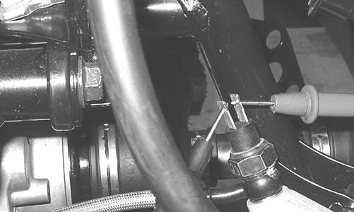
RESISTANCE NOTE: For these tests, the meter selector must be
set to the OHMS position and the primary plug disconnected.
Primary Winding 1.Connect the red tester lead to either terminal; then connect the black tester lead to the other terminal. 2.The meter reading must be within specification. NOTE: Secondary coil resistance checks are not rec-
ommended. An internal diode in the coil prevents accurate secondary resistance measurements.
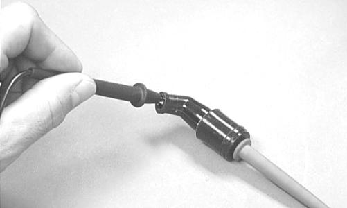
Spark Plug Cap 1.Connect the red tester lead to one end of the cap; then connect the black tester lead to the other end of the cap.
AR603D
2.The meter reading must be within specification. NOTE: If the meter does not read as specified,
replace the spark plug cap.
Ignition Timing
The ignition timing cannot be adjusted; however, verifying ignition timing can aid in troubleshooting other components. To verify ignition timing, use the following procedure. 1.Attach the Timing Light to the spark plug high tension lead; then remove the timing inspection plug from the left-side crankcase cover. 2.Using the Tachometer, start the engine and run at 1500 RPM; ignition timing should be 10° BTDC. 3.Install the timing inspection plug. If ignition timing cannot be verified, the rotor may be damaged, the key may be sheared, the trigger coil bracket may be bent or damaged, or the ECM may be faulty.
Accessory Receptacle/ Connector
NOTE: This test procedure is for either the recepta-
cle or the connector.
VOLTAGE 1.Turn the ignition switch to the ON position; then set the meter selector to the DC Voltage position. 2.Connect the red tester lead to the orange/black wire; then connect the black tester lead to ground. 3.The meter must show battery voltage. 4.To test the rear accessory connector, move the red tester lead to the red/white wire. The meter should read battery voltage. NOTE: If the meter shows no battery voltage, trou-
bleshoot the battery, fuse, receptacle, connector, or the main wiring harness.
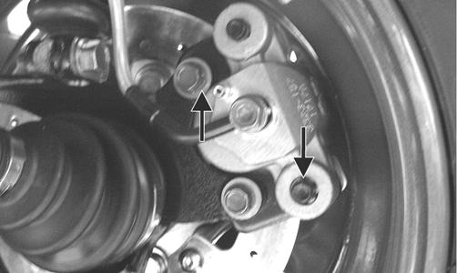
Switches
Component data can be retrieved using the CATT II. Utilize the Sensor Data screen.
VOLTAGE (Brakelight) The front brakelight switch is located in front of the brake master cylinder and is pressure activated by the hand brake or the brake pedal. The switches also activate the start-in-gear feature. NOTE: The ignition switch must be in the ON posi-
tion.
1.Set the meter selector to the DC Voltage position.
2.Connect the red tester to the orange wire; then connect the black tester lead to ground. 3.The meter must show battery voltage. NOTE: If the meter shows no battery voltage, trou-
bleshoot the battery, fuse, or the main wiring harness.
NOTE: If the meter shows battery voltage, the main
wiring harness is good; proceed to test the switch/ component or connector.
RESISTANCE (Brakelight) 1.Remove the spade connectors from the brake switch. 2.Set the meter selector to the OHMS position. 3.Connect the red tester lead to one switch terminal; then connect the black tester lead to the other switch terminal.
KC274
4.When the brake pedal is depressed, the meter must show less than 1 ohm. NOTE: If the meter shows more than 1 ohm of resis-
tance, replace the switch.
RESISTANCE (HI Beam) The connectors are located on the right side of the ATV next to the PDM. To access the connector, the radiator/ electrical access panel must be removed. NOTE: These tests should be made on the switch
side of the connector.
1.Set the meter selector to the OHMS position. 2.Connect one tester lead to the brown/black wire; then connect the other tester lead to the lavender wire. 3.With the dimmer switch in the HI position, the meter must show less than 1 ohm. NOTE: If the meter shows more than 1 ohm of resis-
tance, replace the switch.
RESISTANCE (LO Beam) 1.Connect one tester lead to the brown/black wire; then connect the other tester lead to the white wire. 2.With the dimmer switch in the LO position, the meter must show less than 1 ohm. NOTE: If the meter shows more than 1 ohm of resis-
tance, replace the switch.
RESISTANCE (Engine Stop) 1.Set the meter selector to the OHMS position. 2.Connect the one lead to the brown/lavender wire; then connect the other tester lead to the black/white wire. 3.With the switch in the OFF position, the meter must show an open circuit. 4.With the switch in the RUN position, the meter must show less than 1 ohm. NOTE: If the meter shows more than 1 ohm of resis-
tance, replace the switch.
RESISTANCE (Reverse Override) NOTE: The handlebar control switch connectors
are a six pin and a three pin. Both must be disconnected for this test.
1.Set the meter selector to the OHMS position. 2.Connect one tester lead to one lavender/red wire (three-pin connector); then connect the other tester wire to the green/red wire on the six-pin connector.
The meter must show less than 1 ohm. 3.Depress and hold the reverse override button. The meter must show an open circuit. NOTE: If the meter does not show as specified,
replace the switch.
RESISTANCE (Drive Select)
Component data can be retrieved using the CATT II. Utilize the Sensor Data screen.
The connector is the snap-lock one in front of the steering post. To access the connector, the radiator/electrical access panel cover must be removed. NOTE: Resistance tests should be made with the
connector disconnected and on the switch-side of the connector.
1.Set the meter selector to the OHMS position. 2.Connect the one tester lead to the white/green wire; then connect the other tester lead to the black wire. 3.With the selector switch in the 2WD position, the meter must show an open circuit. 4.With the selector switch in the 4WD position, the meter must show less than 1 ohm. NOTE: If the meter does not show as specified,
replace the front drive select switch.
VOLTAGE (Drive Select) NOTE: The battery must be connected when per-
forming voltage tests.
1.Set the meter selector to the DC Voltage position. 2.Connect the black tester lead to the negative battery terminal.
3.Connect the red tester lead to the white/green wire on the harness side of the connector. 4.Turn the ignition switch to the RUN position. 5.The meter must show battery voltage. NOTE: If the meter shows other than specified,
check the harness, connector, main relay, and battery connections.
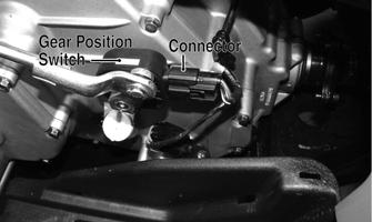
RESISTANCE (Gear Position) The gear position switch is located on the engine/transmission next to the shift arm.
FI525B
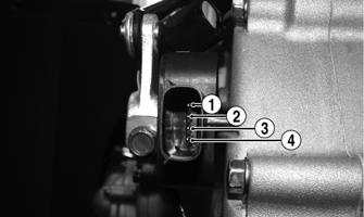
1.Disconnect the gear position switch connector; then using a multimeter, test the switch in each position as follows. Resistance must be less than 1 ohm for all tests.
KC410A
A.Neutral (N)Pins 3 to 4 B.Reverse (R)Pins 3 to 4 and 3 to 2 C.High (H)Pins 3 to 4 and 3 to 1 D.Low (L)Pins 3 to 1 2.Connect the harness to the gear position switch.
This component can be tested using the CATT II. Utilize the Test screen.
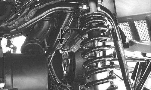
NOTE: To determine if the fan motor is good, con-
nect the blue wire from the fan connector to the positive side of a 12 volt DC power supply; then connect the black wire from the fan connector to the negative side. The fan should operate.
KC270A
! WARNING
Care should be taken to keep clear of the fan blades.
NOTE: Fan motor resistance checks are not recom-
mended. Resistance values change with the motor commutator position.
Front Drive Actuator
NOTE: With the engine stopped and the ignition
switch in the ON position, a momentary “whirring” sound must be noticeable each time the select switch is moved to 2WD and 4WD. Test the switch, main relay, and wiring connections prior to testing the actuator.
VOLTAGE 1.Select the 2WD position on the drive select switch; then disconnect the connector on the actuator wiring harness. 2.With the ignition switch in the OFF position, connect the black tester lead to the black wire in the supply harness; then connect the red tester lead to either orange wire in the supply harness. 3.Turn the ignition switch to the ON position. The meter must show battery voltage. 4.Connect the red tester lead to the second orange wire in the supply harness. The meter must show battery voltage. 5.Connect the red tester lead to the white/green wire in the supply harness. The meter must show battery voltage.
6.Select the 4WD position on the drive select switch; then connect the red tester lead to the white/green wire in the supply harness. The meter must show 0
DC volts. NOTE: The 4WD icon on the LCD should illuminate.
NOTE: If the voltage readings are as specified and
the actuator does not function correctly, replace the actuator (see Drive System).
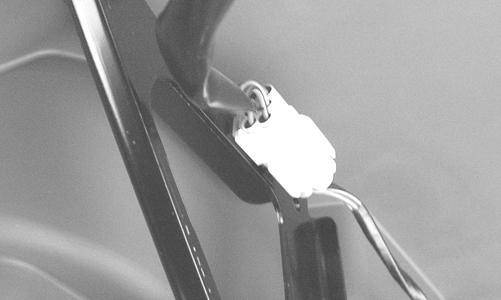
Lights
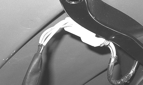
HEADLIGHTS - RUNNING LIGHTS The connectors are the two 4-pin ones snapped onto the front body panel support. To release the connectors from the frame, press the release tab with a small screwdriver.
KC224
KC223
Voltage (Headlights) NOTE: Perform this test on the main harness side of
the connectors. Also, the ignition switch must be in the LIGHTS position.
1.Set the meter selector to the DC Voltage position. 2.Connect the black tester lead to the black wire; then connect the red tester lead to the white wire. 3.With the dimmer switch in the LO position, the meter must show battery voltage. 4.Remove the red tester lead from the white wire and connect to the yellow/black wire. 5.With the dimmer switch in the HI position, the meter must show battery voltage. NOTE: If battery voltage is not shown in any test,
inspect the fuses, battery, main wiring harness, connectors, or the left handlebar switch.
Voltage (Running Lights) 1.Release the wire connector from the frame; then release and separate the connectors. NOTE: Perform this test on the wiring harness side
of the connectors.
2.Connect the black tester lead of the meter to the black wire; then with the tester in the DC Volts position, connect the red tester lead to the white/brown wire. 3.Turn the ignition switch to the LIGHTS position.
The meter must show battery voltage. NOTE: If the meter does not show voltage, inspect
the LIGHTS fuse, battery connections, or troubleshoot the main wiring harness.
TAILLIGHTS - BRAKELIGHTS Voltage (Taillights) NOTE: Perform this test on the main harness side of
the connector. Also, the ignition switch should be in the LIGHTS position.
1.Set the meter selector to the DC Voltage position. 2.Connect the black tester lead to the black wire; then connect the red tester lead to the white/brown wire. 3.The meter must show battery voltage. NOTE: If the meter does not show voltage, inspect
the LIGHTS fuse, wiring harness, connectors, and switches.
Voltage (Brakelights) NOTE: Perform this test on the main harness side of
the connector. Also, the ignition switch should be in the ON position and the brake (either foot pedal or hand lever) must be applied.
1.Set the meter selector to the DC Voltage position. 2.Connect the black tester lead to the black wire; then connect the red tester lead to the red/blue wire. 3.The meter must show battery voltage. NOTE: If the meter does not show voltage, inspect
bulb, the LIGHTS fuse, wiring harness, connectors, and switches.
BACK-UP LIGHTS The connectors are located on the rear frame supports attached by a metal tab. They may be released from the frame by depressing the release with a small screwdriver.
KC279
KC280
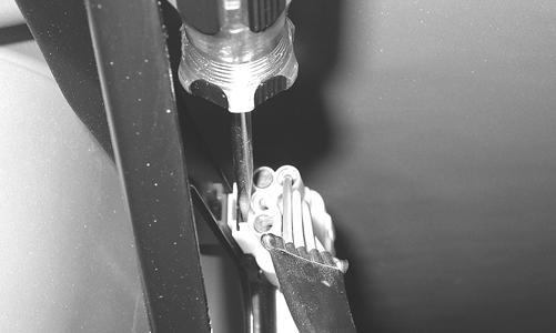
Voltage 1.Release the wire connectors from the frame; then disconnect the connectors. NOTE: Perform this test on the main harness side of
the connectors.
2.Connect the black tester lead to the black wire; then connect the red tester lead to the violet/black wire. 3.Set the tester to DC VOLTS; then turn the ignition switch to the ON position and move the shift lever to the R (reverse) position. The meter must show battery voltage. NOTE: If the meter does not show battery voltage,
use the following procedure to troubleshoot.
4.Remove the black tester lead from the black wire and connect to a suitable ground. A.If the meter shows battery voltage, troubleshoot the gear shift position switch connector or the gear shift position switch. B.If the meter does not show battery voltage, inspect the LIGHTS fuse, BACK-UP relay, ignition switch, or the main wiring harness.
Power Distribution Module (PDM)
A number of fuses and relays are located in the power distribution module in front of the steering post under the radiator/electrical access panel.

KC466A
If there is any type of related electrical system failure, always check the fuses first. NOTE: To remove a fuse, compress the locking tabs
on either end of the PDM cover and lift off; then remove the applicable fuse.
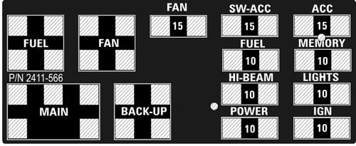
2411-566
CAUTION
Always replace a blown fuse with a fuse of the same type and rating.
RELAYS The relays are identical plug-in type located on the PDM. Relay function can be checked by switching relay positions. The relays are interchangeable. NOTE: The PDM and wiring harness are not a ser-
viceable components and must be replaced as an assembly.
Main Fuse
The electrical system is protected by a 30-amp main fuse incorporated within the starter relay under the battery cover. If all electrical accessories/components fail to operate, always check this main fuse first.
EFI Sensors/Components
FUEL INJECTOR
Component data can be tested using the CATT II. Utilize the Test screen.
Component data can be retrieved using the CATT II. Utilize the Sensor Data screen. Component data can be retrieved using the CATT II. Utilize the Sensor Data screen.
Voltage Remove the connector from the fuel injector. Place the red meter lead to the orange wire and black meter lead to ground. With the ignition switch in the on position the meter must read battery voltage. Resistance With the connector still removed from the injector, place the red meter lead to either terminal; then connect the black tester lead to the other terminal. Reading is typically 12 ohms. NOTE: If voltage is not present, troubleshoot the
battery, connector pins, wiring harness, fuses, or relay. If resistance is not present or largely out of specification, replace the injector.
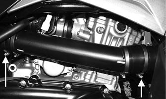
CRANKSHAFT POSITION (CKP) SENSOR Resistance 1.Disconnect the gray two-pin connector on the right side of the engine just above the starter motor. 2.Set the meter selector to the OHMS position. 3.Connect the red tester lead to the green/white wire; then connect the black tester lead to the blue/yellow wire. The meter reading must be within specification. Voltage NOTE: The battery must be at full charge for this
test.
1.Set the meter selector to the DC Voltage position. 2.Connect the red tester lead to the green/white wire; then connect the black tester lead to the blue/yellow wire. 3.Crank the engine over using the electric starter. The meter reading must be within specification. OXYGEN (O2) SENSOR
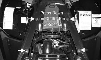
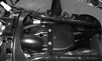
The sensor is located in the exhaust pipe. 1. On the right side of the ATV, unplug the connector.
KC518A
2. On the sensor side of connector, connect the black (negative) test lead to one white wire pin; then connect the red (positive) test lead to the other white wire pin. 3.With the meter in the OHMS position, the reading should be between 6.7-10.1 ohms. NOTE: If the meter does not read as specified,
replace sensor.
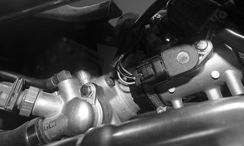
TEMPERATURE/MANIFOLD ABSOLUTE PRESSURE (TMAP) SENSOR
NOTE: Preliminary checks may be performed on
this component using the diagnostic mode on the LCD gauge (see EFI Diagnostic System in this section)
1.Disconnect the sensor connector from the sensor located on top of the throttle body. 2.Select DC Voltage on the tester and turn the ignition switch to the ON position. 3.Connect the black tester lead to the black/pink wire and the red tester lead to the orange/blue wire. The meter should read 4.5-5.5 DC volts. If the meter does not read as specified, check the ECM connector or wiring. 4.Connect the sensor to the harness; then using Maxi-
Clips, connect the red tester lead to the brown/white wire and the black tester lead to the black/pink wire.
With the engine running at idle speed, the meter should read approximately 2.5 DC volts. 5.Connect the red tester lead to the green/red wire.
With the engine at idle and at room temperature (approximately 68° F), the meter should read approximately 2.9 DC volts. NOTE: If the meter does not read as specified,
replace the sensor.
ELECTRIC FUEL PUMP/FUEL LEVEL SENSOR NOTE: Preliminary checks may be performed on
this component using the diagnostic mode on the LCD gauge (see EFI Diagnostic System in this section).
The electric fuel pump and fuel level sensor are not serviceable components. If either component fails, it must be replaced. Testing
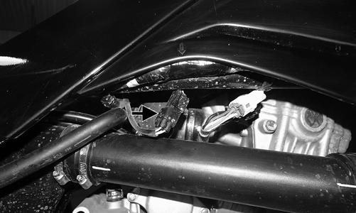
1.Turn the ignition switch ON and listen for a momentary “whirring” sound of the pump building pressure.
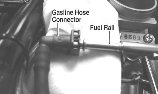
If the sound is heard, no electrical checks are necessary. Turn the ignition switch OFF. 2.Disconnect the gasline hose from the throttle body; then install the Fuel Pressure Test Kit.
! WARNING
Whenever any maintenance or inspection is made on the fuel system during which there may be fuel leakage, there should be no welding, smoking, open flames, etc., in the area.
AT THIS POINT
Prior to removing the electric fuel pump, the following check should be performed to determine that removal is necessary.
! WARNING
Gasoline may be under pressure. Place an absorbent towel under the connector to absorb any gasoline spray when disconnecting.
FI092A
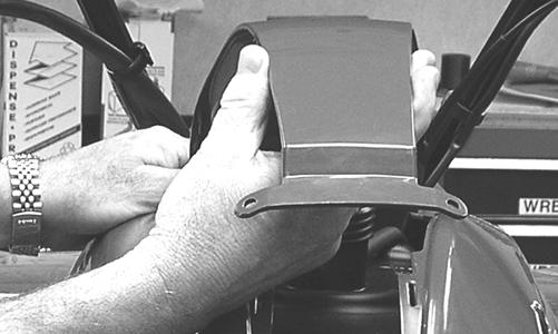
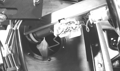
3.Turn the ignition switch to the ON position. The fuel pressure should build until the pump shuts off. Pressure should read 3.0 kg-cm2 (43 psi). 4.If the pump is not running, disconnect the fuel pump/ tank sensor connector located behind the right side panel. 5.Connect a multimeter to the power supply leads with the red tester lead to the red wire and the black tester lead to the black wire; then turn the ignition switch to the ON position. The meter should read battery voltage. If battery voltage is indicated and the fuel pump does not run, replace the pump assembly. If no battery voltage is indicated, check the ECM and the vehicle tilt sensor. Removing 1.Disconnect the negative battery cable from the battery. 2.Remove the side panels and gas tank cover.
KC220
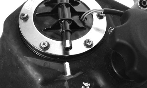
3.Mark the fuel pump and gas tank for proper orientation during assembly; then disconnect the fuel pump/ fuel level sensor connector.
KC423
4.Disconnect the gasline connector from the fuel pump outlet.
5.Remove the screws securing the fuel pump to the gas tank; then make a reference mark on the fuel pump and tank. 6.Lift out the fuel pump assembly and carefully guide the pump and float lever through the opening in the gas tank.
7.Using duct tape or other suitable means, cover the fuel pump opening.
! WARNING
Gasoline may be under pressure. Place an absorbent towel under the connector to absorb any gasoline spray when disconnecting.
! WARNING
Do not turn the ignition switch to the ON position with the hoses removed. Gasoline will be pumped by the electric fuel pump causing a safety hazard.
CAUTION
Take care not to damage the float or float lever or replacement of the entire assembly will be necessary.
If the pump has failed earlier test and must be replaced, proceed to INSTALLING.
1.Inspect the fuel screen and blow clean with low pressure compressed air. 2.Move the float lever and check for free movement.
The float assembly should return to the lower position without force. If not, replace the fuel pump assembly. 3.Test the fuel level sensor by connecting a multimeter (A) to the fuel level sensor leads (B); then select
OHMS. The multimeter should show 5 ohms at full fuel position (C) and 95 ohms at empty fuel position (D).
ATV2116
NOTE: If readings are erratic, clean the resistor
wiper and resistor with clean alcohol and retest. If still not correct, replace the fuel pump assembly.
Installing 1.Mark the new fuel pump with a reference mark in the same location as the removed pump; then place the new gasket on the pump. 2.Remove the material covering the fuel pump opening; then carefully guide the fuel pump into position taking care not to damage the float or float lever.
KX190
3.Rotate the fuel pump until the match marks align; then install the mounting screws and tighten securely using a crisscross pattern. NOTE: It is important to install the fuel pump with
the correct orientation to ensure adequate float lever clearance.
4.Connect the wires and gasline hose; then connect the negative battery cable and turn the ignition switch to the ON position. Note that the fuel pump runs momentarily and the fuel gauge indicates the proper fuel level. 5.With the transmission in neutral and brake lever lock engaged, start the engine and check for normal operation. Check for any fuel leaks. 6.Install the side panels and gas tank cover. ENGINE COOLANT TEMPERATURE (ECT) SENSOR
Component data can be retrieved using the CATT II. Utilize the Sensor Data screen.
NOTE: Preliminary checks may be performed on
this component using the diagnostic mode on the LCD gauge (see EFI Diagnostic System in this section)
1.Connect the meter leads (selector in OHMS position) to the sensor terminals. 2.Suspend the sensor and a thermometer in a container of cooking oil; then heat the oil. NOTE: Neither the sensor nor the thermometer
should be allowed to touch the bottom of the container or inaccurate readings will occur. Use wire holders to suspend the sensor and thermometer.
! WARNING
Wear insulated gloves and safety glasses. Heated oil can cause severe burns.
TEMPERATURE RESISTANCE 20° C (68° F) 2.45k Ohms 50° C (122° F) 800 Ohms 80° C (176° F) 318 Ohms 110° C (230° F) 142 Ohms
3.If the readings are not as indicated, the sensor must be replaced. 4.Install the sensor and tighten securely. 5.Connect the leads. SPEED SENSOR NOTE: Preliminary checks may be performed on
this component using the diagnostic mode on the LCD gauge (see EFI Diagnostic System in this section)
1.Set the meter selector to the DC Voltage position. 2.With appropriate needle adapters on the meter leads, connect the red tester lead to the orange wire; then connect the black tester lead to the ground wire. 3.Turn the ignition switch to the ON position. 4.The meter must show battery voltage. 5.Leave the black tester lead connected; then connect the red tester lead to the pink/white wire.
6.Slowly move the ATV forward or backward; the meter must show 0 and >12 volts alternately. NOTE: If the sensor tests are within specifications,
the speedometer/LCD gauge must be replaced (see Speedometer/LCD Gauge).
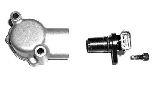
To replace a speed sensor, use the following procedure. 1.Disconnect the three-wire connector from the speed sensor; then remove the cap screw securing the sensor to the sensor housing. 2.Remove the sensor from the sensor housing accounting for an O-ring. 3.Install the new speed sensor into the housing with new O-ring lightly coated with multi-purpose grease; then secure the sensor with the cap screw (threads coated with blue Loctite #242). Tighten securely.
CD071
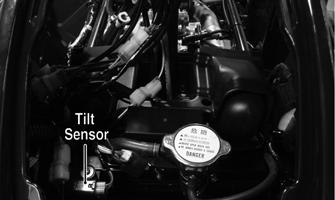
TILT SENSOR The tilt sensor is located above the radiator under the radiator/electrical access panel.
Supply Voltage 1.Disconnect the three-wire connector from the sensor; then select DC Voltage on the multimeter and connect the red tester lead to the orange/blue wire (C) and the black tester lead to the pink/black wire (A).
! WARNING
Incorrect installation of the tilt sensor could cause sudden loss of engine power which could result in loss of vehicle control resulting in injury or death.
CAUTION
Do not drop the tilt sensor as shock can damage the internal mechanism.
CD706A
2.Turn the ignition switch to the ON position. The multimeter should read approximately 5 DC volts. If correct voltage is not indicated, check the main relay and 10-amp ignition fuse, wiring harness, or the ignition switch. 3.Remove the red tester lead and connect to the blue/ brown wire (B). The multimeter should read approximately 0.5 DC volts. If the specified voltage is not indicated, check wire connections at the ECM or substitute another ECM to verify the test. Output Voltage NOTE: Needle adapters or a “break-out” harness
will be required on the multimeter leads as the following tests are made with the sensor connected.
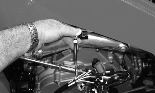
1.Connect the three-wire plug to the sensor; then remove the mounting screws securing the sensor to the frame.
KC466F
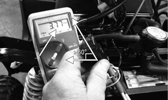
2.Install the needle adapters to the multimeter leads; then select DC Voltage on the multimeter. 3.Connect the red tester lead to the blue/brown wire (B) and the black tester lead to the pink/black wire (A); then turn the ignition switch ON and observe the meter. The meter should read 0.3-1.5 DC volts.
KC416A
4.Tilt the sensor 60° or more to the left and right observing the meter. The meter should read 3.0-8.0
DC volts after approximately one second in the tilted position. If the meter readings are not as specified, the tilt sensor is defective.
KC414A
THROTTLE POSITION SENSOR (TPS)
Component data can be retrieved using the CATT II. Utilize the Sensor Data screen.
NOTE: Preliminary checks may be performed on
this component using the diagnostic mode on the LCD gauge (see EFI Diagnostic System in this section)
Verifying TPS Adjustment Tool Before using the TPS adjustment tool, verify its battery condition. The battery used in the tool is a 9-volt battery. To check battery condition, use a digital volt/ohmmeter set on DC volt scale. Test between the adjustment tool black and red jacks. Insert the red lead of the digital voltmeter into the red jack of the adjustment tool and the black lead of the digital voltmeter into the black jack of the adjustment tool. The green power light of the analyzer should now be illuminated. If voltage is found below 4.9 volts, replace the battery. NOTE: The Test Harness must be plugged into the
analyzer for testing voltage. Always verify battery voltage is at least 4.9 DC volts before testing TPS.
Testing 1.Remove the left-side engine cover; then disconnect the three-wire TPS connector plug.
KC517
NOTE: Prior to testing the TPS, inspect the three-
wire plug connector on the main harness and the three-pin plug on the TPS for contamination, broken pins, and/or corrosion.
NOTE: If the vehicle is in warranty, removing or
adjusting the TPS will void warranty. If the TPS is tested out of specification, the throttle body must be replaced. If the vehicle is out of warranty, the TPS may be adjusted.
2.Connect the TPS Multi-Analyzer Harness connector #8 to the TPS; then connect the harness to the TPS
Analyzer Tool.
FI672
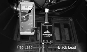
3.Using a multimeter, connect the black tester lead to the black socket (GND) on the analyzer and the red tester lead to the white socket (VAR); then select the
DC Voltage position. With the vehicle off, the gauge should read 0.66-0.70 and at Wide-Open Throttle it should read up to approximately 3.88.
FI673A
Adjusting 1.Loosen the screw securing the TPS to the throttle body.
2.Adjust the TPS until the correct reading is obtained; then tighten the screw securely. Open and close the throttle and determine the reading at idle the correct voltage. Readjust as necessary. 3.Tighten the mounting screw securely. NOTE: If the throttle body, ECM, TPS, or ISC are
replaced, the EFI system must be synchronized. Use the following procedure.
1.With the key off, depress throttle lever to Wide Open
Throttle (WOT). 2.Place the ignition key in the ON position and wait for 10 seconds. 3.Release the throttle lever and wait an additional 10 seconds.
RPM Limiter
Component data can be retrieved using the CATT II. Utilize the Sensor Data screen.
NOTE: The ATV is equipped with an ECM that
cuts fuel delivery when maximum RPM is approached. When the RPM limiter is activated, it could be misinterpreted as a high-speed misfire.
Gear Park Neutral Reverse High/Low Fail-Safe Mode Incorrect ECU/ Gauge (P0630)
Warranty Registration (U1001)
2WD 4WD 4000 4WD Lock 2250 6500 2WD Override 5500 4WD Override Differential-Lock Override 7000 7650 4000 6650 4500
Stator Coil
VOLTAGE (AC Generator Coil - No Load) The connector is the black three-pin one on the right side of the engine just above the starter motor. 1.Set the meter selector to the AC Voltage position. 2.Test between the three yellow wires for a total of three tests. 3.With the engine running at the specified RPM, all wire tests must show 60 AC volts.
CAUTION
Do not run the engine at high RPM for more than 10 seconds.
NOTE: If both AC Generator coil tests failed, check
all connections, etc., and test again. If resistance is present but no voltage is present, check the rotor.
RESISTANCE (AC Generator Coil) 1.Set the meter selector to OHMS position. 2.Test between the three yellow wires for a total of three tests. 3.The meter reading must be within specification.
Regulator/Rectifier
The regulator/rectifier is located under the radiator/electrical access panel.
TESTING 1.Start engine and warm up to normal operating temperatures; then connect a multimeter to the battery as follows. 2.Select the DC Voltage position; then connect the red tester lead to the positive battery post and the black tester lead to the negative battery post. 3.Start the engine and slowly increase RPM. The voltage should increase with the engine RPM to a maximum of 15.5 DC volts.
CAUTION
Do not run the engine at high RPM for more than 10 seconds.
NOTE: If voltage rises above 15.5 DC volts, the reg-
ulator is faulty or a battery connection is loose or corroded. Clean and tighten battery connections or replace the regulator/rectifier. If voltage does not rise, check Voltage (Charging Coil - No Load) in this section. If charging coil voltage is normal, replace the regulator/rectifier.
Starter Motor
NOTE: The starter motor is a non-serviceable com-
ponent. If the following test does not result as specified, the starter motor must be replaced.
TESTING VOLTAGE Perform this test on the starter motor positive terminal. To access the terminal, slide the boot away.
NOTE: The ignition switch must be in the ON posi-
tion, the engine stop switch in the RUN position, and the shift lever in the NEUTRAL position.
1.Set the meter selector to the DC Voltage position. 2.Connect the red tester lead to the starter terminal; then connect the black tester lead to ground. 3.With the starter button depressed, the meter must show approximately 10.0 DC volts and the starter motor should operate.
AR607D
NOTE: If the meter showed correct voltage but the
starter motor did not operate or operated slowly, the starter motor may be defective or there may be a mechanical failure preventing the starter motor from operating.
NOTE: If the meter showed no voltage, inspect ground
connections, starter motor lead, battery voltage (at the battery), starter motor relay, or the neutral start relay.
REMOVING 1.Disconnect the battery.
CAUTION
Always disconnect the negative battery cable from the battery first; then disconnect the positive cable.
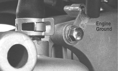
2.Remove the nut securing the positive cable to the starter motor; then remove the cable from the starter motor. 3.Remove the two cap screws securing the starter motor to the crankcase; then remove the starter motor. Account for an O-ring. INSTALLING 1.Apply a small amount of grease to the O-ring seal on the starter motor; then install the starter into the crankcase. Secure with two cap screws making sure the engine ground is secured by the rear cap screws.
Tighten to 8 ft-lb.
KC201A
2.Secure the positive cable to the starter motor with the nut. Tighten to 8 ft-lb. 3.Connect the battery.
Starter Relay
1.Remove the battery case access cover; then using the multimeter set to the DC Voltage position, check the relay as follows. 2.Connect the red tester lead to the positive battery terminal; then connect the black tester lead to the starter cable connection on the starter relay. The meter must show battery voltage. NOTE: Make sure that the ignition switch is in the
ON position, transmission in neutral, brake lock released, and the engine stop switch in the RUN position.
3.Depress the starter button while observing the multimeter. The multimeter should drop to 0 volts, a
“click” should be heard from the relay, and the starter motor should run. NOTE: If a “click” is heard and any voltage is indi-
cated by the multimeter, replace the starter relay. If no “click” is heard and the multimeter continues to indicate battery voltage, test the neutral start relay.
Electronic Control Module (ECM)
The electronic control module (ECM) is located above the radiator under the radiator/electrical access panel. NOTE: The ECM is not a serviceable component. If
the unit is defective, it must be replaced.
The ECM is rarely the cause for electrical problems; however, if the ECM is suspected, substitute another ECM of the same part number to verify the suspected one is defective. Diagnostic Trouble Codes (DTC) can be cleared by following the procedures located in the Diagnostic Trouble Codes (DTC) sub-section in this section.
NOTE: If the throttle body, ECM, TPS, or ISC are
replaced, the EFI system must be synchronized. Use the following procedure.
1.With the key off, depress throttle lever to Wide Open
Throttle (WOT). 2.Place the ignition key in the ON position and wait for 10 seconds. 3.Release the throttle lever and wait an additional 10 seconds. 4.Turn the key to the OFF position and allow the gauge to shut off.
EFI Diagnostic System
DIGITAL GAUGE The digital gauge can be used as a diagnostic tool for many of the DTC’s displayed. To place the gauge into the diagnostic mode, use the following procedure. 1.Turn the ignition switch ON. 2.Depress and hold both Mode and Set buttons together for approximately 10 seconds after which the letters “dIAg” will appear on the LCD momentarily followed by COOL.
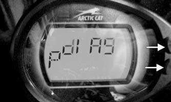
EFI002A
NOTE: The display on the gauge will display in SAE
(speedometer in MPH mode) or Metric (speedometer in km/h mode), For example to read temperature in degrees Celsius, select km/h mode on the gauge or to read Fahrenheit, select MPH mode.
3.Cycle the display by depressing either the Set or
Mode button to step to the desired function.
EFI004
NOTE: The gauge can be utilized dynamically
(engine running/vehicle moving) or statically (engine/ vehicle stopped).
Examples of Static checks: Battery voltage, fuel gauge/ sensor, and TPS (0% @ closed throttle, 95-100% @ WOT).
EFI007
Examples of Dynamic checks: Battery charging, coolant temperature including fans ON/OFF (see below), MAP/ IAT, tachometer, and speedometer signal.
EFI003
EFI 003
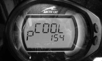
Display: Engine coolant temperature as measured by the ECT sensor. DTC: P0116, P0117, P0118, P0119 Usage: Monitor coolant temperature to verify the following. 1.ECT sensor signal 2.High Temperature indicator (on @ 230 degrees F). 3.Thermostat opening @ approximately 180 degrees F, indicated by a momentary drop or pause in the rising temperature reading. 4.Fan ON @ 194 degrees F, OFF @ 185 degrees F. A. fan motor B. fan relay C. fan fuse D. wiring connections 5.High Temperature Rev Limiter 5000 RPM @ 230 degrees F. Fuel Sensor (FUEL) Diagnostic Mode
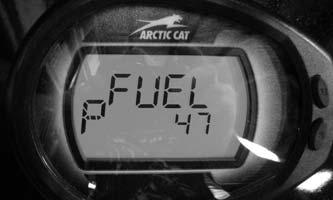
EFI010
Display: Fuel level signal from the fuel level sensor (measured in ohms). DTC: C1400 Usage: Check output of the fuel level sensor 1.Full fuel is indicated by a reading of 86-100 ohms 2. Empty is indicated by a reading of 0-5 ohms.
EFI009
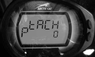
Display: Engine RPM DTC: P0336, P0337, P0339 Usage: Verify engine speed signal from the following. 1.CKP (crankshaft position) sensor to ECM 2. ECM (CAN) signal to gauge (tachometer) 3. ECM (CAN) signal to EPS Speed (SPd) Diagnostic Mode
EFI008
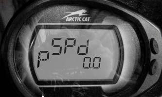
Display: vehicle speed signal. DTC: P0500 Usage: verify speedometer sensor signal from the following. 1.Speed sensor to ECM. 2.ECM (CAN) signal to gauge (speedometer/odometer). 3.ECM (CAN) signal to EPS unit. TPS (tPS) Diagnostic Mode
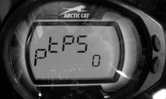
Display: % of TPS (0% closed, 95-100% WOT). DTC: P0121, P0122, P0123 Usage: Verify TPS signal and adjust throttle cable. MAP (bArO) Diagnostic Mode
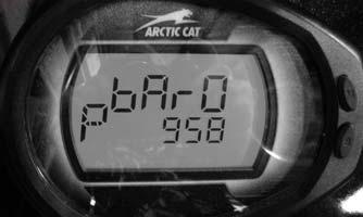
EFI006
Display: MAP in millibars (1013 millibar = 29.92 in. mercury). DTC: P0107, P0108 Usage: Verify barometric pressure signal correct. NOTE: Local barometric pressure is given in in./Hg
(Inches of Mercury). 34 millibars are equal to 1 inch of mercury. Example: (Gauge reading in the BARO mode = 974 millibars, thus 974/34 = 28.64 in./Hg). Second example: (Local barometer reading is 29.87 in./Hg, therefore 29.87 X 34 = 1015 millibars) The gauge should be reading very close to 1015.
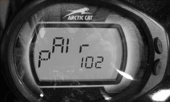
Inlet Air Temperature (AIr) Diagnostic Mode
EFI005
Display: Inlet air temperature in Fahrenheit or Celsius. DTC: P0112, P0113, P0114 Usage: Verify correct output of IAT sensor. NOTE: After engine has been running, IAT read-
ings will be higher than outside air temperature due to engine and engine compartment heat as well as intake manifold heating.
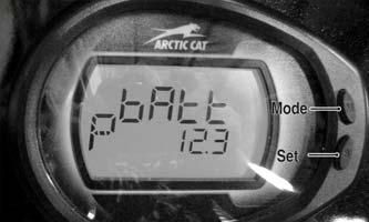
Battery (bAtt) Diagnostic Mode
EFI004
Display: System DC voltage. DTC: P0562, P0563, P2531, P2532 Usage: Verify system voltage under following conditions. 1.Battery voltage with engine and accessories off (>12.2 VDC for fully charged). 2.Battery voltage with engine running (charging = 13.8
VDC or greater). 3.Battery voltage with electrical accessories operating, engine idling (13.5 VDC or greater). 4.Battery voltage starter cranking (10.5-11.5 VDC). DIAGNOSTIC TROUBLE CODES (DTC) If an EFI or related chassis component fails or an out-oftolerance signal is detected by the ECM, a diagnostic trouble code (DTC) will be generated in the ECM and displayed on the LCD. The DTC will be displayed alternately with a wrench icon or malfunction indicator light (MIL). The DTC will continue to flash, until the malfunction is corrected and the code cleared. Code List NOTE: Cycling the ignition (ON, OFF, ON) could
deactivate the DTC until the activating condition reoccurs.
NOTE: Each of the following numerical codes will
have a one-letter prefix of C, P, or U. A “C” prefix denotes a chassis malfunction, a “P” prefix denotes a power train malfunction, and a “U” prefix denotes a loss of communication with the gauge.
NOTE: Normal malfunction codes are cleared from
the LCD when the component is replaced or the malfunction is corrected; however, intermittent codes must be cleared as noted in the code chart.
Code Fault Description Possible Cause Fault Recovery
C0063 Tilt Sensor Circuit High Sensor or interconnect harness shorted to battery power Correct condition* C0064 Tilt Sensor Circuit Low/SG/Open Sensor or interconnect harness open or shorted to chassis ground Correct condition* P0030 O2 Heater Intermittent/Open Heater or interconnect harness is intermittent or open Correct condition* P0031 O2 Heater Low/SG Heater or interconnect harness shorted to chassis ground Correct condition* P0032 O2 Heater High/SP Heater or interconnect harness shorted to battery power Correct condition*
P0107 MAP Sensor Circuit Low/SG/Open Sensor or interconnect harness shorted to chassis ground Correct condition* P0108 MAP Sensor Circuit High/SP Sensor or interconnect harness shorted to battery power Correct condition* P0112 Intake Air Temp Sensor Circuit Low/SG Sensor or interconnect harness shorted to chassis ground Correct condition* P0113 Intake Air Temp Sensor Circuit High/Open Sensor or interconnect harness open or shorted to battery power Correct condition* P0114 Intake Air Temp Sensor Circuit Intermittent Sensor or interconnect harness intermittent Correct condition* P0116 ECT Sensor Circuit Range/Performance Sensor producing an out-of-range voltage Correct condition* P0117 ECT Sensor Circuit Low/SG Sensor or interconnect harness shorted to chassis ground Correct condition* P0118 ECT Sensor Circuit High/Open/SP Sensor or interconnect harness open or shorted to battery power Correct condition* P0119 ECT Sensor Circuit Intermittent Sensor or interconnect harness intermittent Correct condition* P0121 TPS Range/Performance Sensor producing an out-of-range voltage Correct condition* P0122 TPS Circuit Low/SG Sensor or interconnect harness shorted to chassis ground Correct condition* P0123 TPS Circuit High Sensor or interconnect harness open or shorted to battery power Correct condition* P0130 O2 Sensor Intermittent/Open Sensor or interconnect harness intermittent or open Correct condition* P0131 O2 Sensor Low/SG or Air-Leak Sensor or interconnect harness shorted to chassis ground or an air-leak Correct condition* exists P0132 O2 Sensor High/SP Sensor or interconnect harness shorted to battery power Correct condition* P0171 O2 Feedback Below Minimum Correction Low fuel rail pressure, dirty fuel filter, or dirty injectors Correct condition* P0172 O2 Feedback Exceeds Maximum Correction Excessive fuel rail pressure, MAP or temp sensors out-of-spec Correct condition* P0219 Engine Over-Speed Condition Engine speed (RPM) has exceeded the ECM over-speed setpoint/limit Reduce engine speed P0231 Fuel Pump Relay Circuit Low/SG/Open Relay removed or interconnect harness shorted to chassis ground Correct condition* P0232 Fuel Pump Relay Circuit High Relay or interconnect harness shorted to battery power Correct condition* P0233 Fuel Pump Relay Circuit Relay circuit erratic or intermittent Correct condition* P0261 Cylinder Fuel injector Circuit Low/SG Injector or interconnect harness shorted to chassis ground Correct condition** P0262 Cylinder Fuel injector Circuit High Injector or interconnect harness shorted to battery power Correct condition** P0263 Cylinder Fuel injector Balance/Open Injector disconnected or interconnect harness open Correct condition** P0336 Crankshaft Angle Sensor Synchronization Sensor or interconnect harness intermittent Correct condition** P0337 Crankshaft Angle Sensor Circuit/SG Sensor or interconnect harness shorted to chassis ground Correct condition** P0339 Crankshaft Angle Sensor Intermittent/Erratic Sensor or interconnect harness intermittent Correct condition** P0340 Camshaft Angle Sensor Synchronization Sensor or interconnect harness intermittent Correct condition** P0341 Camshaft Angle Sensor Circuit/SG Sensor or interconnect harness shorted to chassis ground Correct condition** P0342 Camshaft Angle Sensor Intermittent/Erratic Sensor or interconnect harness intermittent Correct condition** P0480 Fan Relay Control Circuit Relay erratic or intermittent Correct condition* P0484 Fan Relay Control Circuit High Relay or interconnect harness shorted to battery power Correct condition* P0485 Fan Relay Control Circuit Low/SG/Open Fan fuse has blown, fan relay removed, or interconnect harness shorted to Correct condition* chassis ground P0500 Vehicle Speed-Sensor Sensor circuit signal intermittent or missing Correct condition*, start and drive the vehicle* P0508 Idle Air Control System Circuit Low/SG IAC interconnect harness shorted to chassis ground Correct condition* P0509 Idle Air Control System Circuit High/Open IAC disconnected or the interconnect harness shorted to battery power Correct condition* P0520 Engine Oil Sensor/Switch Sensor or interconnect harness erratic or intermittent Correct condition* P0562 System Voltage Low Battery charge condition low or the regulator/rectifier output low Correct condition* P0563 System Voltage High Battery cable connections are loose or regulator/rectifier output high Correct condition* P0601 ECM CAN Communication Shutdown Intermittent CAN connection or unstable CAN condition caused ECM to Correct CAN temporarily shut down CAN communication communication issue* P0615 Starter Relay Circuit Start switch/button, starter relay, gear switch or interconnect harness Correct condition* erratic or intermittent P0616 Starter Relay Circuit Low Start switch/button, starter relay or interconnect harness intermittent or Correct condition* shorted to chassis ground P0617 Starter Relay Circuit High Start switch/button, starter relay or interconnect harness intermittent or Correct condition* shorted to battery power P0630 VIN Not Programmed or Incompatible Verify the LCD gauge and ECM part numbers are correct for the vehicle Correct gauge and ECM model number and VIN VIN compatibility issue* P0642 Sensor Power Circuit Low One or more of the sensors defective or shorted to chassis ground Correct condition* P0643 Sensor Power Circuit High One or more of the sensors defective or shorted to battery power Correct condition* P2300 Ignition Coil Primary Circuit Low/SG/Open Coil or interconnect harness open or shorted to chassis ground Correct condition** P2301 Ignition Coil Primary Circuit High Coil or interconnect harness shorted to battery power Correct condition** P2531 Ignition Switch Circuit Low Battery charge condition low or the regulator/rectifier output low Correct condition* P2532 Ignition Switch Circuit High Battery cable connections are loose or regulator/rectifier output high Correct condition* U0155 LCD Gauge to EFI ECM CAN Communication Gauge CAN circuit or interconnect harness intermittent or has failed Correct condition* Lost U1000 Vehicle Not Registered or Invalid PIN Entered An invalid registration PIN has been entered Enter the correct registration PIN* U1001 Vehicle Not Registered and Vehicle Limits An invalid registration PIN has been entered Enter the correct Enabled registration PIN* FUEL OFF Tilt Sensor Activation Code Sensor activated Restore the vehicle chassis to an upright position*
High: A high voltage condition has been detected Low: A low voltage condition has been detected Intermittent: An intermittent circuit condition has been detected Open: An or open circuit condition has been detected * After correcting the condition, cycle the key switch On-OffOn **After correcting the condition, cycle the key switch On-OffOn, start the engine, then cycle the key switch On-OffOn.
Troubleshooting
Problem: Spark absent or weak Condition Remedy
1. Ignition coil defective 1.Replace ignition coil 2. Spark plug defective 2.Replace plug 3. Alternator defective 3.Replace stator coil assembly 4. ECM defective 4.Replace ECM 5. Crankshaft Position Sensor defective 5.Replace stator coil assembly
Problem: Spark plug fouled with carbon Condition Remedy
1. Gasoline incorrect 1.Change to correct gasoline 2. Air cleaner element dirty 2.Clean element 3. Spark plug incorrect (too cold) 3.Replace plug 4. Valve seals cracked - missing 4.Replace seals 5. Oil rings worn - broken 5.Replace rings
Problem: Spark plug electrodes overheat or burn Condition Remedy
1. Spark plug incorrect (too hot) 1.Replace plug 2. Engine overheats 2.Service cooling system 3. Spark plug loose 3.Tighten plug
Problem: Alternator does not charge Condition Remedy
1. Lead wires/connections shorted - open 1.Repair - replace lead wires 2. Stator coil shorted - grounded - open 2.Replace stator coil 3. Regulator/rectifier defective 3.Replace regulator/rectifier
Problem: Alternator charges, but charging rate is below the specification Condition Remedy
1. Stator coil wires shorted - open - connector dirty 1.Repair wires - clean connector 2. Stator coil grounded - open 2.Replace stator coil 3. Regulator/rectifier defective 3.Replace regulator/rectifier 4. Battery defective 4.Replace battery
Problem: Alternator overcharges Condition Remedy
1. Internal battery short circuited 1.Replace battery 2. Regulator/rectifier damaged - defective 2.Replace regulator/rectifier 3. Regulator/rectifier poorly grounded 3.Clean - tighten ground connection
Problem: Charging unstable Condition Remedy
1. Stator coil wire intermittently shorting 1.Repair shorted wire 2. Alternator internally shorted 2.Replace stator coil 3. Regulator/rectifier defective 3.Replace regulator/rectifier
Problem: Starter button inoperative Condition Remedy
1. Battery charge low 1.Charge - replace battery 2. Switch contacts defective 2.Replace switch 3. Starter motor defective 3.Replace starter motor 4. Starter relay defective 4.Replace relay 5. Emergency stop - ignition switch off 5.Turn on switches 6. Wiring connections loose - disconnected 6.Connect - tighten - repair connections
Problem: Battery “sulfation” (Acidic white powdery substance or spots on surfaces of cell plates) Condition Remedy
1. Charging rate too low - too high 1.Repair charging system 2. Battery run-down - damaged 2.Replace battery 3. Battery sulfided 3.Replace battery
Problem: Battery discharges too rapidly Condition Remedy
1. Battery sulfided 1.Replace battery 2. Charging system not charging 2.Check alternator - regulator/rectifier - circuit connections 3. Battery overcharged - damaged 3.Replace battery - correct charging system 4. Battery short-circuited 4.Replace battery
Problem: Battery polarity reversed Condition Remedy
1. Battery incorrectly connected 1.Reverse connections - replace battery - repair damage