10 minute read
General Information


NOTE: Some photographs and illustrations used in this manual are used for clarity purposes only and are not designed to depict actual conditions.
NOTE: Whenever a part is worn excessively, cracked, or damaged in any way, replacement is necessary.
General Specifications
Tire Size
Tire Inflation Pressure CHASSIS
23 x 8-12 (Front) 23 x 10-12 (Rear) 40.0 kPa (5.7 psi) MISCELLANY
Spark Plug Type Spark Plug Gap Gas Tank Capacity Rear Drive Capacity Front Differential Capacity Coolant Capacity NGK CR7E 0.7-0.8 mm (0.028-0.032 in.) 16.3 L (4.3 U.S. gal.) 250 ml (8.5 fl oz)* 275 ml (9.3 fl oz)** 1.8 L (1.9 U.S. qt)
Engine Oil Capacity
Gasoline (recommended)
3.3 L (3.5 U.S. qt) - Overhaul 2.5 L (2.6 U.S. qt) - Change 87 Octane Regular Unleaded Engine Oil (recommended) Arctic Cat ACX All Weather (Synthetic) Differential/Rear Drive Lubricant SAE Approved 80W-90 Hypoid
Drive Belt Width (minimum) Brake Fluid 28.5 mm (1.12 in.) DOT 4
Taillight/Brakelight Headlight Running Light 12V/5W/21W (2) 12V/35W (4) 5W (2) ELECTRICAL SYSTEM
Ignition Timing 10° BTDC @ 1500 RPM
Spark Plug Cap
5000 ohms Ignition Coil Resistance (primary) Less than 5.0 ohms (secondary) 12k-19k ohms Ignition Coil Primary Voltage Battery Voltage Stator Coil (crankshaft position sensor) 150-250 ohms Resistance (AC generator) Less than 1 ohm Crankshaft Position Sensor AC Voltage 2.5 volts or more AC Generator Output (no load)60 AC volts @ 5000 RPM Specifications subject to change without notice. * One inch below plug threads. ** At the plug threads
Connecting Rod (small end inside diameter) (max)
Connecting Rod (big end side-to-side) (max) Connecting Rod (small end deflection) (max)
20.021 mm
0.7 mm
3.0 mm
Crankshaft (web-to-web) 60.8-60.9 mm Crankshaft Runout (max)0.03 mm CYLINDER, PISTON, AND RINGS Piston Skirt/Cylinder Clearance 0.025-0.055 mm Piston Diameter 8 mm from Skirt End 88.96-88.98 mm Cylinder Bore 89.005-89.015 mm Piston Ring Free End Gap (min) (1st) 8.0 mm (2nd) 8.3 mm Bore x Stroke 89.0 x 71.2 mm Cylinder Trueness (max)0.01 mm Piston Ring End Gap - Installed (min)0.38 mm Piston Ring to Groove (1st/2nd) 0.06 mm Clearance (max) Piston Ring Groove Width (1st) 1.01-1.03 mm (2nd) 1.21-1.23 mm (oil) 2.01-2.03 mm Piston Ring Thickness (1st) 0.97-0.99 mm (2nd) 1.17-1.19 mm Piston Pin Bore (max)20.008 mm Piston Pin (min)19.994 mm VALVES AND GUIDES Valve Face Diameter (intake) 35.0 mm (exhaust) 30.5 mm Valve/Tappet (intake) Clearance (cold engine) (exhaust) 0.08-0.12 mm 0.15-0.20 mm
Valve Guide/Stem (intake) 0.1 mm Clearance (max) (exhaust) 0.3 mm Valve Guide Inside Diameter 5.000-5.012 mm Valve Margin (min) 1.1 mm Valve Seat Angle 45° +30’ Valve Spring Free Length (min) 44.73 mm Valve Spring Tension @ 32.5 mm (outer) 17.23 kg (37.98 lb) CAMSHAFT AND CYLINDER HEAD Cam Lobe Height (min) (intake) 34.71 mm (exhaust) 34.48 mm
Camshaft Journal Holder Inside Diameter (right & center) (left) Camshaft Journal Outside (left) Diameter (right & center) 22.01-22.04 mm 17.51-17.54 mm 17.466-17.480 mm 21.966- 21.980 mm
Camshaft Runout (max) 0.03 mm Cylinder Head/Cover Distortion (max) 0.05 mm
Torque Specifications
EXHAUST COMPONENTS
Part
Exhaust Pipe Spark Arrester Part Bolted To
Engine Muffler BRAKE COMPONENTS
Torque ft-lb N-m
20 27 48 in.-lb 5.5
Brake Disc* Hub 15 20
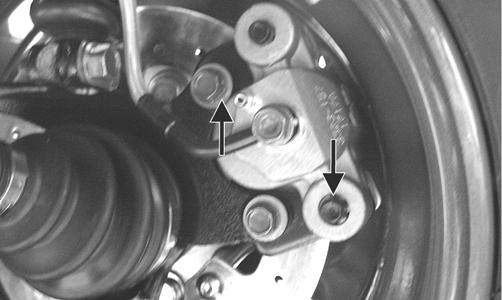
Brake Hose Caliper 20 27
Brake Hose
Master Cylinder 20 27 Brake Hose Brake Cylinder 20 27 Master Cylinder (Rear) Frame 8 11 Master Cylinder Clamp (Front) Master Cylinder 5.5 8 Hydraulic Caliper**** Knuckle 20 27 Brake Pedal Frame 20 27 ELECTRICAL COMPONENTS
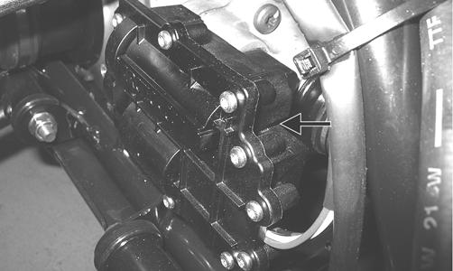
Coil Frame 12 16 Starter Motor Positive Cable Starter Motor 8 11 Stator Coil** Housing 8 11 CHASSIS COMPONENTS
Footrest Frame
20 27 Bumper Frame (8 mm) 20 27 STEERING COMPONENTS Steering Post Bearing Housing Frame 20 27 Handlebar Cap Steering Post 20 27 Lower Steering Post Bearing Cap Steering Post 40 54 Screw Tie Rod End Steering Post Arm 30 41 ENGINE/TRANSMISSION
Clutch Shoe** Crankshaft 147 199 Clutch Cover/Housing Assembly Crankcase 8 11 Left-Side Cover Crankcase 8 11 Crankcase Half (6 mm) Crankcase Half 10 13.5 Crankcase Half (8 mm) Crankcase Half 21 28 Cylinder Nut Crankcase Half 8 11 Cylinder Head (Cap Screw) Crankcase 28 38 Cylinder Head Nut Cylinder 20 27 Cylinder Head Cover Cylinder Head 8 11 Oil Pump Drive Gear** Crankshaft 63 86 Driven Pulley Nut** Driveshaft 147 199 Ground Cable Engine 8 11 Magneto Rotor Flange Nut Crankshaft 107 146 One-Way Clutch** Flywheel 26 35 Cam Sprocket** Camshaft 11 15 V-Belt Cover Clutch Cover 8 11 Valve Adjuster Jam Nut Valve Adjuster 7 9.5 Starter Motor Crankcase 8 11 Oil Fitting Engine 8 11 Oil Pump** Crankcase 8 11 Movable Drive Face Nut** Clutch Shaft 147 199 Output Shaft Flange Nut Output Shaft 59 80 Cam Chain Tensioner Guide Cylinder 11 15 Valve Cover Cylinder 8 11 Tappet Cover Valve Cover 8 11 Cam Chain Tensioner Cylinder 10 13.5 Magneto Cover Crankcase 8 11 Rear Driveline Output Drive Flange 20 27 Water Pump Cover/Housing Magneto Cover 8 11 Water Pump Drive Gear Crankshaft 28 38 Intake Clamp Intake Boot 30 in.-lb 3.4 Part Part Bolted To
Torque ft-lb N-m
A-Arm Knuckle Frame Ball Joint 35 47 35 47
Shock Absorber Frame 35 47
Shock Absorber Knuckle Upper A-Arm 35 47 A-Arm 35 47
SUSPENSION COMPONENTS (Rear) Shock Absorber (Upper) Frame 35 47 Shock Absorber (Lower) Lower A-Arm 35 47 A-Arm Frame 35 47 Knuckle A-Arm 35 47 DRIVE TRAIN COMPONENTS Engine Mounting Through-Bolt Frame 38 52 Front Differential Frame/Differential 38 52 Bracket Output Flange Rear Flange Output 20 27 Joint Input Shaft Housing Differential Housing 18 25 Pinion Housing Gear Case Housing 18 25 Differential Housing Cover*** Differential Housing 18 25 Drive Bevel Gear Nut** Shaft 59 80 Driven Bevel Gear Nut** Driven Shaft 59 80 Thrust Button** Gear Case Cover 8 11 Hub Nut Shaft/Axle (max) 200 272 Oil Drain Plug Front Differential/ 45 in.-lb 5 Rear Drive Oil Fill Plug Front Differential/ 16 22 Rear Drive Oil Drain Plug Engine 20 27 Rear Drive Input Shaft Housing Differential Housing 23 31 Lock Collar Differential Housing 125 169 Wheel Hub 80 108 Rear Drive Gear Case Frame 38 52 Engine Output Flange Rear Gear Case 20 27 Input Flange * w/Blue Loctite #243 ** w/Red Loctite #271 *** w/Green Loctite #609 ****w/“Patch-Lock”
Torque Conversions (ft-lb/N-m)
Gasoline - Oil - Lubricant
ft-lb N-m ft-lb N-m ft-lb N-m ft-lb N-m 1 1.4 26 35.4 51 69.4 76 103.4 2 2.7 27 36.7 52 70.7 77 104.7 3 4.1 28 38.1 53 72.1 78 106.1 4 5.4 29 39.4 54 73.4 79 107.4 5 6.8 30 40.8 55 74.8 80 108.8 6 8.2 31 42.2 56 76.2 81 110.2 7 9.5 32 43.5 57 77.5 82 111.5 8 10.9 33 44.9 58 78.9 83 112.9 9 12.2 34 46.2 59 80.2 84 114.2 10 13.6 35 47.6 60 81.6 85 115.6 11 15 36 49 61 83 86 117 12 16.3 37 50.3 62 84.3 87 118.3 13 17.7 38 51.7 63 85.7 88 119.7 14 19 39 53 64 87 89 121 15 20.4 40 54.4 65 88.4 90 122.4 16 21.8 41 55.8 66 89.8 91 123.8 17 23.1 42 57.1 67 91.1 92 125.1 18 24.5 43 58.5 68 92.5 93 126.5 19 25.8 44 59.8 69 93.8 94 127.8 20 27.2 45 61.2 70 95.2 95 129.2 21 28.6 46 62.6 71 96.6 96 130.6 22 29.9 47 63.9 72 97.9 97 131.9 23 31.3 48 65.3 73 99.3 98 133.3 24 32.6 49 66.6 74 100.6 99 134.6 25 34 50 68 75 102 100 136
RECOMMENDED GASOLINE The recommended gasoline to use is 87 minimum octane regular unleaded. In many areas, oxygenates (either ethanol or MTBE) are added to the gasoline. Oxygenated gasolines containing up to 10% ethanol, 5% methane, or 5% MTBE are acceptable gasolines. When using ethanol blended gasoline, it is not necessary to add a gasoline antifreeze since ethanol will prevent the accumulation of moisture in the fuel system.
CAUTION
Do not use white gas. Only Arctic Cat approved gasoline additives should be used. CAUTION
Any oil used in place of the recommended oil could cause serious engine damage. Do not use oils which contain graphite or molybdenum additives. These oils can adversely affect clutch operation. Also, not recommended are racing, vegetable, non-detergent, and castor-based oils.
The recommended oil to use is Arctic Cat ACX All Weather synthetic engine oil, which has been specifically formulated for use in this Arctic Cat engine. Although Arctic Cat ACX All Weather synthetic engine oil is the only oil recommended for use in this engine, use of any API certified SM 0W-40 oil is acceptable.
OILCHARTJ
RECOMMENDED FRONT DIFFERENTIAL/REAR DRIVE LUBRICANT The recommended lubricant is Arctic Cat Gear Lube or an equivalent gear lube which is SAE approved 80W-90 hypoid. This lubricant meets all of the lubrication requirements of the Arctic Cat ATV front differentials and rear drives.
CAUTION
Any lubricant used in place of the recommended lubricant could cause serious front differential/rear drive damage. FILLING GAS TANK ! WARNING
Always fill the gas tank in a well-ventilated area. Never add fuel to the ATV gas tank near any open flames or with the engine running. DO NOT SMOKE while filling the gas tank. Since gasoline expands as its temperature rises, the gas tank must be filled to its rated capacity only. Expansion room must be maintained in the tank particularly if the tank is filled with cold gasoline and then moved to a warm area.
! WARNING
ATV0049B
Do not overflow gasoline when filling the gas tank. A fire hazard could materialize. Always allow the engine to cool before filling the gas tank. Tighten the gas tank cap securely after filling the tank. ! WARNING
Do not over-fill the gas tank.
Genuine Parts
When replacement of parts is necessary, use only genuine Arctic Cat ATV parts. They are precision-made to ensure high quality and correct fit. Refer to the Illustrated Parts Manual for the correct part number, quantity, and description.
Preparation For Storage
CAUTION
Prior to storing the ATV, it must be properly serviced to prevent rusting and component deterioration.
1. Clean the seat cushion (cover and base) with a damp cloth and allow it to dry. 2. Clean the ATV thoroughly by washing dirt, oil, grass, and other foreign matter from the entire ATV.
Allow the ATV to dry thoroughly. DO NOT get water into any part of the engine or air intake. 3. Either drain the gas tank or add Fuel Stabilizer to the gas in the gas tank. Remove the air filter housing cover and air filter. Start the engine and allow it to idle; then using Arctic Cat Engine Storage Preserver, rapidly inject the preserver into the air filter opening for a period of 10 to 20 seconds. Stop the engine.
Install the air filter and housing cover.
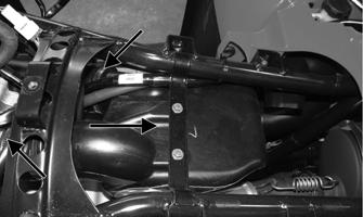
4. Plug the exhaust outlet on the muffler with a clean cloth. 5. Apply light oil to the upper steering post bushing and plungers of the shock absorbers. 6. Tighten all nuts, bolts, cap screws, and screws. Make sure rivets holding components together are tight.
Replace all loose rivets. Care must be taken that all calibrated nuts, cap screws, and bolts are tightened to specifications. 7. Fill the cooling system to the bottom of the stand pipe in the radiator neck with properly mixed coolant. 8. Disconnect the battery cables; then remove the battery, clean the battery posts and cables, and store in a clean, dry area. 9. Store the ATV indoors in a level position.
CAUTION
If the interior of the air filter housing is dirty, clean the area before starting the engine. CAUTION
Avoid storing outside in direct sunlight and avoid using a plastic cover as moisture will collect on the ATV causing rusting.
Preparation After Storage
Taking the ATV out of storage and correctly preparing it will assure many miles and hours of trouble-free riding. 1. Clean the ATV thoroughly. 2. Clean the engine. Remove the cloth from the muffler. 3. Check all control cables for signs of wear or fraying.
Replace if necessary. 4. Change the engine/transmission oil and filter. 5. Check the coolant level and add properly mixed coolant as necessary. 6. Charge the battery; then install. Connect the battery cables.
7. Check the entire brake systems (fluid level, pads, etc.), all controls, lights, and headlight aim; adjust or replace as necessary. 8. Tighten all nuts, bolts, cap screws, and screws making sure all calibrated nuts, cap screws, and bolts are tightened to specifications. 9. Check tire pressure. Inflate to recommended pressure as necessary. 10. Make sure the steering moves freely and does not bind. 11. Check the spark plug. Clean or replace as necessary.
CAUTION
The ignition switch must be in the OFF position prior to installing the battery or damage may occur to the ignition system.
CAUTION
Connect the positive battery cable first; then the negative.